|
|
Expert
Posts: 1208
 
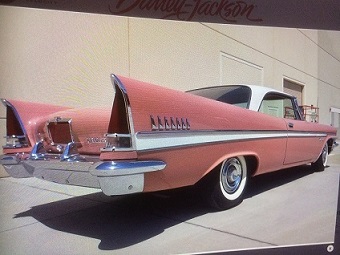
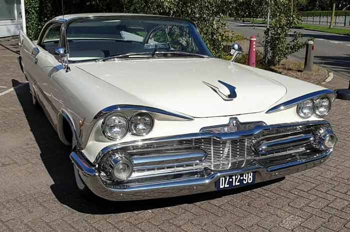
Location: SWITZERLAND | I have started modeling my '59 Dodge. I have the technology, the know-how, some time for do this, and last but not least - the authentic car in my home. In Internet I found some other models, some of them very nice, but most from drawings or pictures, therefore not exact and looking artificially. I would like to do it perfect, as my car, with the correct dimensions, and in real-view technology. This designs could as well be used for direct tooling and professional reproduction. This will take some time, and one day hopefully, the '59 Dodge will stay here like an Original! The first problem is to get the correct dimensions, curves and shapes. The next problem is to put these original "hand-designed" data geometrically in the system. What remains is puzzle. I will start with the more complex chrome parts, emblems, and then go on to the body. All the pictures shown here will be unexpectionally 3D-Cad Designs. May-be there are Members with the similar potential in supporting this objective, using SolidWorks, or does some parts have already been designed?
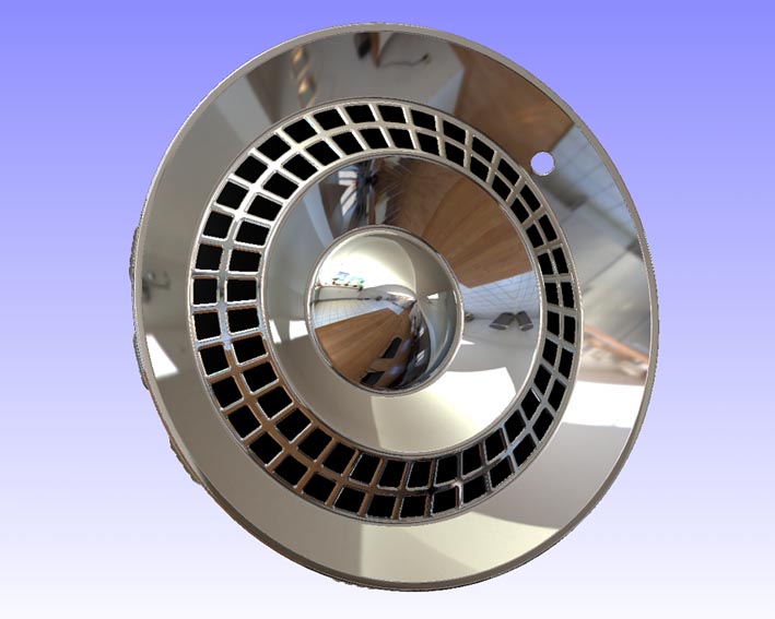 (01 CAD 1959 HubCap Front1.jpg) (01 CAD 1959 HubCap Front1.jpg)
 (02 CAD 1959 HubCap Front2.jpg) (02 CAD 1959 HubCap Front2.jpg)
 (03 CAD 1959 HubCap Rear1.jpg) (03 CAD 1959 HubCap Rear1.jpg)
 (04 CAD 1959 HubCap Rear2.jpg) (04 CAD 1959 HubCap Rear2.jpg)
Attachments
----------------
 01 CAD 1959 HubCap Front1.jpg (70KB - 536 downloads) 01 CAD 1959 HubCap Front1.jpg (70KB - 536 downloads)
02 CAD 1959 HubCap Front2.jpg (68KB - 531 downloads)
03 CAD 1959 HubCap Rear1.jpg (54KB - 514 downloads)
04 CAD 1959 HubCap Rear2.jpg (54KB - 519 downloads)
|
|
| |
|
Expert 5K+
Posts: 8443
  
Location: Perth Australia | I wish you the best of luck.
That would really be hard to do. Be good if you could use a laser or microwave or something like that (like a surveyeyer uses) to sort of slice the car up didgitally.
Mick |
|
| |
|

Board Moderator & Exner Expert 10K+
Posts: 13049
Location: Southern Sweden - Sturkö island | This, is hard-core dedication!! Amazing Serge! |
|
| |
|
Expert
Posts: 3575

Location: Netherlands | sermey - 2010-12-16 5:24 PM
All the pictures shown here will be unexpectionally 3D-Cad Designs.
Wow, I didn't expect that, but I'm sure they will be of exceptional quality!  
How many hours have you spent on the hubcap already? |
|
| |
|
Location: Parts Unknown | This kind of thing will make reproduction of parts easy.  |
|
| |
|
Expert 5K+
Posts: 8443
Location: Perth Australia | Sermey
How does it do it? The first one has reflections in it. I thought it was all measurement based or something. I have to admit to knowing nothing about CAD
Mick |
|
| |
|
Elite Veteran
Posts: 774
Location: Atlanta GA USA | And someday they'll make a machine to produce a car from the CAD data. One part down, a few more to go. Looking good! |
|
| |
|
Elite Veteran
Posts: 988
Location: Kansas City, Kansas | Very cool. When complete, please share your cad file with us. I would love for my office to add a '59 Dodge to our architectural renderings. (might help distract the viewer from any bad architecture!) |
|
| |
|
Expert
Posts: 1208
Location: SWITZERLAND | ttotired: Be good if you could use a laser or microwave . . .
Just for have it in 3D could work for some parts (not for a HubCap as shown), similar to a scanned photo. Have a look at parts being reproduced with Originals as Master, most of them visibla as Copy and not as not as Original.
To copy, as I do here, is not creative at all. But but the way, the tool and the stunning results are a challenge for the brain.and as well an enjoyment.
ttotired: The first one has reflections in it . . .
Scenes and material can be assigned to the model. Here I used "warm kitchen" for remove the technical aspect, and "polished chrome" for an Original look. The rear side is matt with no reflections, as the Original HubCap.(material could be stone, rubber, wood, or whatever).
1956DeS: And someday they'll make a machine to produce a car from the CAD data.
I think may-be .. in 50 years? But in reduced size as did Cadi with one of there cars, and with other Engine/Suspension and Electronics. But overall looking exact same! And these files can be used for direct tooling (without dimensions, or direct sampling with Stereo-Lithography)
slimwhitman: . . . please share your cad file with us. . .
With eDrawing (free download), the parts can be viewed. rotated, zoomed and as well automatic displayed in various views as for show.
Wizard: Thank you for the encouragement!- SERGE -
Edited by sermey 2010-12-21 12:26 PM
|
|
| |
|
Expert
Posts: 1208
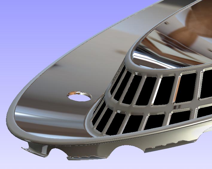
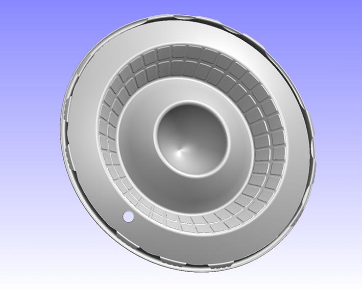
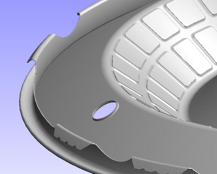
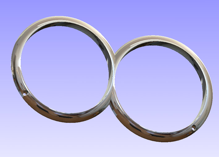
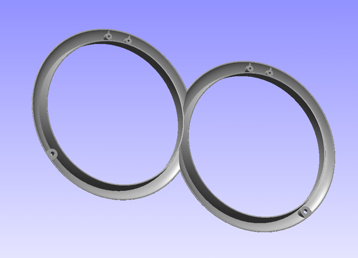
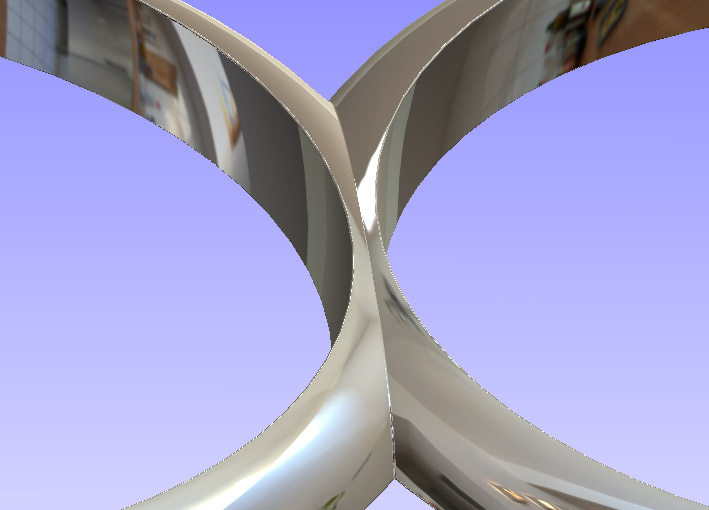
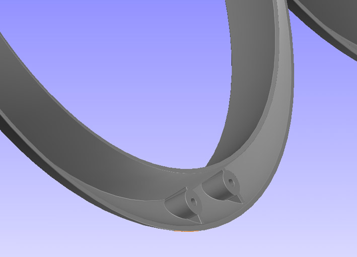
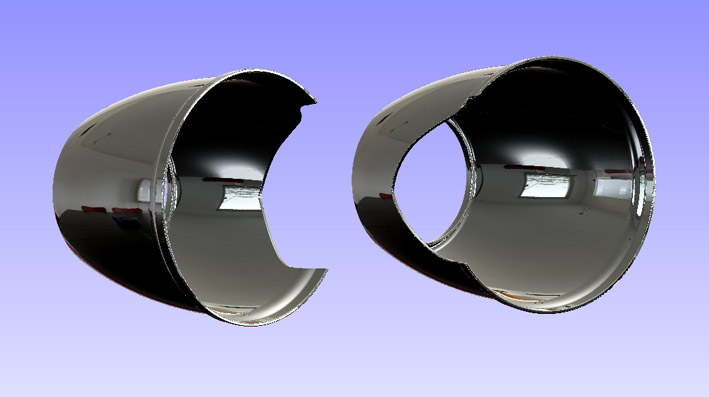
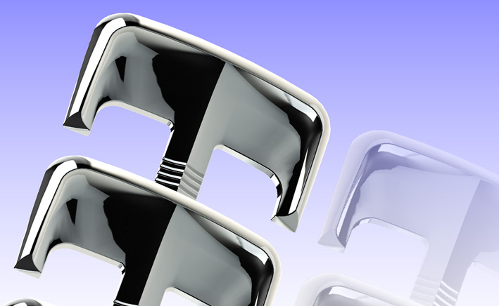
Location: SWITZERLAND | Here is just one HeadLamp Ring. The other can simply be mirrored as many other Car Parts to come.
Who is owner of a 1959 Dodge can easy compare this design with the Original. There are minor differences from one part to the other, even the rings are not exactly round. Here I did it "correct"! (All pictures shown are PrintScreens and reduced in Size)
Edited by sermey 2010-12-21 1:11 PM
 (01 CAD 1959 HeadLamp Ring Front.jpg) (01 CAD 1959 HeadLamp Ring Front.jpg)
 (02 CAD 1959 HeadLamp Ring Rear.jpg) (02 CAD 1959 HeadLamp Ring Rear.jpg)
 (03 CAD 1959 HeadLamp Ring Center.jpg) (03 CAD 1959 HeadLamp Ring Center.jpg)
 (04 CAD 1959 HeadLamp Ring Mounts.jpg) (04 CAD 1959 HeadLamp Ring Mounts.jpg)
Attachments
----------------
01 CAD 1959 HeadLamp Ring Front.jpg (66KB - 585 downloads)
02 CAD 1959 HeadLamp Ring Rear.jpg (56KB - 606 downloads)
03 CAD 1959 HeadLamp Ring Center.jpg (61KB - 599 downloads)
04 CAD 1959 HeadLamp Ring Mounts.jpg (46KB - 590 downloads)
|
|
| |
|
Expert
Posts: 3575
Location: Netherlands | As an owner now of a '59 Dodge in parts I will be comparing your work against the real deal...
Here's my 'rendering' of parts...

|
|
| |
|
Expert 5K+
Posts: 8443
Location: Perth Australia | Sermey
I downloaded eDraw so now I will play with it to see how it works.
Hats off to you!!!
Mick |
|
| |
|
Expert
Posts: 1208
Location: SWITZERLAND | ttotired - 2010-12-22 12:11 AM Sermey I downloaded eDraw so now I will play with it to see how it works. Hats off to you!!! Mick I put you an eDrawing File with the Coil Support as shown in "My Electronic Ignition Conversion". The downloaded eDrawing doesn't support RealView, thus no reflective Chrome . For this you will need the professional version (not free). Anyway, everyone here, I recommend, can check this tool to get a feeling what is real 3D-CAD, and look how it works - amazing to play with. - SERGE -
Edited by sermey 2010-12-22 5:00 AM
Attachments
----------------
2008-10-20 CoilSupport.EPRT (186KB - 587 downloads)
|
|
| |
|
Expert
Posts: 1208
Location: SWITZERLAND | BigBlockMopar - 2010-12-21 8:14 PM As an owner now of a '59 Dodge in parts I will be comparing your work against the real deal... Here's my 'rendering' of parts...
Impressive all these nice rechromed parts. You will enjoy mounting them as I did some years ago. Now I will enjoy as well when assembling my CAD-Parts. The difference, I will keep clean hands and drink my coffee simultaneously. - SERGE - :laugh:
Edited by sermey 2010-12-22 11:48 AM
|
|
| |
|
Expert 5K+
Posts: 8443
Location: Perth Australia | sermey
Thats cool, love it. I should try to learn it one day, could help me with my work
Thanks
Mick |
|
| |
|
Expert
Posts: 1208
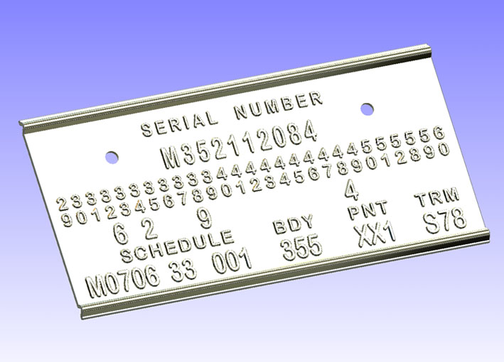
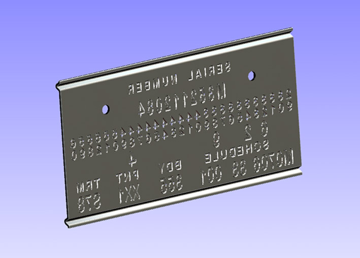
Location: SWITZERLAND | This is the TAG-Plate of my 1959 DODGE Convertible, as already shown in another thread. But this one is revised:
The character of the letters and there position is adapted to the Original. Then the plate has the correct border, and what was very critical to realize, on the rear of the plate, the letters are "stamped" as in production.
Edited by sermey 2010-12-22 11:46 AM
 (01 CAD 1959 TAG-Plate Front.jpg) (01 CAD 1959 TAG-Plate Front.jpg)
 (02 CAD 1959 TAG-Plate Rear.jpg) (02 CAD 1959 TAG-Plate Rear.jpg)
Attachments
----------------
01 CAD 1959 TAG-Plate Front.jpg (83KB - 602 downloads)
02 CAD 1959 TAG-Plate Rear.jpg (72KB - 592 downloads)
|
|
| |
|
Expert
Posts: 2289
Location: Eastern Iowa | Man, that's in really great shape for being 91 years old!!
Dave S. |
|
| |
|

Location: The Mile High City | Whoa! Absolutely fantastic! When you are finished with the 3D-CAD drawings of the '59 Dodge, can you make a 3D-CAD model of Amanda Peet? |
|
| |
|
Expert
Posts: 1208
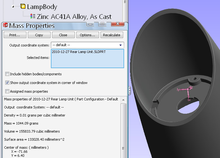
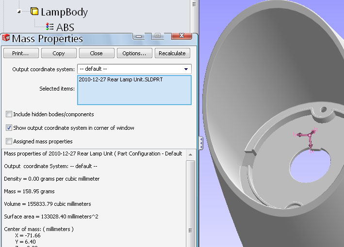
Location: SWITZERLAND | Going on modeling some other parts, I weighted the Rear Lamp Body, well-known by every owner of a 1959 Dogde. I measured exactly 1000 grams, say 1 kg. BigBlockMopar will kindly check and confirm this value. On the CAD Rear Lamp Body I have assigned the Material "Zinc, As Cast" and got a weight of 1044.09 grams. Then I assigned as well plastic "ABS", as used for rechromed plastics, and got a weight of 158.95 grams. Means, alone these 4 Bodies, reproduced in Rechromed Plastics, would reduce 3.36 kg of the cars weight, the volume and the surface area of this Body remaining the same. Impressive numbers!
Edited by sermey 2010-12-26 10:58 AM
 (01 CAD 1959 RearLamp Weight Zinc.jpg) (01 CAD 1959 RearLamp Weight Zinc.jpg)
 (02 CAD 1959 RearLamp Weight ABS.jpg) (02 CAD 1959 RearLamp Weight ABS.jpg)
Attachments
----------------
01 CAD 1959 RearLamp Weight Zinc.jpg (99KB - 581 downloads)
02 CAD 1959 RearLamp Weight ABS.jpg (89KB - 590 downloads)
|
|
| |
|
Expert
Posts: 3575
Location: Netherlands | I don't have a scale in my garage to measure that but maybe I could make a balance with a liter of water to see how close it is to a kilo. Don't you love how logical the metric is guys... 
|
|
| |
|
Expert
Posts: 1208
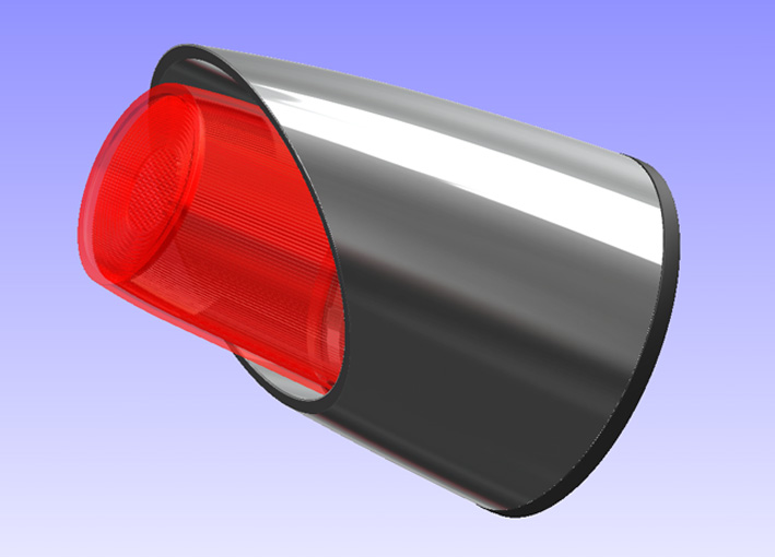
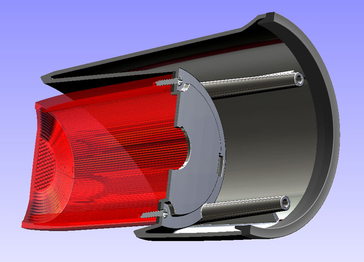
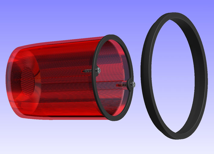
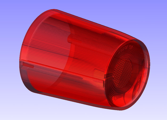
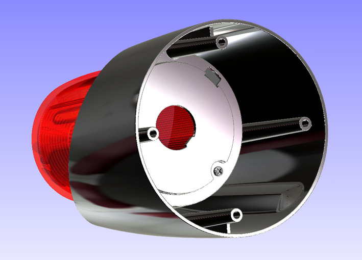
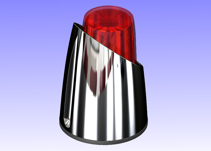
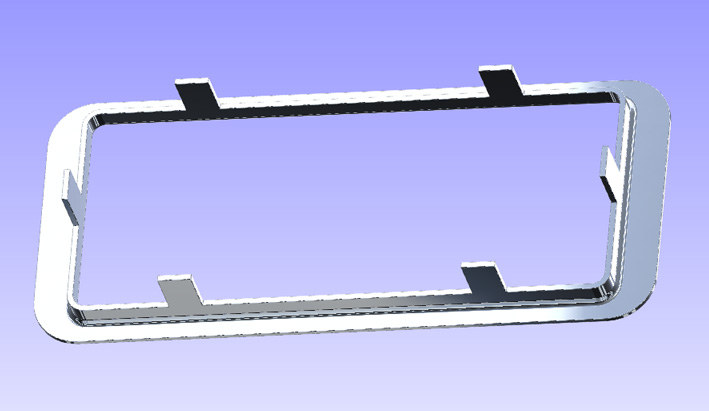
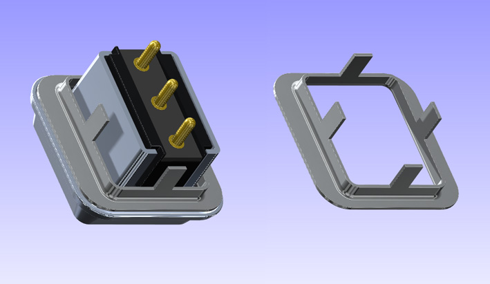
Location: SWITZERLAND | This tricky "game" I expected to be easier - finally I got it. The Rear Lamp Unit: Body, Lens, Seal, Ring, Screws. All modeled in a Single Multipart File.
The three asymmetrical mounting studs I replaced with four symmetrical ones, for a mounting in any position of the car: right side top, right side bottom, and on the left side correspondingly. I also removed the rear injection points around the Lamp Socket.
One more perfect "restored" Unit on the way to the virtual 1959 DODGE. - SERGE -
I added eDrawing-Files: PanHead Screw, 1959 Rear Lamp Seal, 1959 Rear Lamp Ring, as illustrated here. The Rear Lamp Ring can be seen on the car in the thread "Make-up your Car".
Edited by sermey 2011-01-02 5:42 PM
 (01 CAD 1959 Rear Lamp Unit.jpg) (01 CAD 1959 Rear Lamp Unit.jpg)
 (02 CAD 1959 Section View.jpg) (02 CAD 1959 Section View.jpg)
 (03 CAD 1959 Body Removed.jpg) (03 CAD 1959 Body Removed.jpg)
 (04 CAD 1959 Lens DODGE Script.jpg) (04 CAD 1959 Lens DODGE Script.jpg)
 (05 CAD 1959 Lamp Rear View.jpg) (05 CAD 1959 Lamp Rear View.jpg)
 (06 CAD 1959 Rear Lamp Up View.jpg) (06 CAD 1959 Rear Lamp Up View.jpg)
Attachments
----------------
01 CAD 1959 Rear Lamp Unit.jpg (73KB - 602 downloads)
02 CAD 1959 Section View.jpg (81KB - 590 downloads)
03 CAD 1959 Body Removed.jpg (70KB - 577 downloads)
04 CAD 1959 Lens DODGE Script.jpg (97KB - 594 downloads)
05 CAD 1959 Lamp Rear View.jpg (74KB - 582 downloads)
06 CAD 1959 Rear Lamp Up View.jpg (63KB - 595 downloads)
Short Screw PanHead D3.5mm.EPRT (280KB - 573 downloads)
1959 Rear Lamp Seal.EPRT (72KB - 582 downloads)
1959 Rear Lamp Ring.EPRT (107KB - 616 downloads)
|
|
| |
|
Expert
Posts: 3575
Location: Netherlands | Looks very nice!
I see one error though...!
The thread on the screw in the 3rd pic is lefthand thread! ...
|
|
| |
|
Board Moderator & Exner Expert 10K+
Posts: 13049
Location: Southern Sweden - Sturkö island | Absolutely fantastic - it's so beautiful! |
|
| |
|
Expert
Posts: 1208
Location: SWITZERLAND | BigBlockMopar - 2011-01-02 11:25 PM Looks very nice! I see one error though...! The thread on the screw in the 3rd pic is lefthand thread! ... Congrat Hermann, you are very observant. In fact, because I did this set as a MultiPart in a single file, I just "mirrored" the screw and got therefore a second one with lefthand thread. Now I will "array" the screw and both will have righthand thread - thanks.
Edited by sermey 2011-01-03 2:47 AM
|
|
| |
|
Expert
Posts: 1208
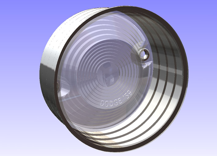
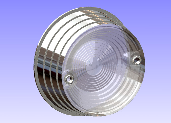
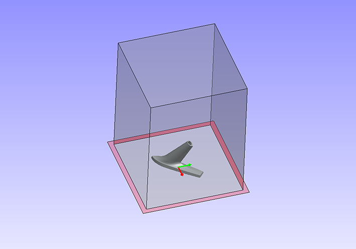
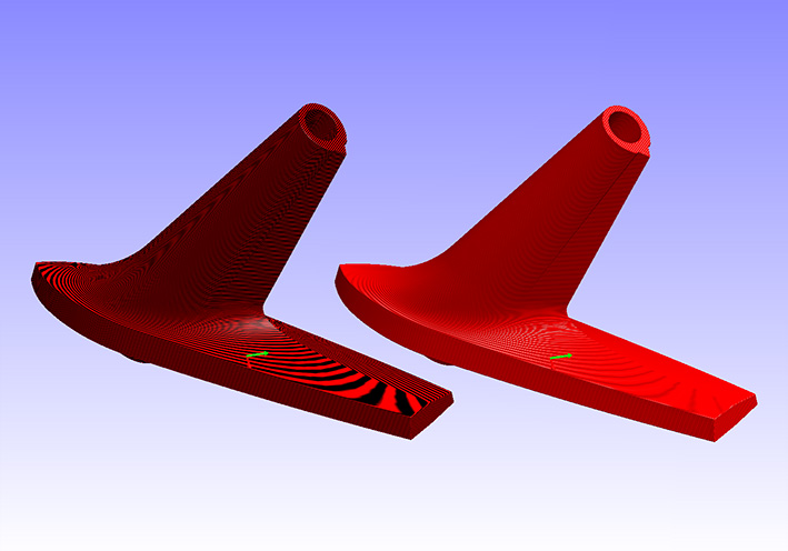
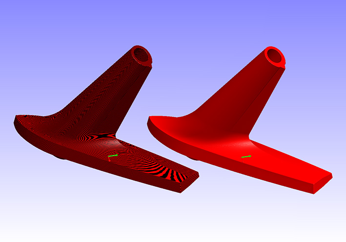
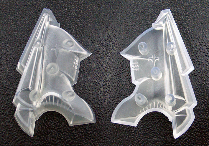
Location: SWITZERLAND | This Parking Lens may be one of the easiest parts to model: just sketch the profile and revolve. Often broken, they are hard to find NOS and thus quite expensive. The reproductions, available on the market, are silver painted on the outern surface, instead chrome plated as original. Here you see it correctly.
On my DODGE I use another lense, will be shown later on in the assembly. For security reasons, in Switzerland this light should be visible at a side angle of 150deg.
 (01 CAD 1959 Parking Lens Front View .jpg) (01 CAD 1959 Parking Lens Front View .jpg)
 (02 CAD 1959 Parking Lens Rear View.jpg) (02 CAD 1959 Parking Lens Rear View.jpg)
 (03 CAD 1959 Parking Lens Section View.jpg) (03 CAD 1959 Parking Lens Section View.jpg)
 (04 CAD 1959 Parking Lens Intransparent.jpg) (04 CAD 1959 Parking Lens Intransparent.jpg)
Attachments
----------------
01 CAD 1959 Parking Lens Front View .jpg (83KB - 611 downloads)
02 CAD 1959 Parking Lens Rear View.jpg (89KB - 590 downloads)
03 CAD 1959 Parking Lens Section View.jpg (80KB - 569 downloads)
04 CAD 1959 Parking Lens Intransparent.jpg (51KB - 628 downloads)
|
|
| |
|
Expert
Posts: 1208
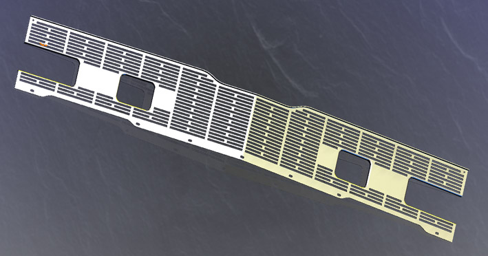
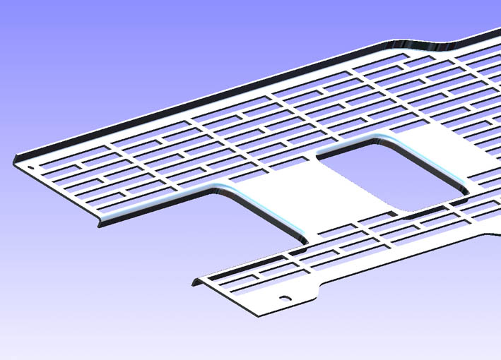
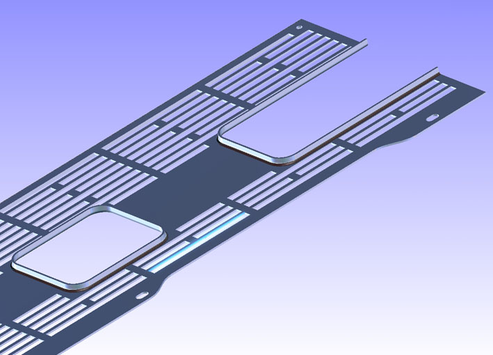
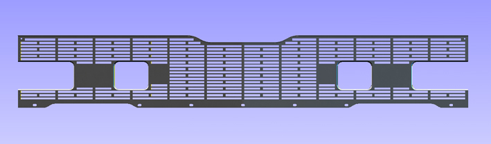
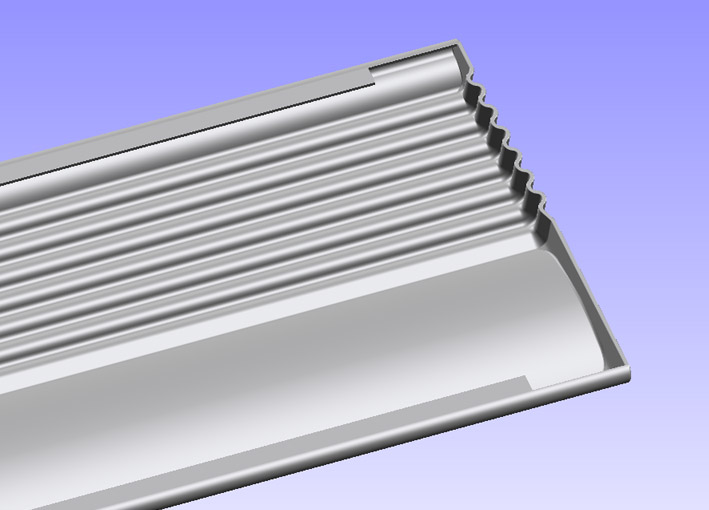
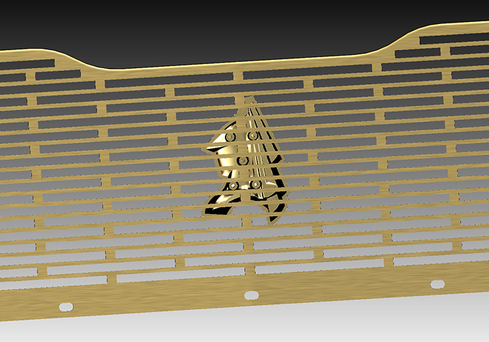
Location: SWITZERLAND | This is the 1959 Front Grill, in brushed Aluminium. Here I omitted the upper fixing tabs and the stabilizers on the rear for a nicer aspect.
The Front is center-angeled by 5 degree, not remarkable on the car. The Chrome Bars left and right hand, here not shown, are parallel and thus have as well a 5deg angle each other.
 (01 CAD 1959 Grill Perspective View.jpg) (01 CAD 1959 Grill Perspective View.jpg)
 (02 CAD 1959 Grill Left Front End.jpg) (02 CAD 1959 Grill Left Front End.jpg)
 (03 CAD 1959 Grill Left Rear End.jpg) (03 CAD 1959 Grill Left Rear End.jpg)
 (04 CAD 1959 Grill Exact Front View.jpg) (04 CAD 1959 Grill Exact Front View.jpg)
Attachments
----------------
01 CAD 1959 Grill Perspective View.jpg (83KB - 606 downloads)
02 CAD 1959 Grill Left Front End.jpg (86KB - 589 downloads)
03 CAD 1959 Grill Left Rear End.jpg (83KB - 584 downloads)
04 CAD 1959 Grill Exact Front View.jpg (92KB - 600 downloads)
|
|
| |
|
Expert
Posts: 1208
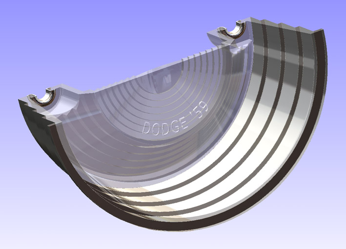
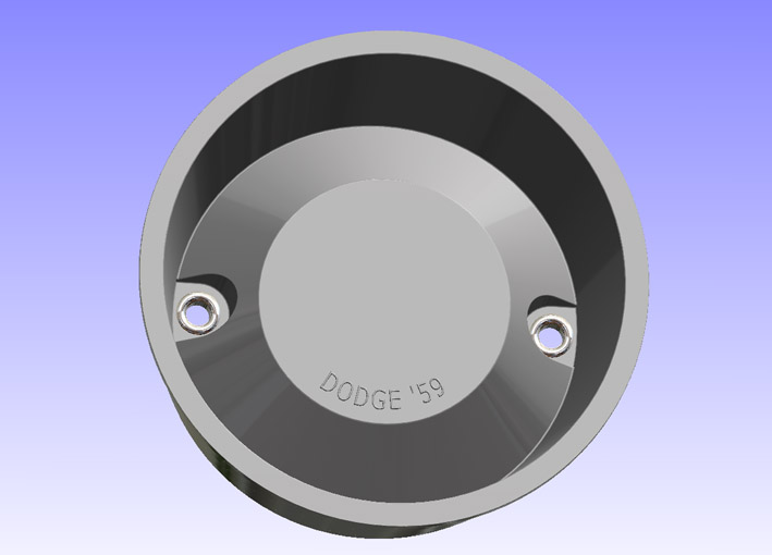
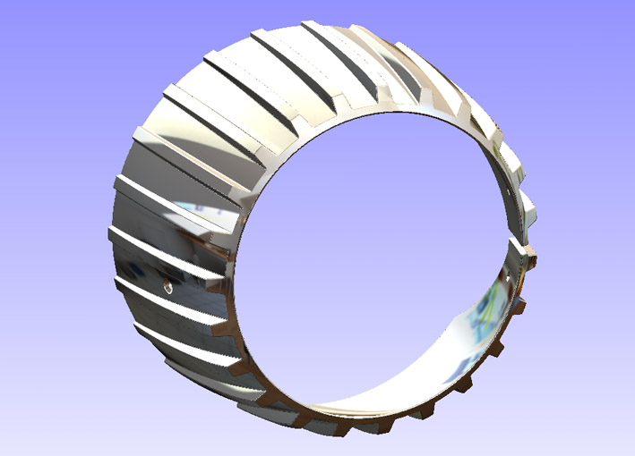
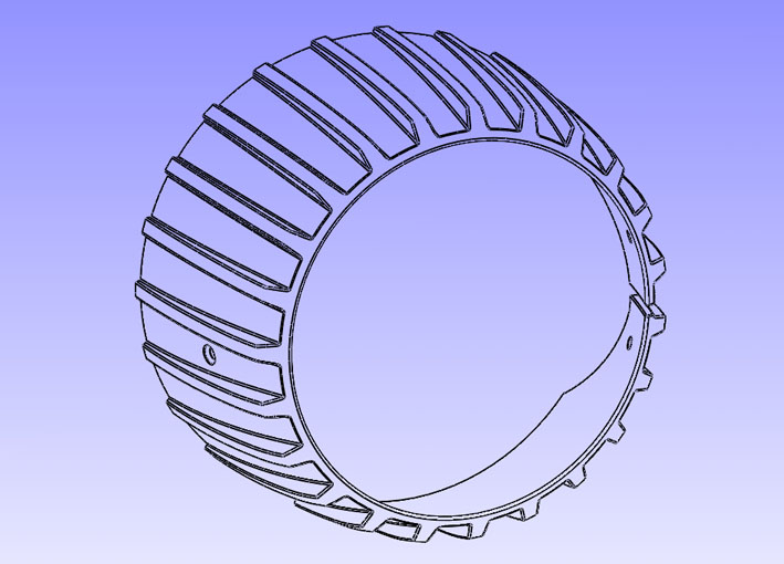
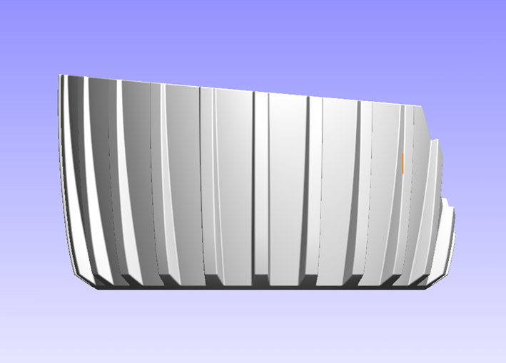
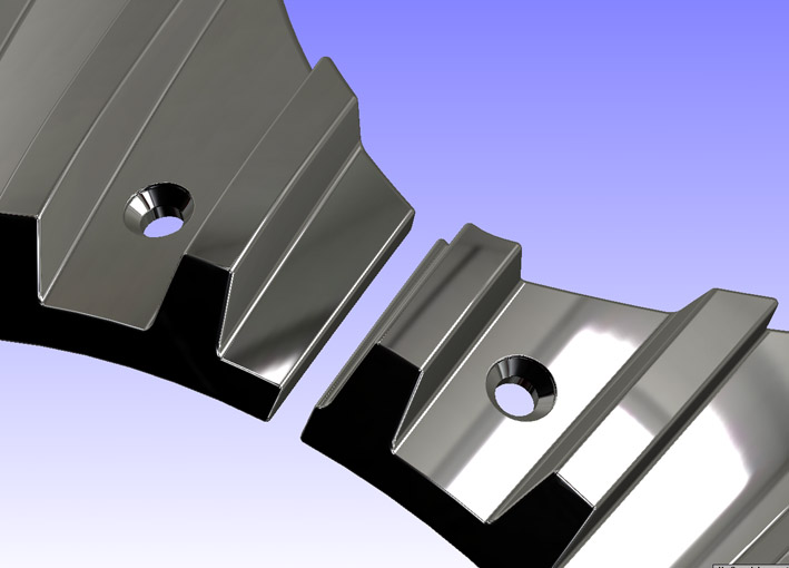
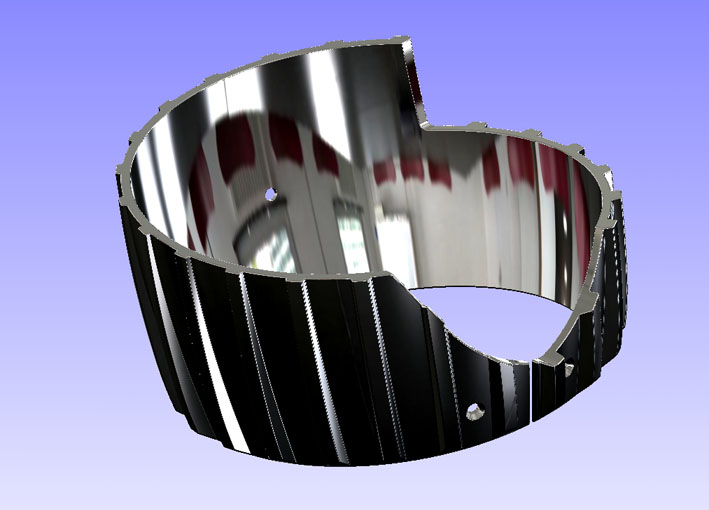
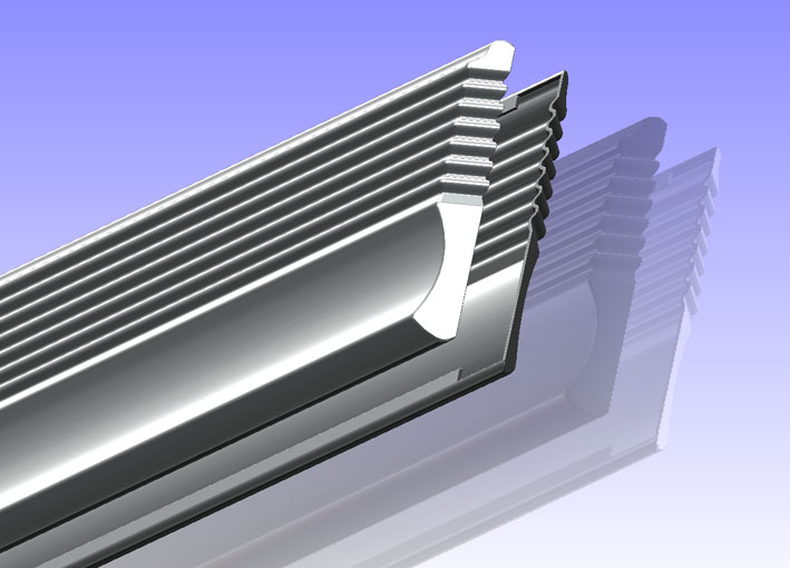
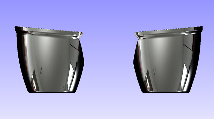
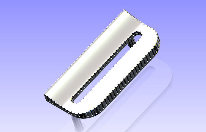
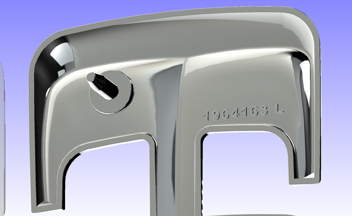
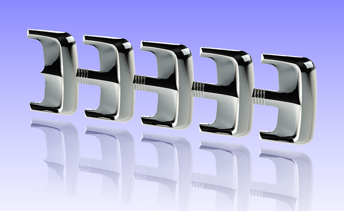
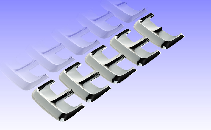
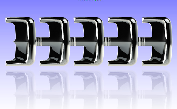
Location: SWITZERLAND | This Collar on the Front Position Lamps was optional only on the '59 Custom Royal. Original there is an upper and a lower half. Here you see the right side Collar. To get the left side one it has to be mirrored.
For an uniform view from side, this Collar here is modeled in one piece and is just cut as original, only on one, the inner side; thus being fixed with only 3 screws. On my car the full round Collar has 23 teeth as on the model - on some Original Brochures I counted less. This is a very rare part to find, here guaranteed pits-free! - SERGE -
Edited by sermey 2011-01-23 2:24 PM
 (01 CAD 1959 Collar Front View.jpg) (01 CAD 1959 Collar Front View.jpg)
 (02 CAD 1959 Collar Front Wire View.jpg) (02 CAD 1959 Collar Front Wire View.jpg)
 (03 CAD 1959 Collar Matte Side View.jpg) (03 CAD 1959 Collar Matte Side View.jpg)
 (04 CAD 1959 Collar View Cut Side.jpg) (04 CAD 1959 Collar View Cut Side.jpg)
 (05 CAD 1959 Collar Rear View.jpg) (05 CAD 1959 Collar Rear View.jpg)
Attachments
----------------
01 CAD 1959 Collar Front View.jpg (74KB - 598 downloads)
02 CAD 1959 Collar Front Wire View.jpg (86KB - 584 downloads)
03 CAD 1959 Collar Matte Side View.jpg (53KB - 591 downloads)
04 CAD 1959 Collar View Cut Side.jpg (69KB - 596 downloads)
05 CAD 1959 Collar Rear View.jpg (69KB - 596 downloads)
|
|
| |
|
Expert
Posts: 3575
Location: Netherlands | Sweet. Nice progress!
|
|
| |
|
Expert
Posts: 1208
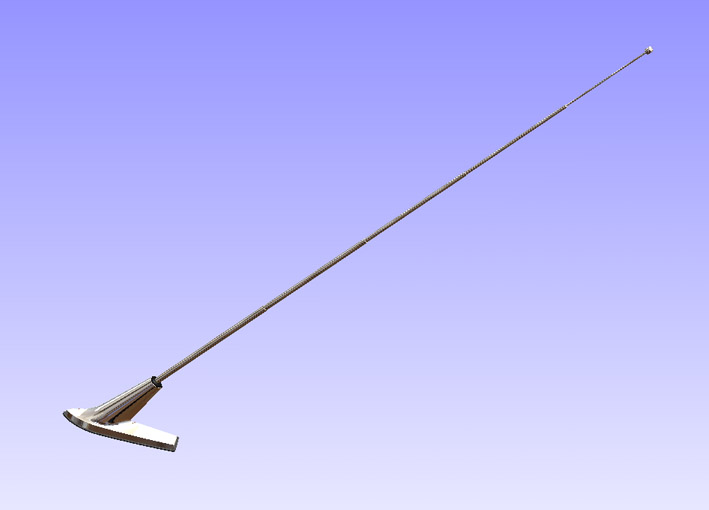
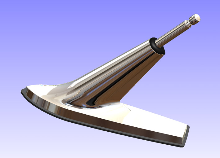
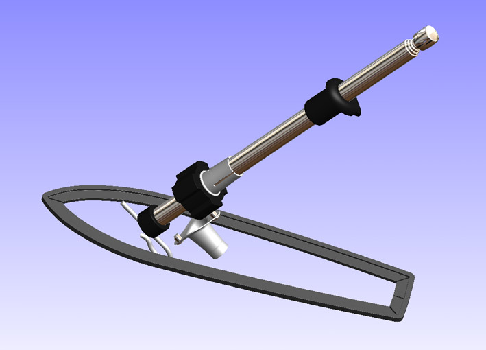
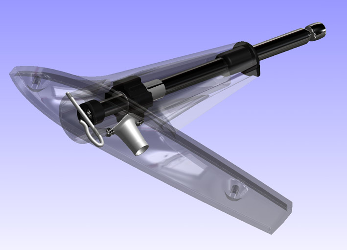
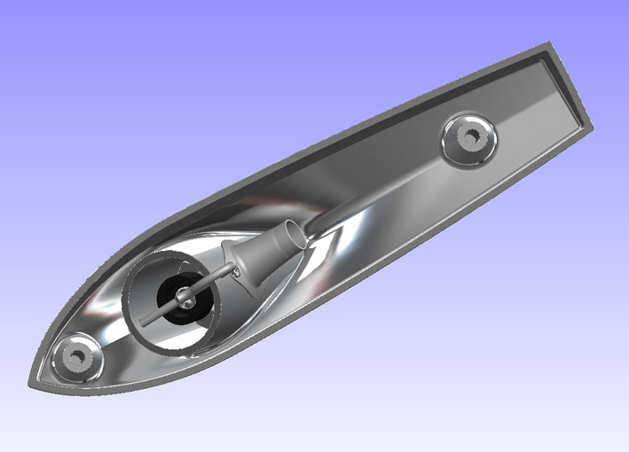
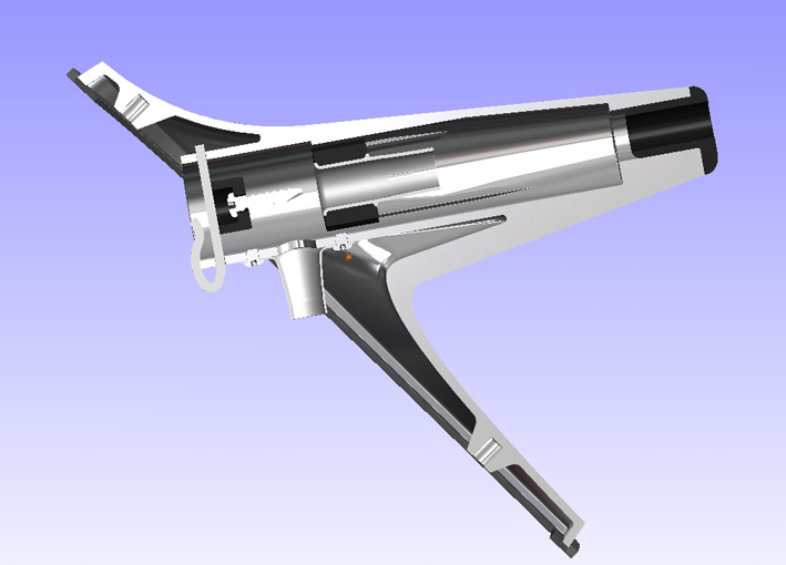
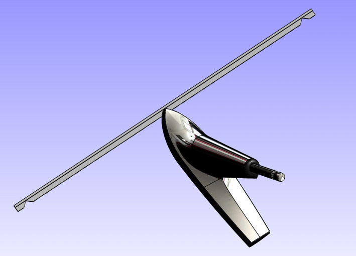
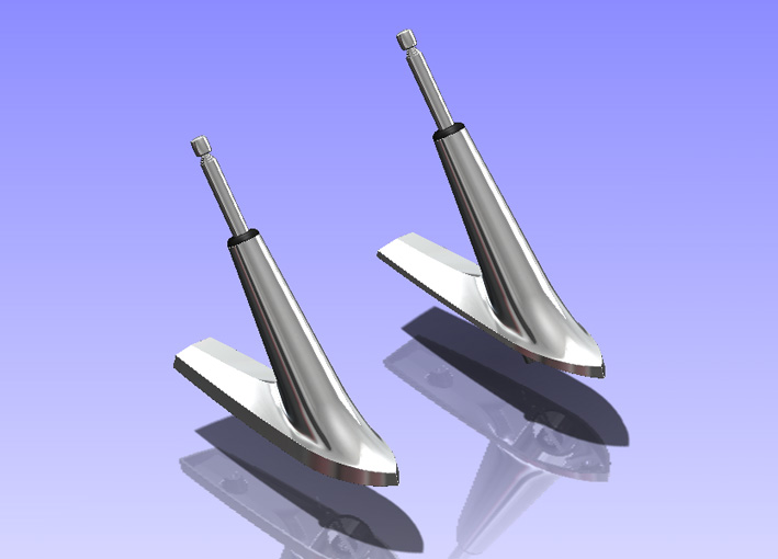
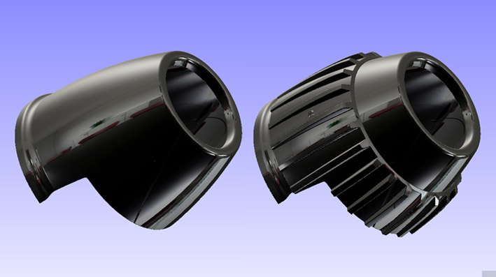
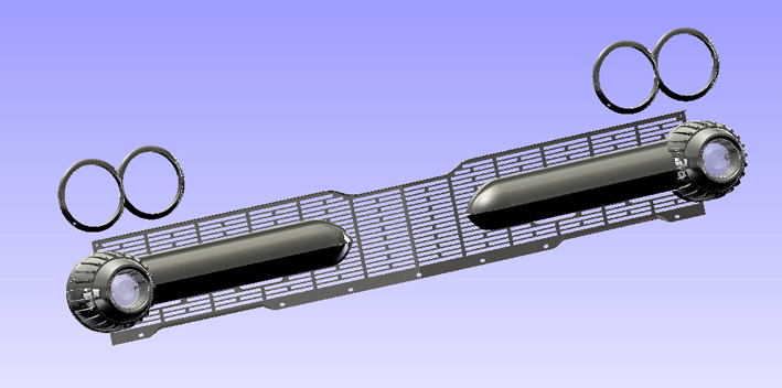
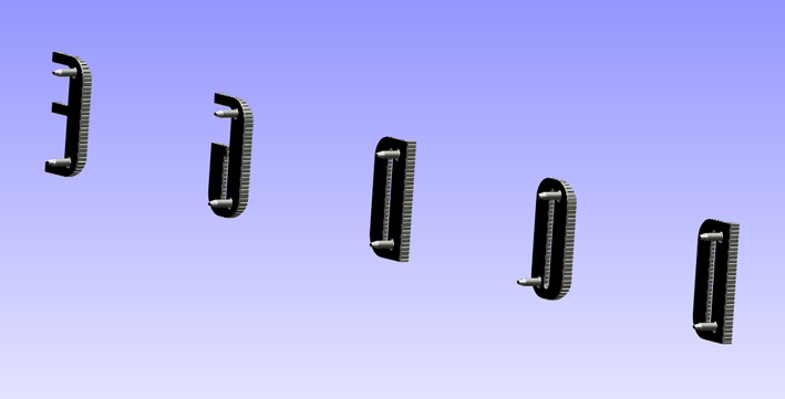
Location: SWITZERLAND | For variation now a part that can be used, as option, on all FWL-Cars: the Dual Rear Antenna, here shown the left side one as set, the right side one mirrored as shown in the last picture
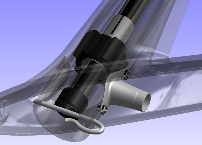
An ingenious concept, combined with a full free surface modeling technology, allowed this complex shape to be implemented quite fast. Thus, I added more details inside the Antenna Body.
The Antenna Bar correspond to my upgraded Automatic Device, I may show it here later on.
On the other hand, here the Antenna Gasket as described in "Make-up your Car!". This Gasket can be mounted without the complicated dissassembling of the the antenna. The 3 cut-out angle have 100deg (+), the partial length are 169.5 + 171 + 25.1 = 365.6mm, the outer circumference has 367.75mm. For a better visibility I did the gaps wider than in reality. A separate file of this gasket is attached for eDrawing (free download this application SW).
Here another nice model, hard to identify differences to the Original. Many car owners are looking for this Rear Dual Antenna, and when once available - hardly affordable.
Unfortunately, here you can just see it - but not take it! - SERGE - 
Edited by sermey 2011-01-30 5:30 AM
 (01 CAD 1959 Rear Antenna Unit - Out.jpg) (01 CAD 1959 Rear Antenna Unit - Out.jpg)
 (02 CAD 1959 Rear Antenna Unit - In.jpg) (02 CAD 1959 Rear Antenna Unit - In.jpg)
 (03 CAD 1959 Rear Antenna Body Removed.jpg) (03 CAD 1959 Rear Antenna Body Removed.jpg)
 (04 CAD 1959 Rear Antenna Transparent View2.jpg) (04 CAD 1959 Rear Antenna Transparent View2.jpg)
 (05 CAD 1959 Rear Antenna Transparent View3.jpg) (05 CAD 1959 Rear Antenna Transparent View3.jpg)
 (06 CAD 1959 Rear Antenna Body Bottom View.jpg) (06 CAD 1959 Rear Antenna Body Bottom View.jpg)
 (07 CAD 1959 Rear Antenna Section View.jpg) (07 CAD 1959 Rear Antenna Section View.jpg)
 (08 CAD 1959 Rear Antenna Gasket Profile.jpg) (08 CAD 1959 Rear Antenna Gasket Profile.jpg)
 (09 CAD 1959 Rear Antenna Gasket Mounted.jpg) (09 CAD 1959 Rear Antenna Gasket Mounted.jpg)
 (10 CAD 1959 Rear Antenna Dual R + L.jpg) (10 CAD 1959 Rear Antenna Dual R + L.jpg)
Attachments
----------------
01 CAD 1959 Rear Antenna Unit - Out.jpg (39KB - 608 downloads)
02 CAD 1959 Rear Antenna Unit - In.jpg (63KB - 636 downloads)
03 CAD 1959 Rear Antenna Body Removed.jpg (61KB - 612 downloads)
04 CAD 1959 Rear Antenna Transparent View2.jpg (61KB - 628 downloads)
05 CAD 1959 Rear Antenna Transparent View3.jpg (75KB - 609 downloads)
06 CAD 1959 Rear Antenna Body Bottom View.jpg (62KB - 602 downloads)
07 CAD 1959 Rear Antenna Section View.jpg (59KB - 599 downloads)
08 CAD 1959 Rear Antenna Gasket Profile.jpg (56KB - 603 downloads)
09 CAD 1959 Rear Antenna Gasket Mounted.jpg (62KB - 608 downloads)
10 CAD 1959 Rear Antenna Dual R + L.jpg (70KB - 616 downloads)
Rear Antenna Gasket.EPRT (128KB - 612 downloads)
|
|
| |
|
Board Moderator & Exner Expert 10K+
Posts: 13049
Location: Southern Sweden - Sturkö island | I'm flabbergasted by the beauty in those pictures - this way we can see them like the designer saw the - artwork |
|
| |
|
Expert 5K+
Posts: 8443
Location: Perth Australia | You are right
Try as I might, I could not reach into the screen and take them
darn lol
Mick |
|
| |
|
Expert
Posts: 1208
Location: SWITZERLAND | wizard - 2011-01-29 9:47 PM I'm flabbergasted by the beauty in those pictures . . . . . . as I am with many excellent jobs shown on this site.
I even barely believed to get such authentic models.
To be honest: For doing this, no High School is needed, for it is not an engineering, but simply a copy of an existing part. As everyone with some know-how in applied Mechanics is able to restore a car, as well everyone with some Know-How in descriptive Geometry can translate a part to a model. Both need the correct tools and the way to use them, some creativity and the motivation to bring the ambitious aim to an end. It is like a game you want to win.
At the end all are flabbergasted of their own incredible results. - SERGE -
Edited by sermey 2011-01-30 5:28 AM
|
|
| |
|
Expert
Posts: 1208
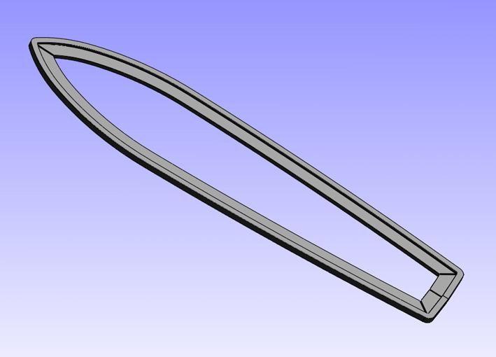
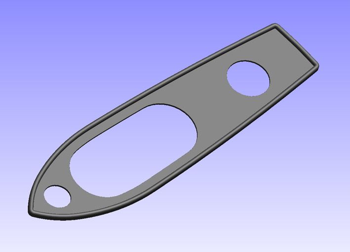
Location: SWITZERLAND | To be correct, here the Original Rear Antenna Gasket. I found a pair of Repros, not used, because they are too big (up to 3mm too long), the reason for the alternative. They are equal, although the base is not symmetric. Here the Original is exact to the corresponding base.
I feel this look "softer", but not applicable without removing the antenna. Just find another profile for the alternative. Compare and judge yourself on the second picture.
I added as well an eDrawing file of this Original Gasket, hopely the producer will use this for direct tooling. - SERGE -
Edited by sermey 2011-02-01 1:34 AM
 (01 CAD 1959 Original Rear Antenna Gasket.jpg) (01 CAD 1959 Original Rear Antenna Gasket.jpg)
 (02 CAD 1959 Comparison Rear Antenna Gaskets.jpg) (02 CAD 1959 Comparison Rear Antenna Gaskets.jpg)
Attachments
----------------
01 CAD 1959 Original Rear Antenna Gasket.jpg (53KB - 630 downloads)
02 CAD 1959 Comparison Rear Antenna Gaskets.jpg (86KB - 626 downloads)
Rear Antenna Original Gasket.EPRT (99KB - 597 downloads)
|
|
| |
|
Expert
Posts: 1208
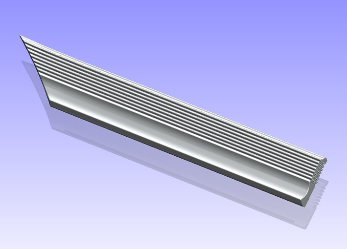
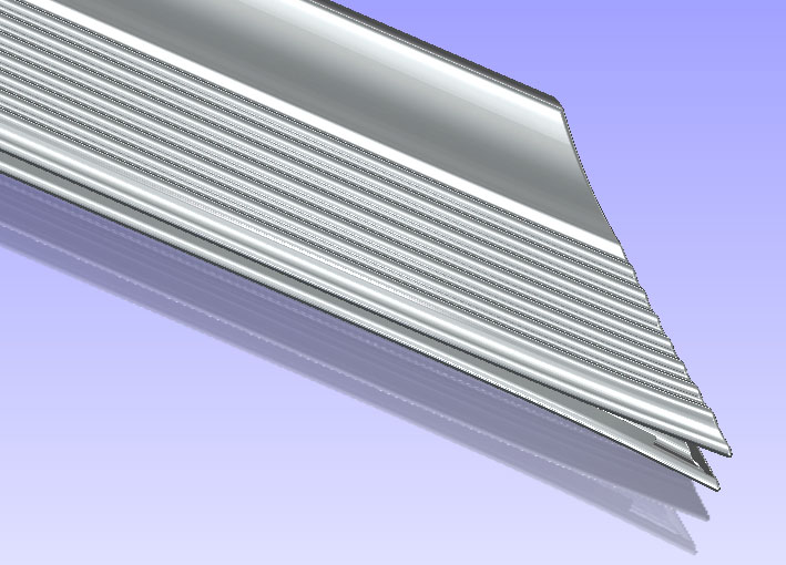
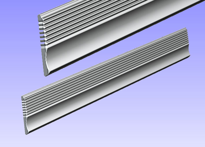
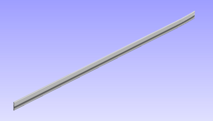
Location: SWITZERLAND | Among the three Side Mouldings, Front - Door - Rear, the Front one is particular due to the various end. The rear end of the Long Rear Moulding is as well curved in order to fit the fender. Apart this, the profile is simple and the length is just another number to program. For a 2- door car: 398mm - 1234mm - 2375mm, important to know when bidding in eBay! - SERGE -
 (01 CAD 1959 Front Moulding Front View.jpg) (01 CAD 1959 Front Moulding Front View.jpg)
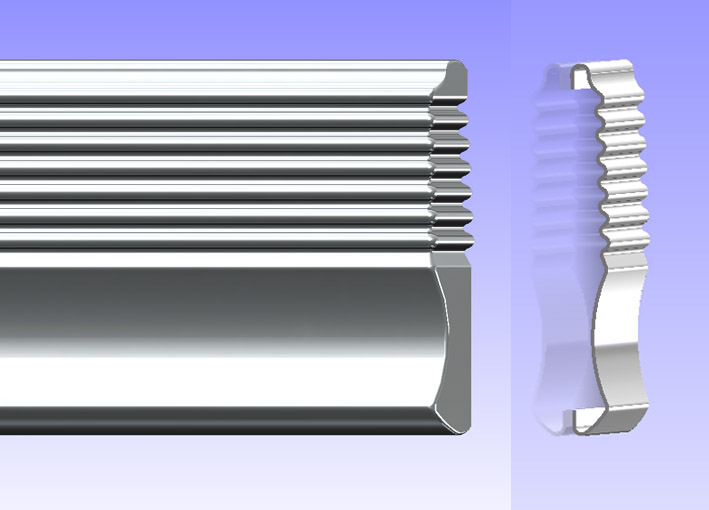 (02 CAD 1959 Side Moulding Profile.jpg) (02 CAD 1959 Side Moulding Profile.jpg)
 (03 CAD 1959 Front Moulding Curved End.jpg) (03 CAD 1959 Front Moulding Curved End.jpg)
 (04 CAD 1959 Front Moulding Other End 45deg.jpg) (04 CAD 1959 Front Moulding Other End 45deg.jpg)
 (05 CAD 1959 Door Moulding End 90deg.jpg) (05 CAD 1959 Door Moulding End 90deg.jpg)
 (06 CAD 1959 Door Moulding Matte Rear View.jpg) (06 CAD 1959 Door Moulding Matte Rear View.jpg)
 (07 CAD 1959 Long Rear Fender Moulding.jpg) (07 CAD 1959 Long Rear Fender Moulding.jpg)
Attachments
----------------
01 CAD 1959 Front Moulding Front View.jpg (65KB - 630 downloads)
02 CAD 1959 Side Moulding Profile.jpg (69KB - 593 downloads)
03 CAD 1959 Front Moulding Curved End.jpg (93KB - 632 downloads)
04 CAD 1959 Front Moulding Other End 45deg.jpg (73KB - 600 downloads)
05 CAD 1959 Door Moulding End 90deg.jpg (80KB - 616 downloads)
06 CAD 1959 Door Moulding Matte Rear View.jpg (70KB - 618 downloads)
07 CAD 1959 Long Rear Fender Moulding.jpg (45KB - 625 downloads)
|
|
| |
|
Expert
Posts: 1208
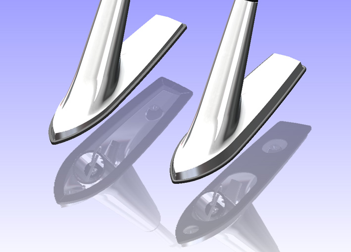
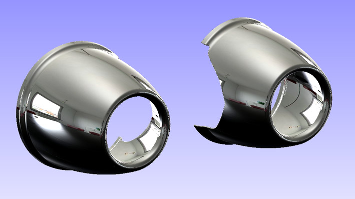
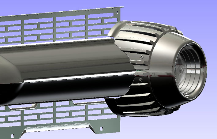
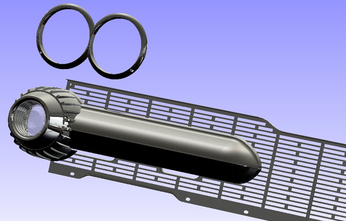
Location: SWITZERLAND | Not apparently on the car the slanted rear of the Front PositionLamp Bodies. Here I omitted the mounting brackets, much more complex and heavy than the body, not needed for my assembling to come.
Apart from that the shape is as the original. - SERGE -
 (01 CAD 1959 Bodies Front PositionLamp.jpg) (01 CAD 1959 Bodies Front PositionLamp.jpg)
 (02 CAD 1959 Bodies Side View.jpg) (02 CAD 1959 Bodies Side View.jpg)
 (03 CAD 1959 Bodies Rear View.jpg) (03 CAD 1959 Bodies Rear View.jpg)
Attachments
----------------
01 CAD 1959 Bodies Front PositionLamp.jpg (61KB - 620 downloads)
02 CAD 1959 Bodies Side View.jpg (48KB - 591 downloads)
03 CAD 1959 Bodies Rear View.jpg (55KB - 615 downloads)
|
|
| |
|
Board Moderator & Exner Expert 10K+
Posts: 13049
Location: Southern Sweden - Sturkö island | This thread is soo kool! Have you demounted the parts from your car, or do you measure on your spar parts Serge? |
|
| |
|
Regular
Posts: 95
Location: Espoo, Finland | Wow. I am working with a little project on my company, preprocessing point clouds from laser scanning data. It is amazing what new programs can do. If I only had possibility to use scanner and some time to play....
Those models are wonderful! Keep up the good work! |
|
| |
|
Expert
Posts: 1208
Location: SWITZERLAND | Wizard: Until now I used spare parts, and I didn't disaembled parts from the car jet. I don't have a spare Door Handle and will just model what is visible, as well with other parts. Later on I can add what is missing, as the mounting brackets on the Body of the Front PositionLamp. The exact position of the items for the assembling I measure on my car. As can be seen on some shown parts , the chrome is very shiny and on others not. When very shiny, the problem is mirroring the ambient, as when take pictures from chrome parts. Then the real shape is hardly visible. Thus, the shown Side Mouldings have removed ambient, or the mirroring profile will narrate. On the pictures you can easy recognize if there is a model or a real part, when inside a part there is unrealistic the same light and ambient. There I could add "matte chrome" as I did on the rear of the HubCap. This one looks amazing as an Original. JT Newman: By scanning parts you get a model with all blemishes of the part due to the production process and the non-linear shrinking of the molds. A reproduction using a scanned or impressed part will experience a second shrinking. In a new part the shrinking factor is taken into account by selecting the material. On the other side, a scanned part can as well be (up-) scaled. - SERGE -
Edited by sermey 2011-02-14 4:59 AM
|
|
| |
|
Expert
Posts: 1208
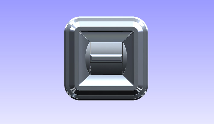
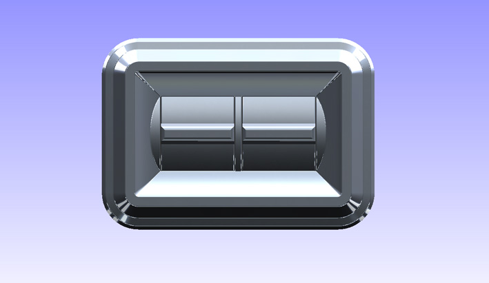
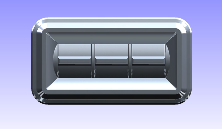
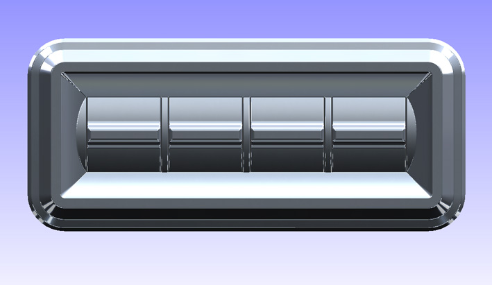
Location: SWITZERLAND | Before mounting my new Power Windows Switch I just put them in the Computer. Full geometrical devices, easy and fast to realise, even with all sizes 1 -2 - 3 - 4. I never saw a 3 Switch one, so could even do a 5 Switch item. Here I present only the Front View of the four Versions. - SERGE - For the freaks I have attached an eDrawing file with the single and quadro version (just the front due to file size) for play with. Now I have downloaded this pre-checked file, the remaining file name has to be renamed with the extension .EPRT (CAD -> CAD.EPRT). You may need to upgrade your eDrawing-Viewer to 2011 (for free in Internet). Please some feedback. Thanks.
Edited by sermey 2011-02-14 4:57 PM
 (01 CAD 1959 Power Windows Switch.jpg) (01 CAD 1959 Power Windows Switch.jpg)
 (02 CAD 1959 Power Windows Switch.jpg) (02 CAD 1959 Power Windows Switch.jpg)
 (03 CAD 1959 Power Windows Switch.jpg) (03 CAD 1959 Power Windows Switch.jpg)
 (04 CAD 1959 Power Windows Switch.jpg) (04 CAD 1959 Power Windows Switch.jpg)
Attachments
----------------
01 CAD 1959 Power Windows Switch.jpg (49KB - 613 downloads)
02 CAD 1959 Power Windows Switch.jpg (55KB - 585 downloads)
03 CAD 1959 Power Windows Switch.jpg (61KB - 626 downloads)
04 CAD 1959 Power Windows Switch.jpg (68KB - 605 downloads)
CAD 1959 Power Windows Switch.EPRT (214KB - 590 downloads)
|
|
| |
|
Expert
Posts: 1208
Location: SWITZERLAND | . . . Apart from that the shape is as the original. . . No, when assembling with the collar I saw one step wasn't cut-out on the lower side. Just cut both in one operation. I think this is for not touch the Front Bumper or for tighten the screws. Not nice, could even remove in the model.
Edited by sermey 2011-02-18 10:32 AM
 (04 CAD 1959 Front PositionLamp.jpg) (04 CAD 1959 Front PositionLamp.jpg)
Attachments
----------------
04 CAD 1959 Front PositionLamp.jpg (64KB - 594 downloads)
|
|
| |
|
Expert
Posts: 1208
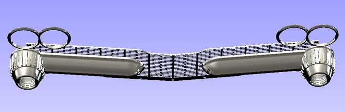
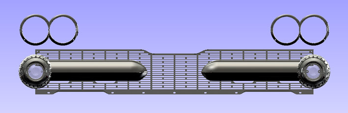
Location: SWITZERLAND | After completing the Front Bar I can present a first Assembly of the Front. I removed the shown Step Cut, as well on the lower side of the Front Bar, for a nicer aspect. In the Computer all is done with real dimensions 1 :1. For the first time, the owners of a 1959 Dodge can check if their Front Components are aligned correctly. - SERGE - 
Edited by sermey 2011-02-19 3:24 PM
 (01 CAD 1959 Front in Perspective.jpg) (01 CAD 1959 Front in Perspective.jpg)
 (02 CAD 1959 Front Detail View.jpg) (02 CAD 1959 Front Detail View.jpg)
 (03 CAD 1959 Front Top View.jpg) (03 CAD 1959 Front Top View.jpg)
 (04 CAD 1959 Other Detail View.jpg) (04 CAD 1959 Other Detail View.jpg)
 (05 CAD 1959 Exact Front View.jpg) (05 CAD 1959 Exact Front View.jpg)
Attachments
----------------
01 CAD 1959 Front in Perspective.jpg (82KB - 618 downloads)
02 CAD 1959 Front Detail View.jpg (84KB - 591 downloads)
03 CAD 1959 Front Top View.jpg (53KB - 612 downloads)
04 CAD 1959 Other Detail View.jpg (86KB - 603 downloads)
05 CAD 1959 Exact Front View.jpg (53KB - 596 downloads)
|
|
| |
|
Board Moderator & Exner Expert 10K+
Posts: 13049
Location: Southern Sweden - Sturkö island | Kool Serge, will you do the sheetmetal as well? A body in white (raw metal) perhaps? |
|
| |
|
Expert
Posts: 1208
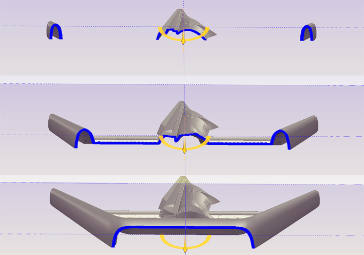
Location: SWITZERLAND | wizard - 2011-02-19 10:11 PM . . . will you do the sheetmetal as well? . . . The objective is to have one day all the complete car, what is visible. The biggest job (games!) are all the parts around the car, what I am doing now. Every part is a single project. The body (sheetmetall) will be a small thing in respect to the Knight Head or other complex parts. This will be one single "cover", then being splitted in Trunk, Doors, Hood. For now I already assemble the existing parts at the correct location, "floating in the air" - these parts are "waiting" for the body. What doesn't exist jet can be added by imagination.
At the end any color combination can be realized, even in wood, in stone, any material. All the car can be scaled, transformed, stretched . . . whatever by a few commands, keeping all in 3D-RealView. Then the car can be placed in any 3D-environment, there will hardly be a difference between reality and animation. This will be the end of the game or - then the real game starts! - SERGE -
|
|
| |
|
Expert
Posts: 1208
Location: SWITZERLAND | I didn't showed the other side of the Power Windows Switch with the Mounting Bracket - to complete here it is. - SERGE -
Edited by sermey 2011-02-22 1:12 PM
 (05 CAD 1959 Power Windows Switch.jpg) (05 CAD 1959 Power Windows Switch.jpg)
 (06 CAD 1959 Power Windows Switch.jpg) (06 CAD 1959 Power Windows Switch.jpg)
 (07 CAD 1959 Power Windows Switch.jpg) (07 CAD 1959 Power Windows Switch.jpg)
Attachments
----------------
05 CAD 1959 Power Windows Switch.jpg (73KB - 598 downloads)
06 CAD 1959 Power Windows Switch.jpg (63KB - 613 downloads)
07 CAD 1959 Power Windows Switch.jpg (68KB - 589 downloads)
|
|
| |
|
Board Moderator & Exner Expert 10K+
Posts: 13049
Location: Southern Sweden - Sturkö island | Special thank's for posting those ones Serge, they look next to identical to the '60 ones from the backside. |
|
| |
|
Expert
Posts: 1208
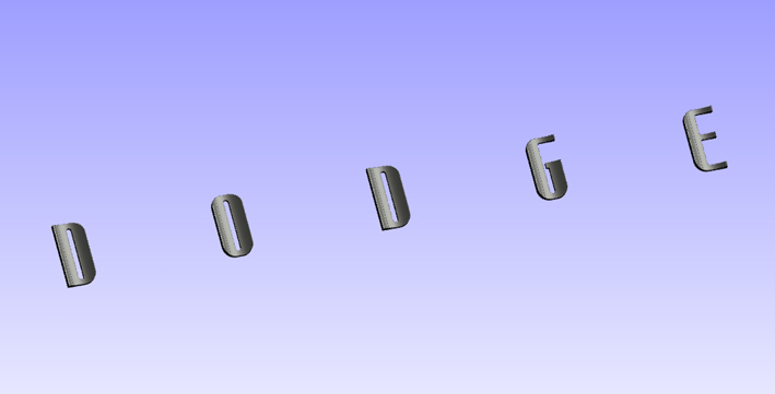
Location: SWITZERLAND | The Rear "D O D G E" Letters mounted on the Trunk have been done in one block, with the correct distance, for an easy assembling. Without any details primarly very easy and fast to realize. But then the pattern of the borders, with the many fillets, finally needed alone about 50 (fifty) times more memory, the file size has grown up to 49MB (Mega).
That's Design! - SERGE -
Edited by sermey 2011-02-25 6:35 AM
 (01 CAD 1959 DODGE Letters Front View.jpg) (01 CAD 1959 DODGE Letters Front View.jpg)
 (02 CAD 1959 Letter D Front View Zoomed.jpg) (02 CAD 1959 Letter D Front View Zoomed.jpg)
 (03 CAD 1959 DODGE Letters Rear View.jpg) (03 CAD 1959 DODGE Letters Rear View.jpg)
 (04 CAD 1959 Letter D Rear View Zoomed.jpg) (04 CAD 1959 Letter D Rear View Zoomed.jpg)
 (05 CAD 1959 DODGE Letters on Black Car.jpg) (05 CAD 1959 DODGE Letters on Black Car.jpg)
Attachments
----------------
01 CAD 1959 DODGE Letters Front View.jpg (75KB - 588 downloads)
02 CAD 1959 Letter D Front View Zoomed.jpg (67KB - 584 downloads)
03 CAD 1959 DODGE Letters Rear View.jpg (45KB - 590 downloads)
04 CAD 1959 Letter D Rear View Zoomed.jpg (66KB - 598 downloads)
05 CAD 1959 DODGE Letters on Black Car.jpg (22KB - 603 downloads)
|
|
| |
|
Expert
Posts: 1208
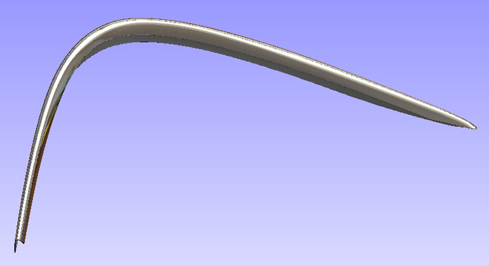
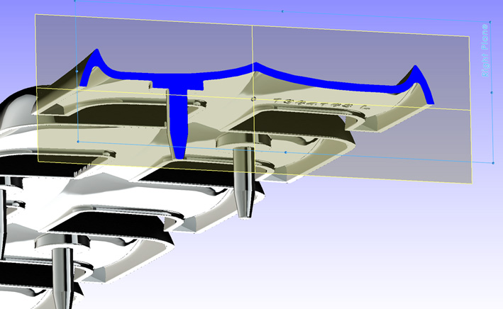
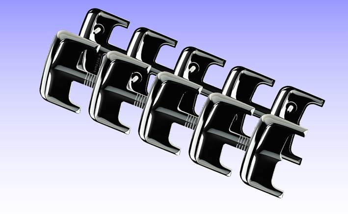
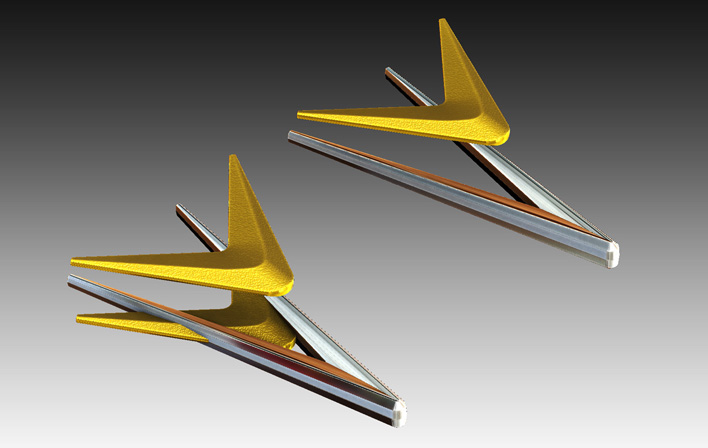
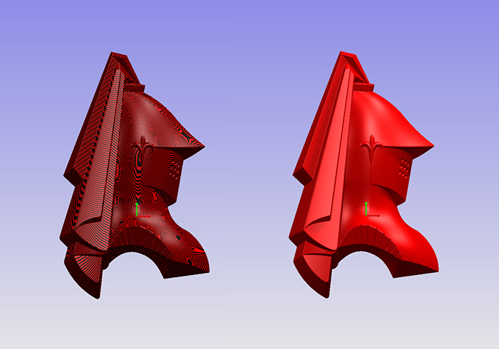
Location: SWITZERLAND | Among '59 Dodge owners, this part is well-known as "EyeBrow". If they had 3D-CAD in the fifties, this part would have been designed per shure different, with less twist, curvature and bend. I will have to do a fine fitting to the sheet metall when assembling for no gaps at all - as on my DODGE! - SERGE -
 (01 CAD 1959 EyeBrow Front View.jpg) (01 CAD 1959 EyeBrow Front View.jpg)
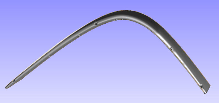 (02 CAD 1959 EyeBrow Rear View.jpg) (02 CAD 1959 EyeBrow Rear View.jpg)
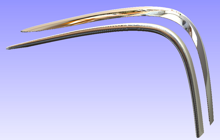 (03 CAD 1959 Pair of EyeBrows.jpg) (03 CAD 1959 Pair of EyeBrows.jpg)
Attachments
----------------
01 CAD 1959 EyeBrow Front View.jpg (52KB - 596 downloads)
02 CAD 1959 EyeBrow Rear View.jpg (48KB - 615 downloads)
03 CAD 1959 Pair of EyeBrows.jpg (77KB - 589 downloads)
|
|
| |
|
Expert
Posts: 1208
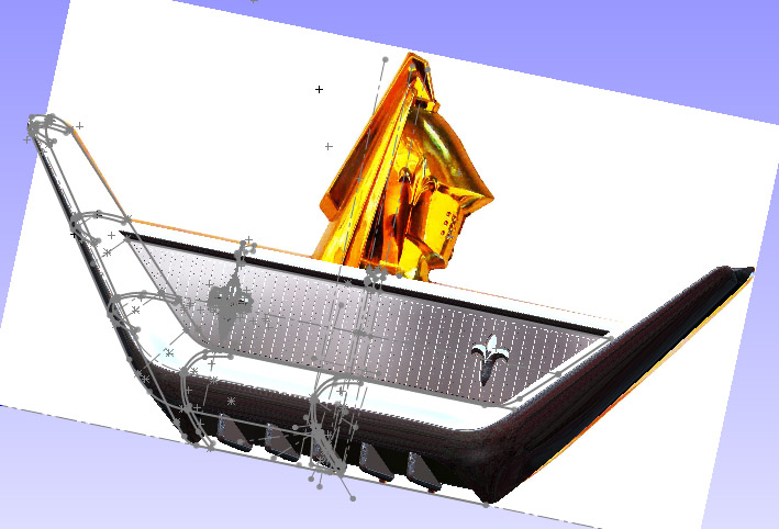
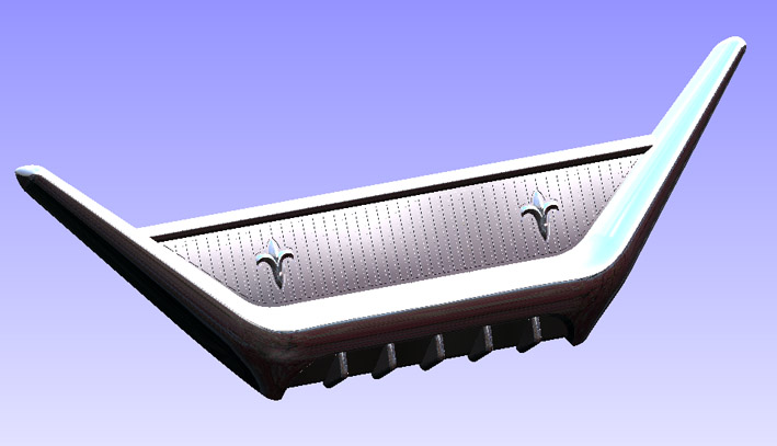
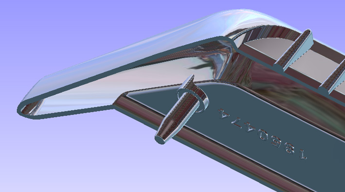
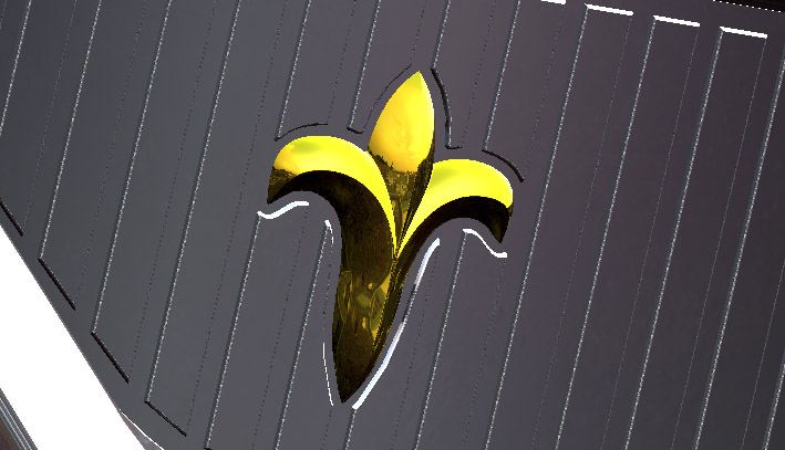
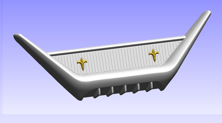
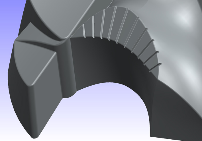
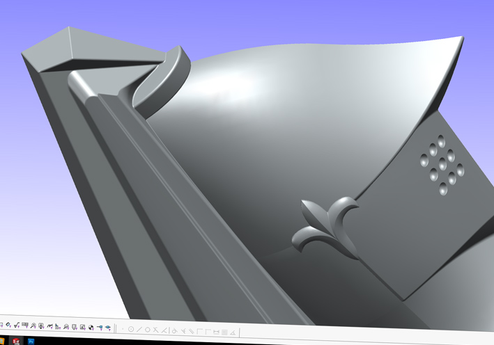
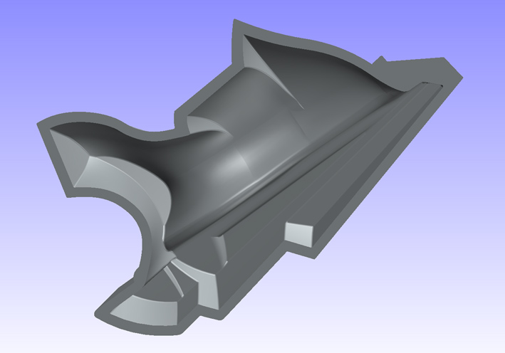
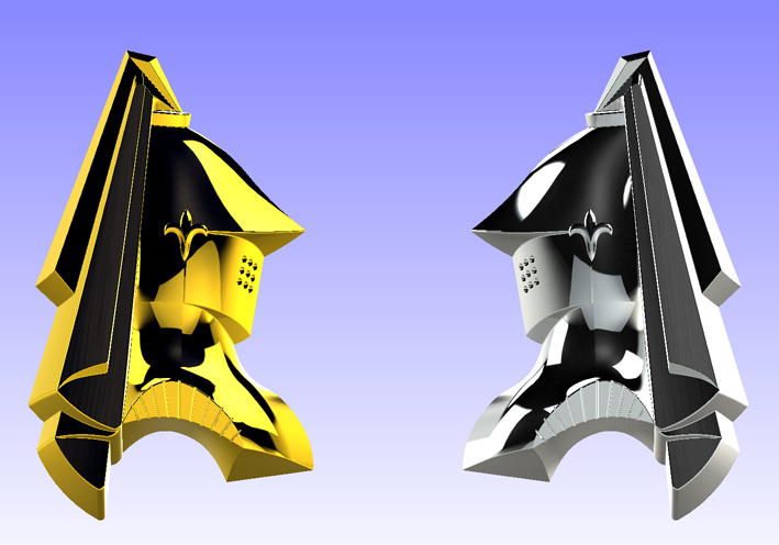
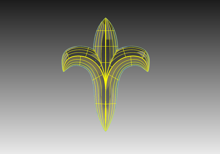
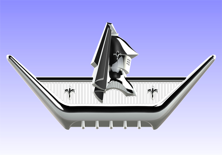
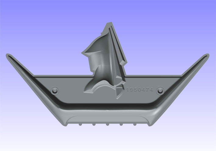
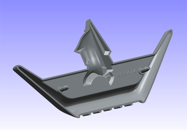
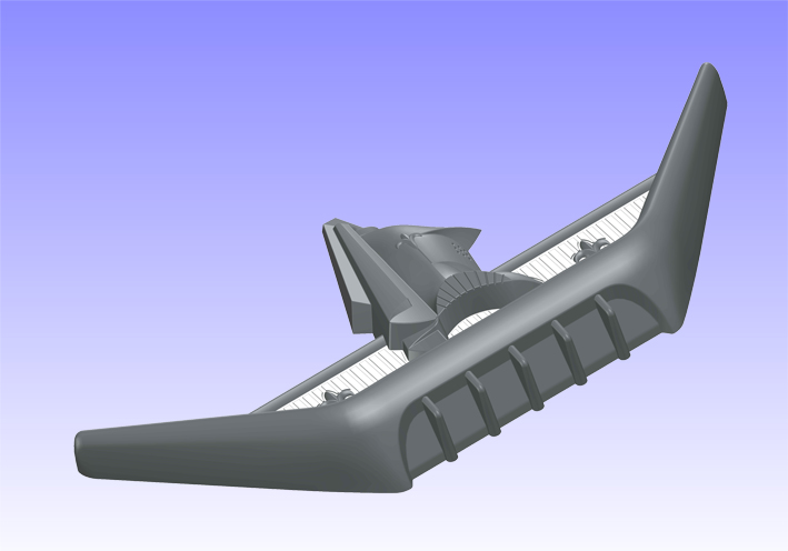
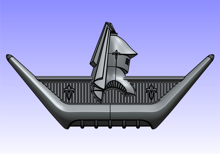
Location: SWITZERLAND | This Rear Emblem comes on the trunk of the Custom Royal, on the Coronets there are two on the fender front sides. For technical interested Readers I show shortly how this body is being modeled. Take a picture size 1:1 as base reference, draw five sections for the left arm, loft them along 3 guides and mirror this half to get the entire body. This as well for the flower emblem: left and center part, mirror this as to get the complete flower, and mirror all again to get it twice. Loft the upper small bar at constant profile, extrude the panel with the given profile, extrude the lower Dent and array it 5 times. That's all! All other is the finish. Some items are shown matte for no mirror irritations. The knight, being used as well for other Emblems to come, will be done separate and shown later. – SERGE -
 (01 CAD 1959 Design Detail.jpg) (01 CAD 1959 Design Detail.jpg)
 (02 CAD 1959 Chrome Front View.jpg) (02 CAD 1959 Chrome Front View.jpg)
 (03 CAD 1959 Chrome Bottom View.jpg) (03 CAD 1959 Chrome Bottom View.jpg)
 (04 CAD 1959 Golden Flower.jpg) (04 CAD 1959 Golden Flower.jpg)
 (05 CAD 1959 Matte Rear View.jpg) (05 CAD 1959 Matte Rear View.jpg)
 (06 CAD 1959 Matte Front View.jpg) (06 CAD 1959 Matte Front View.jpg)
Attachments
----------------
01 CAD 1959 Design Detail.jpg (108KB - 598 downloads)
02 CAD 1959 Chrome Front View.jpg (67KB - 598 downloads)
03 CAD 1959 Chrome Bottom View.jpg (86KB - 612 downloads)
04 CAD 1959 Golden Flower.jpg (84KB - 615 downloads)
05 CAD 1959 Matte Rear View.jpg (56KB - 623 downloads)
06 CAD 1959 Matte Front View.jpg (65KB - 581 downloads)
|
|
| |
|
Expert
Posts: 1208
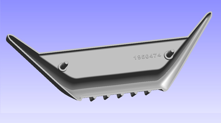
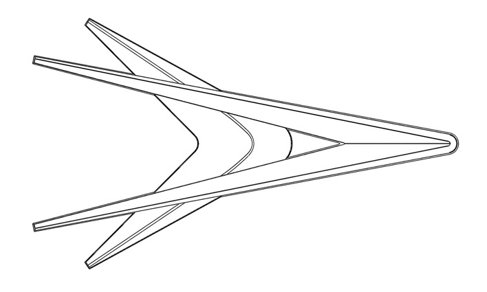
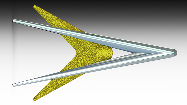
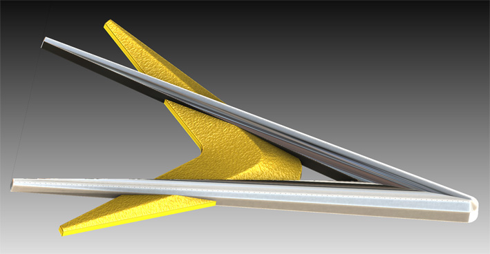
Location: SWITZERLAND | The Chevron Emblems are mounted on the rear fenders, thus there have two different ones, the one for the left side and the other for the right side, with different part numbers. At the first glance they look equal. But the lower side, seen when mounted, is about 1.5mm higher. Here I modeled both items symmetric, the mounting pins being mirrored as on the samples. The original emblems have various thickness, and the wings differs from the others in details – the wellknown tolerances at the time. A reproduction by from a 3D-scan of these parts could be critical. Now I can state, this Chevron Emblem has never been illustrated as nice and perfect as on the shown pictures here. – SERGE -
Edited by sermey 2014-04-17 5:29 PM
 (01 Front View 25.jpg) (01 Front View 25.jpg)
 (02 Part Number 25.jpg) (02 Part Number 25.jpg)
 (03 Section View 25.jpg) (03 Section View 25.jpg)
 (04 View R + L 25.jpg) (04 View R + L 25.jpg)
 (05 Side View 25.jpg) (05 Side View 25.jpg)
 (06 Top View 25.jpg) (06 Top View 25.jpg)
 (07 Top View Flat 25.jpg) (07 Top View Flat 25.jpg)
Attachments
----------------
01 Front View 25.jpg (79KB - 618 downloads)
02 Part Number 25.jpg (69KB - 584 downloads)
03 Section View 25.jpg (94KB - 602 downloads)
04 View R + L 25.jpg (89KB - 601 downloads)
05 Side View 25.jpg (78KB - 608 downloads)
06 Top View 25.jpg (72KB - 593 downloads)
07 Top View Flat 25.jpg (83KB - 596 downloads)
|
|
| |
|
Expert
Posts: 4042
Location: Connecticut | Would you be able to someday output these files to a 3D printer and produce finished copies, ready to be mounted ? Note: Coronet had a nameplate that read 'Coronet' on front fender. Only the station wagons and Silver Challenger had the trunk medallion on the fenders. Are you fancying things up a bit by making the knight's head gold ? Ron |
|
| |
|
Board Moderator & Exner Expert 10K+
Posts: 13049
Location: Southern Sweden - Sturkö island | Dedicated as always Serge, that took you some time to create I imagine - real hardcore for the '59 Dodge entusiasts |
|
| |
|
Expert
Posts: 1208
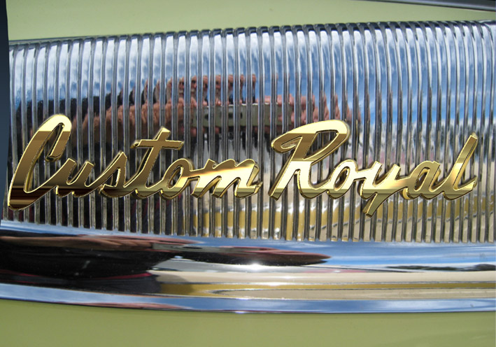
Location: SWITZERLAND | There are two scripts “Custom Royal”, on the left and the right side of the car. They are made in golden anodized Aluminium. Because letters cannot be mirrored, both scripts are identical. A picture and/or better a scan on the flatbed scanner gives a useful reference contour. Before using, it must be aligned to fit to the real measured values. The picture 01 shows the "aligned" script, the verticals of the support becoming straight and the sheetmetall underneath rounded. As these emblems varies in details from one to the other, the letters of the reference sketch have to be optimized – what needs the most time. Once the result is satisfying by visual control, then the proceeding is simple. Finally, the modeled scripts have to be deformed to the bodys curved surface. CAD made this easy, but by processing the computer goes quite busy. The mounting pins are missing and not modeled here. Another golden eye-catcher, upgrading the 1959 Dodge Custom Royal to its exclusivity - SERGE -
Edited by sermey 2014-04-21 2:56 PM
 (01 Model on Picture 25.jpg) (01 Model on Picture 25.jpg)
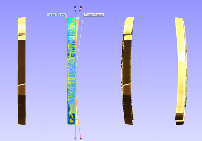 (02 Deforming to Body 25.jpg) (02 Deforming to Body 25.jpg)
 (03 Rear Details 25.jpg) (03 Rear Details 25.jpg)
 (04 3D-Script Custom Royal 25.jpg) (04 3D-Script Custom Royal 25.jpg)
 (05 3D Dual View 25.jpg) (05 3D Dual View 25.jpg)
Attachments
----------------
01 Model on Picture 25.jpg (146KB - 694 downloads)
02 Deforming to Body 25.jpg (67KB - 690 downloads)
03 Rear Details 25.jpg (81KB - 668 downloads)
04 3D-Script Custom Royal 25.jpg (58KB - 685 downloads)
05 3D Dual View 25.jpg (84KB - 686 downloads)
|
|
| |
|
Expert
Posts: 1208
Location: SWITZERLAND | ronbo97 - 2014-04-17 10:02 PM Would you be able to someday output these files to a 3D printer and produce finished copies, ready to be mounted ? Note: Coronet had a nameplate that read 'Coronet' on front fender. Only the station wagons and Silver Challenger had the trunk medallion on the fenders. Are you fancying things up a bit by making the knight's head gold ? Ron Ron, if you send me the exact contour of the nameplate "Coronet", I can do this for you (JPG or PDF). These files, converted to .STEP or .STL as used in the industry, can directly be used for Tooling or 3D-Printing. Last process is still not enough exact for small parts. The Golden Knight Head is still on my "program", but it must be done perfectly. |
|
| |
|
Expert
Posts: 4042
Location: Connecticut | Serge - I will shoot some high quality images for you and email to your bluewin.ch email address. I'll include a ruler for scale. Ron |
|
| |
|
Expert
Posts: 1208
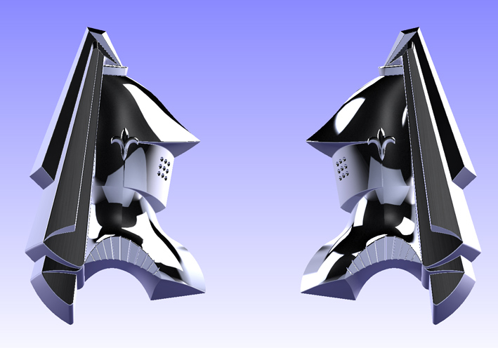
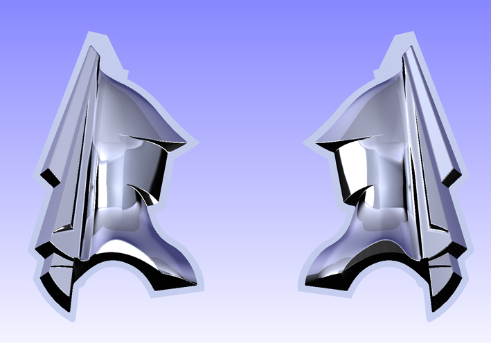
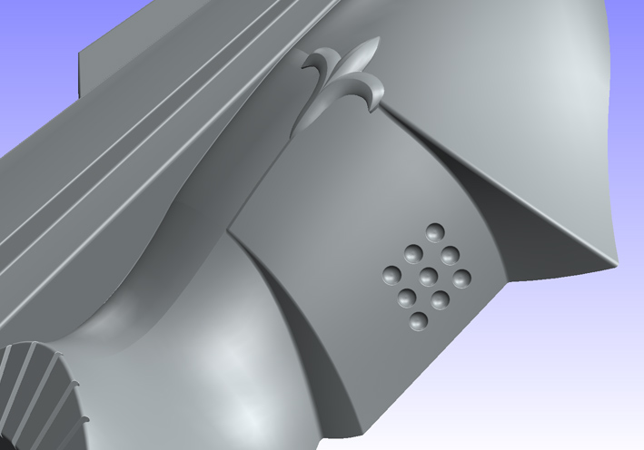
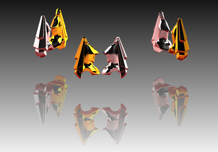
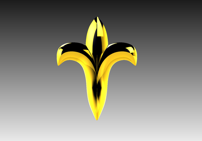
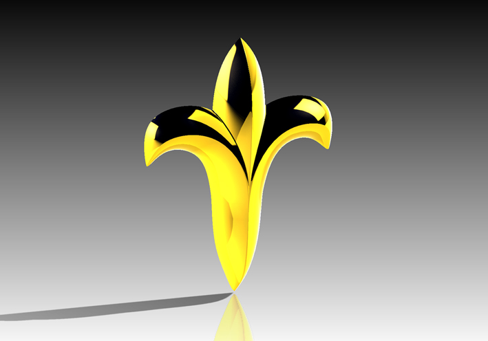
Location: SWITZERLAND | FWL Emblem: This emblem is not a 1959 Dodge part. But I am fascinating of this design. Here some variations in 3D-RealView. All fantastic combinations can be done. But for another time. - SERGE -
 (01 FWL Emblem.jpg) (01 FWL Emblem.jpg)
 (02 FWL Emblem.jpg) (02 FWL Emblem.jpg)
 (03 FWL Emblem.jpg) (03 FWL Emblem.jpg)
 (04 FWL Emblem Dual.jpg) (04 FWL Emblem Dual.jpg)
Attachments
----------------
01 FWL Emblem.jpg (50KB - 727 downloads)
02 FWL Emblem.jpg (135KB - 668 downloads)
03 FWL Emblem.jpg (76KB - 671 downloads)
04 FWL Emblem Dual.jpg (77KB - 682 downloads)
|
|
| |
|
Expert 5K+
Posts: 5006
| So they can be 3d printed? |
|
| |
|
Expert
Posts: 1208
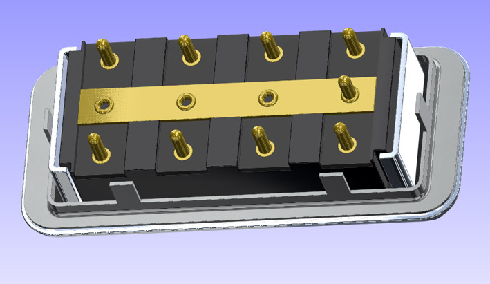
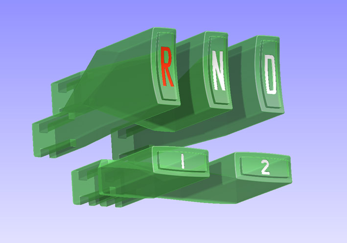
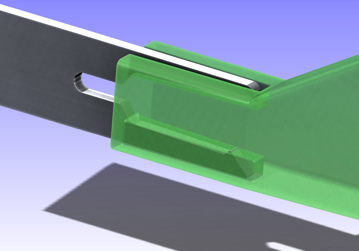
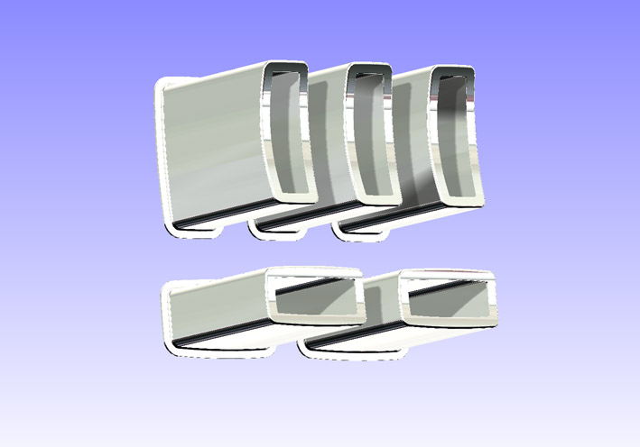
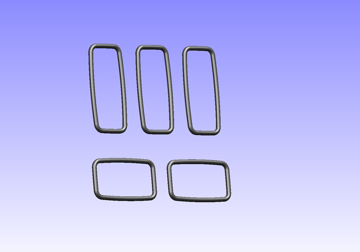
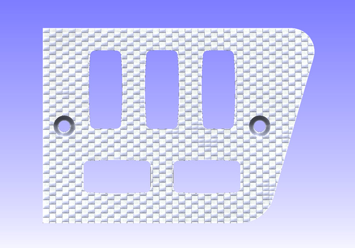
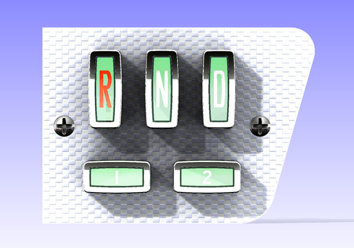
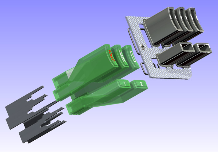
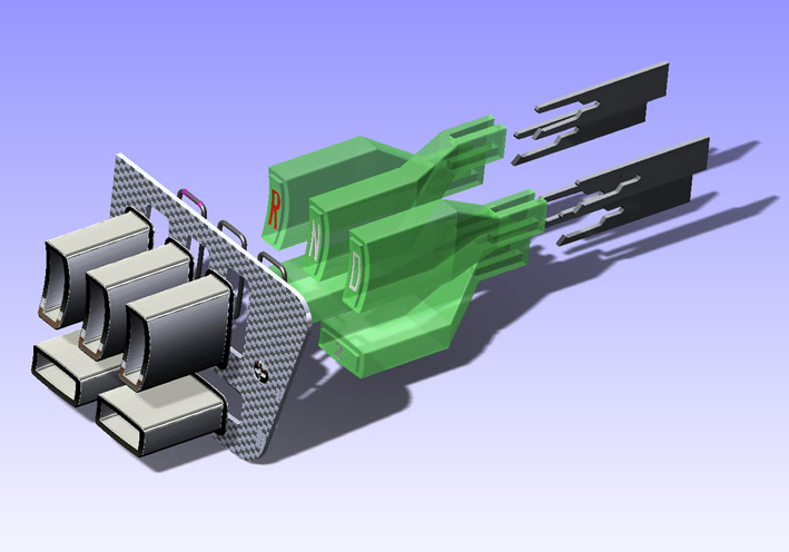
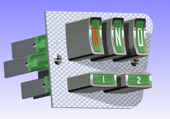
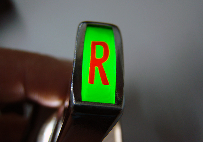
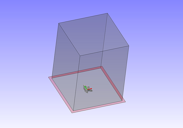
Location: SWITZERLAND | Push Button Unit: The gear in the automatic torqueflite transmission is set by five push buttons R – N – D – 1 – 2 . These are moulded parts in green transparent plastic, the letters are graved and colored with paint (01). These buttons are just shifted on to the rear mechanical unit. The transparency shows exact the original conical design (02). The protecting chrome cups are pushed on the buttons (03). For a smoother return, O-rings are provided as dampener (04). Finally, the patterned and polished aluminium panel is mounted and fixed by two screws (05). As the buttons are in transparent plastic, with rear light they appear illuminated (06). In the exploded views all parts are visible (07)(08). Here the push button unit as it is – in 3D-RealView. Any questions? Yes, with the STL-files of the present design these push buttons could be reproduced exactly with a 3D Printer, even the green transparent 3D Filament is now available. - SERGE -
Edited by sermey 2016-10-18 11:55 PM
 (01 CAD 1959 Push Buttons R-N-D-1-2.jpg) (01 CAD 1959 Push Buttons R-N-D-1-2.jpg)
 (02 CAD 1959 Rear Connection.jpg) (02 CAD 1959 Rear Connection.jpg)
 (03 CAD 1959 Chrome Cups.jpg) (03 CAD 1959 Chrome Cups.jpg)
 (04 CAD 1959 Rubber Dampener.jpg) (04 CAD 1959 Rubber Dampener.jpg)
 (05 CAD 1959 Patterned Alu-Panel.jpg) (05 CAD 1959 Patterned Alu-Panel.jpg)
 (06 CAD 1959 Assembly FrontView Illuminated.jpg) (06 CAD 1959 Assembly FrontView Illuminated.jpg)
 (07 CAD 1959 Assembly Exploded SideView.jpg) (07 CAD 1959 Assembly Exploded SideView.jpg)
 (08 CAD 1959 Assembly Exploded TopView.jpg) (08 CAD 1959 Assembly Exploded TopView.jpg)
 (09 CAD 1959 Push Buttons Unit.jpg) (09 CAD 1959 Push Buttons Unit.jpg)
Attachments
----------------
01 CAD 1959 Push Buttons R-N-D-1-2.jpg (61KB - 575 downloads)
02 CAD 1959 Rear Connection.jpg (57KB - 601 downloads)
03 CAD 1959 Chrome Cups.jpg (59KB - 601 downloads)
04 CAD 1959 Rubber Dampener.jpg (46KB - 584 downloads)
05 CAD 1959 Patterned Alu-Panel.jpg (111KB - 586 downloads)
06 CAD 1959 Assembly FrontView Illuminated.jpg (99KB - 580 downloads)
07 CAD 1959 Assembly Exploded SideView.jpg (77KB - 585 downloads)
08 CAD 1959 Assembly Exploded TopView.jpg (78KB - 577 downloads)
09 CAD 1959 Push Buttons Unit.jpg (108KB - 600 downloads)
|
|
| |
|
Board Moderator & Exner Expert 10K+
Posts: 13049
Location: Southern Sweden - Sturkö island | This is amazing Serge - it must have taken many hours of measuring and creating the pushbuttons.  |
|
| |
|
Elite Veteran
Posts: 1159
Location: D-70199 Heslach | Serge, I like to print the FWL Emblem.... |
|
| |
|
Expert
Posts: 1208
Location: SWITZERLAND | Sven: . . . . it must have taken many hours of measuring and creating the pushbuttons . . . . As the software is parametric, the exact dimensions are re-measured and corrected at the end of the modeling process. And for those who are familiar with: This is not an assembly of parts as usual, but a multipart design. I use to do a mastersketch, one or two views referring to all parts. Later the dimensions can be modified here, means that all parts are in one single file .sldprt, and in the sketched position, except when "exploded". Equal items are modeled together, or mirrored, arrayed and copied if needed. - SERGE -
Edited by sermey 2016-10-19 2:51 AM
|
|
| |
|
Member
Posts: 33
| Serge, as one who works with architectural CAD every day, my hat is off to you. These are stunning!! |
|
| |
|
Expert
Posts: 1208
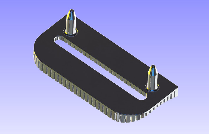
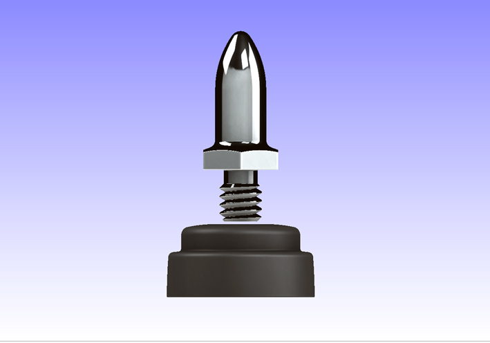
Location: SWITZERLAND | Convertible Top Pin – Grommet: Devices to center and seal the top when up, in the parts catalogue as “catch and seal”. The easiest part until now to model. Just needed the correct dimensions of the grommet. Here some pictures in 3D-RealView. - SERGE -
 (01 Bottom Up Exploded View.jpg) (01 Bottom Up Exploded View.jpg)
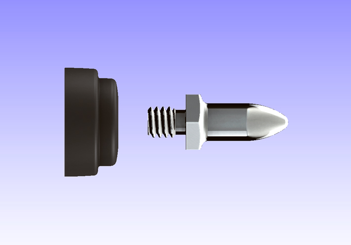 (02 Horizontal Exploded View.jpg) (02 Horizontal Exploded View.jpg)
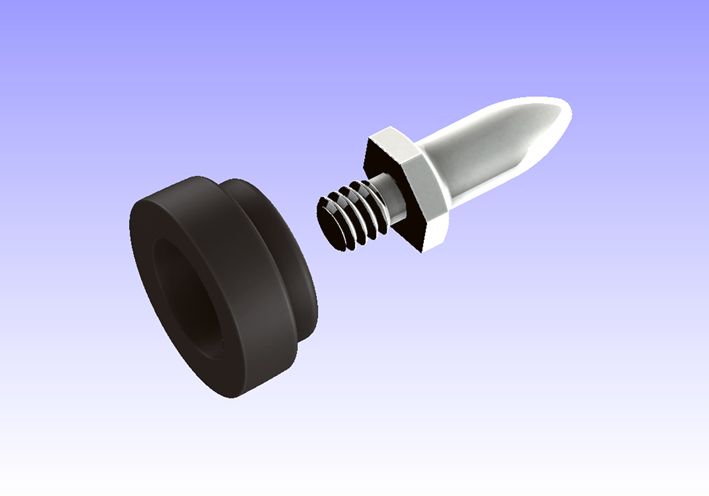 (03 3D Exploded View.jpg) (03 3D Exploded View.jpg)
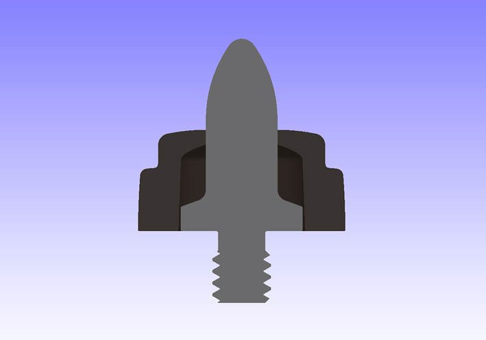 (04 Assembled Section View.jpg) (04 Assembled Section View.jpg)
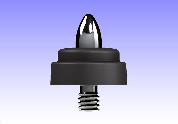 (05 Assembled.jpg) (05 Assembled.jpg)
Attachments
----------------
01 Bottom Up Exploded View.jpg (74KB - 477 downloads)
02 Horizontal Exploded View.jpg (71KB - 460 downloads)
03 3D Exploded View.jpg (81KB - 463 downloads)
04 Assembled Section View.jpg (59KB - 454 downloads)
05 Assembled.jpg (82KB - 460 downloads)
|
|
| |
|
Expert
Posts: 1208
Location: SWITZERLAND | "Serge, as one who works with architectural CAD every day, my hat is off to you. These are stunning!!" Thanks for your comment, Dean. Some are more spectacular, this last is very easy: just revolve the profile. - SERGE -
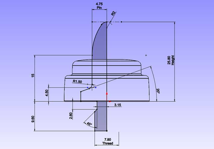 (MasterSketch Revolve.jpg) (MasterSketch Revolve.jpg)
Attachments
----------------
MasterSketch Revolve.jpg (129KB - 464 downloads)
|
|
| |
|
Expert
Posts: 1208
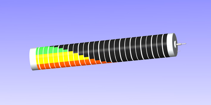
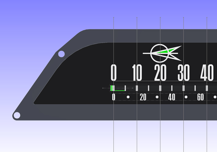
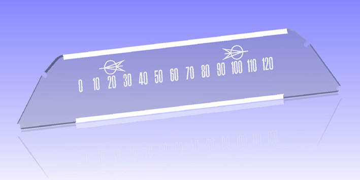
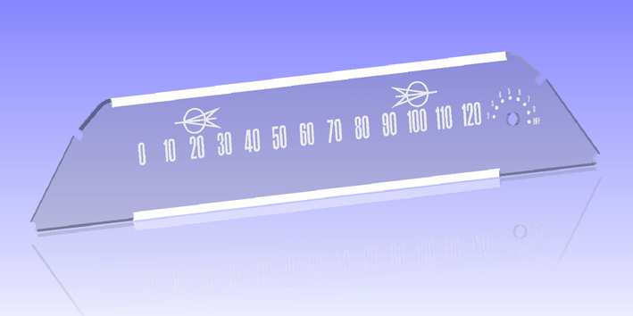
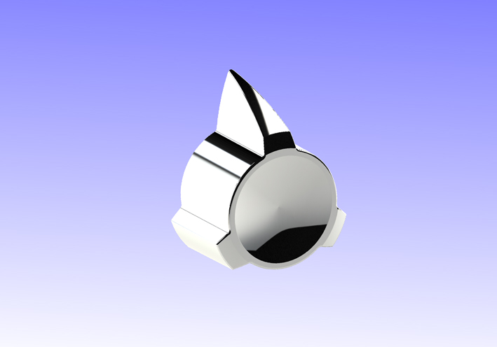
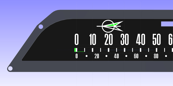
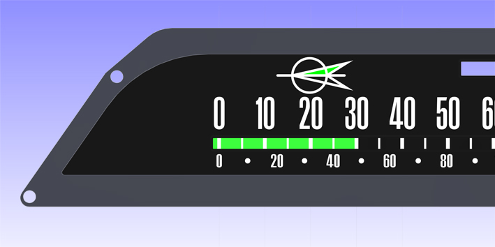
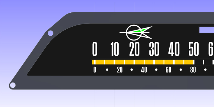
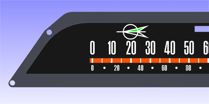
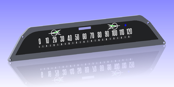
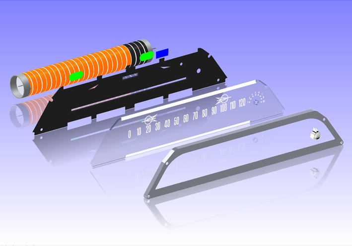
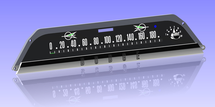
Location: SWITZERLAND | The reference for numbering the speedometer scale is the drum, as it is lateral fixed and cannot be moved. Thus, the distances of the scale numbers have to be positioned and centered according the lines (01). Total distance for any 10mph is 18.583mm, the numbering length for 140mph (center to center) is 223mm. The original scale is somewhat mismatched, now the numbers are aligned to the speedometer drum (02). The letters and the directional emblems on the original glass are engraved backside and whitened. The upper and lower white stripe support the illumination (03). The glass version with the speed reminder option has an additional scale which is printed (04). The setting knob here looks like a lonely bird flying in the sky (05). At the speed of 0mph the first green bar is just (not-) visible at correct setting (06). Up to 30mph the bar is GREEN (07), from 30 – 50mph turns to YELLOW (08), and higher than 50mph up shows RED (09). The assembly is shown in (10). On the exploded view, the rear metal panel in black and the colored tabs, green and blue for the light signals, are brought out (11). Finally, the correct and direct interchangeable Speedometer Scale in kmph, 0 – 180 (120mph = 193.08kmph). 200 is out of the range and would interfere with the Speed Reminder Scale. Compressing the scale to 200 to coincide to 120 needs a recalibration. For completing, the front chrome bar D O D G E (12). - SERGE - More options and printable templates will be presented in the thread “Make-up your car”.
Edited by sermey 2018-04-24 5:47 AM
 (01 Speedometer Drum.jpg) (01 Speedometer Drum.jpg)
 (02 Alignment of the Numbers.jpg) (02 Alignment of the Numbers.jpg)
 (03 Glass 0 - 120mph.jpg) (03 Glass 0 - 120mph.jpg)
 (04 Glass 0 - 120mph with Speed Reminder.jpg) (04 Glass 0 - 120mph with Speed Reminder.jpg)
 (05 Speed Reminder Knob.jpg) (05 Speed Reminder Knob.jpg)
 (06 0mph GREEN just visible.jpg) (06 0mph GREEN just visible.jpg)
 (07 GREEN up to 30mph.jpg) (07 GREEN up to 30mph.jpg)
 (08 YELLOW 30 - 50mph.jpg) (08 YELLOW 30 - 50mph.jpg)
 (09 RED 50mph up.jpg) (09 RED 50mph up.jpg)
 (10 Assembly 0 - 120mph.jpg) (10 Assembly 0 - 120mph.jpg)
 (11 Assembly Exploded View.jpg) (11 Assembly Exploded View.jpg)
 (12 Assembly 0 - 180kmph.jpg) (12 Assembly 0 - 180kmph.jpg)
Attachments
----------------
01 Speedometer Drum.jpg (95KB - 438 downloads)
02 Alignment of the Numbers.jpg (112KB - 444 downloads)
03 Glass 0 - 120mph.jpg (105KB - 447 downloads)
04 Glass 0 - 120mph with Speed Reminder.jpg (107KB - 434 downloads)
05 Speed Reminder Knob.jpg (98KB - 443 downloads)
06 0mph GREEN just visible.jpg (93KB - 438 downloads)
07 GREEN up to 30mph.jpg (94KB - 447 downloads)
08 YELLOW 30 - 50mph.jpg (90KB - 428 downloads)
09 RED 50mph up.jpg (93KB - 443 downloads)
10 Assembly 0 - 120mph.jpg (104KB - 432 downloads)
11 Assembly Exploded View.jpg (175KB - 440 downloads)
12 Assembly 0 - 180kmph.jpg (120KB - 436 downloads)
|
|
| |
|
Board Moderator & Exner Expert 10K+
Posts: 13049
Location: Southern Sweden - Sturkö island | Our Serge at work again, leaving us all impressed and amazed!
Very nice idea with the combined km/h and mph
The exploded view is totally great help for insight and knowledge!!! |
|
| |
|

Expert 5K+
Posts: 6500
Location: Newark, Texas (Fort Worth) | Absolutely amazing! Has 3D caught up now? I see YouTube videos of very smooth 'prints' from share ware or whatever it is called. It then can be molded in silicone and cast in wax and then molded in a plaster mold with metal like white bronze. You just need a vacuum bell, 3D printer, forge, kiln, silicone/plaster mold making equipment, wax dispenser, and skill. Marc. |
|
| |
|
Expert
Posts: 1208
Location: SWITZERLAND | To your positive comment, Marc: There are new generations of 3D-Printers on the way, Multilayer-types. The first layer for fast basic build-up, the last layer for high resolution surface enabling direct plating. All the modeled parts here, generated as STL-Files, then can be produced at very low cost and high quality, for all 3D-Printing process is automated.
The most expensive part in time is the modeling. To get the templates accurate it needs the appropriate software, the know-how to work with, some engineering skills, and sometimes more time to get all perfect. But first an original part and the exact dimensions. Once it is done, it can be used infinitely as a standard printing template.
For huge quantity a molded part will still remain the way for lowest cost, by using an electro-eroded injection tool, built-up from a STEP-File. Looking forward to the coming years, everyone can afford dual rear antennas, D-500 emblems, Lancer Emblems. . . . ., in a nicer finish as NOS-ones (see picture). Unfortunately, up today nobody on this site, was in the position to support the modeling as presented in this thread. - SERGE -
Edited by sermey 2018-07-16 3:33 AM
 (Preliminary Details View.jpg) (Preliminary Details View.jpg)
Attachments
----------------
Preliminary Details View.jpg (71KB - 430 downloads)
|
|
| |
|
Expert
Posts: 1208
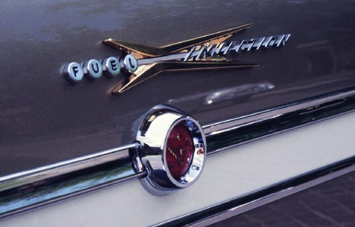
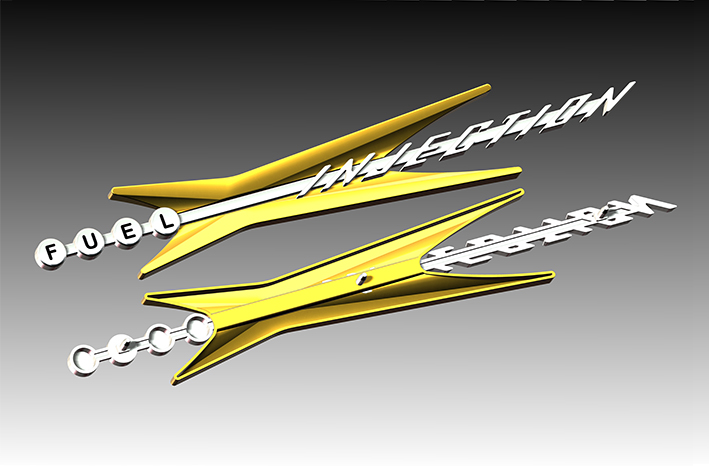
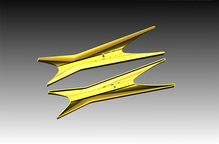
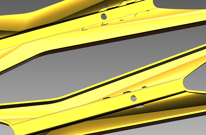
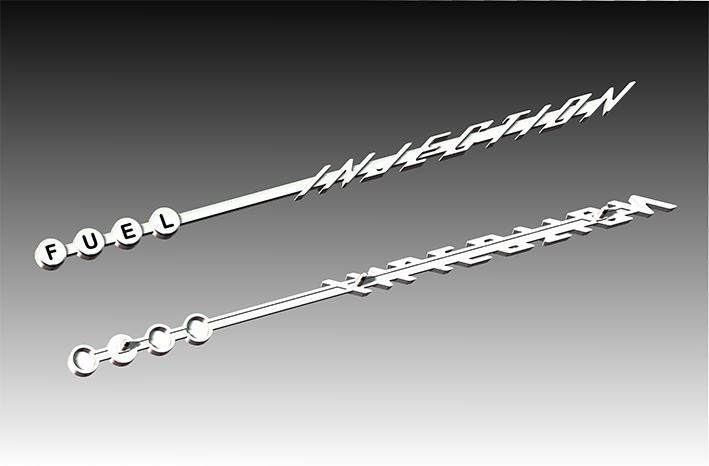
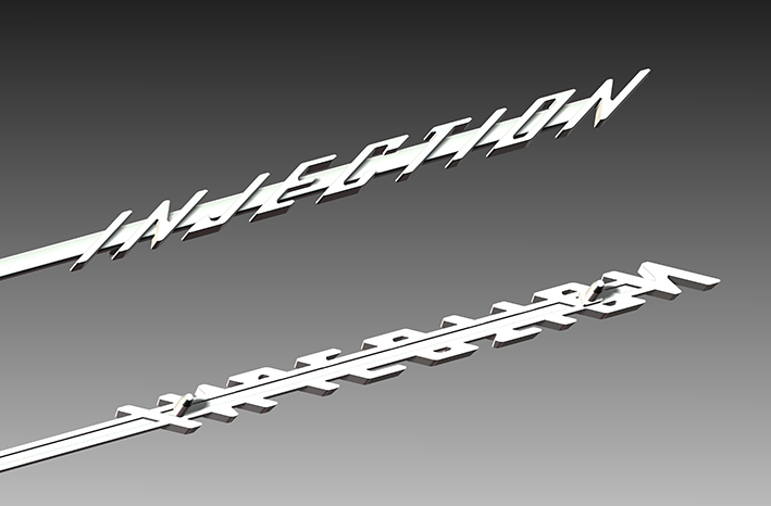
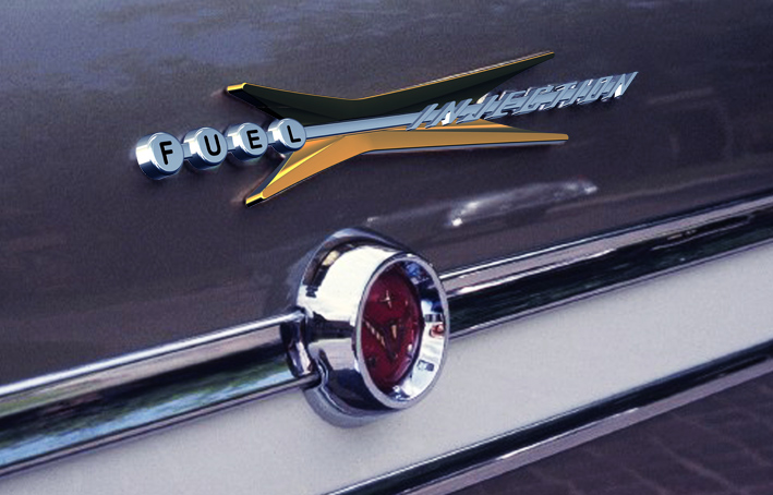
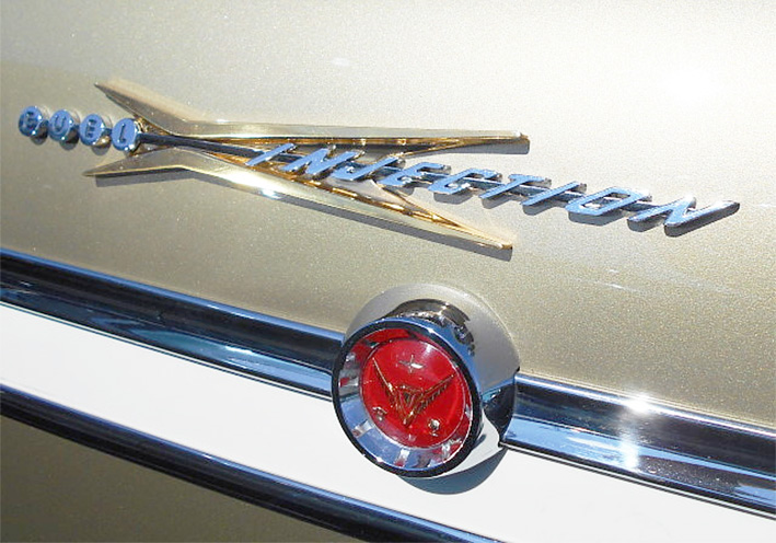
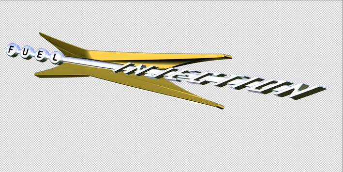
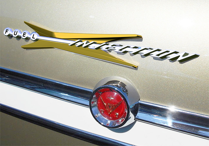
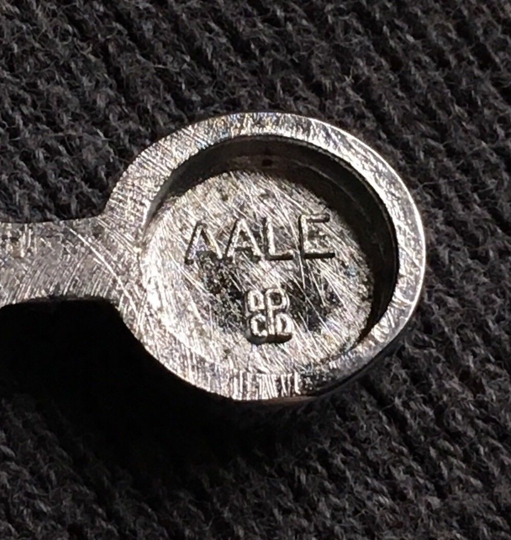
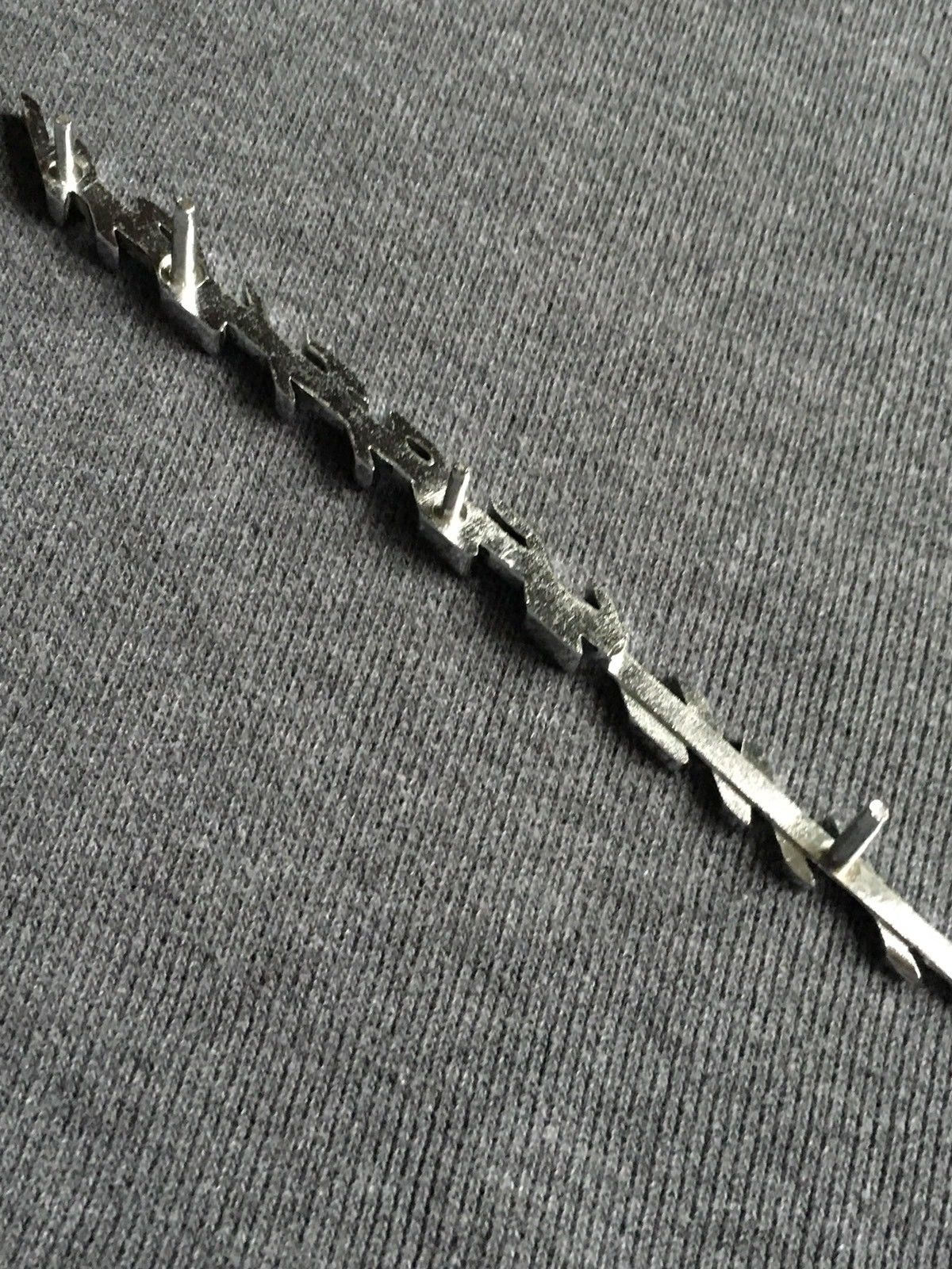
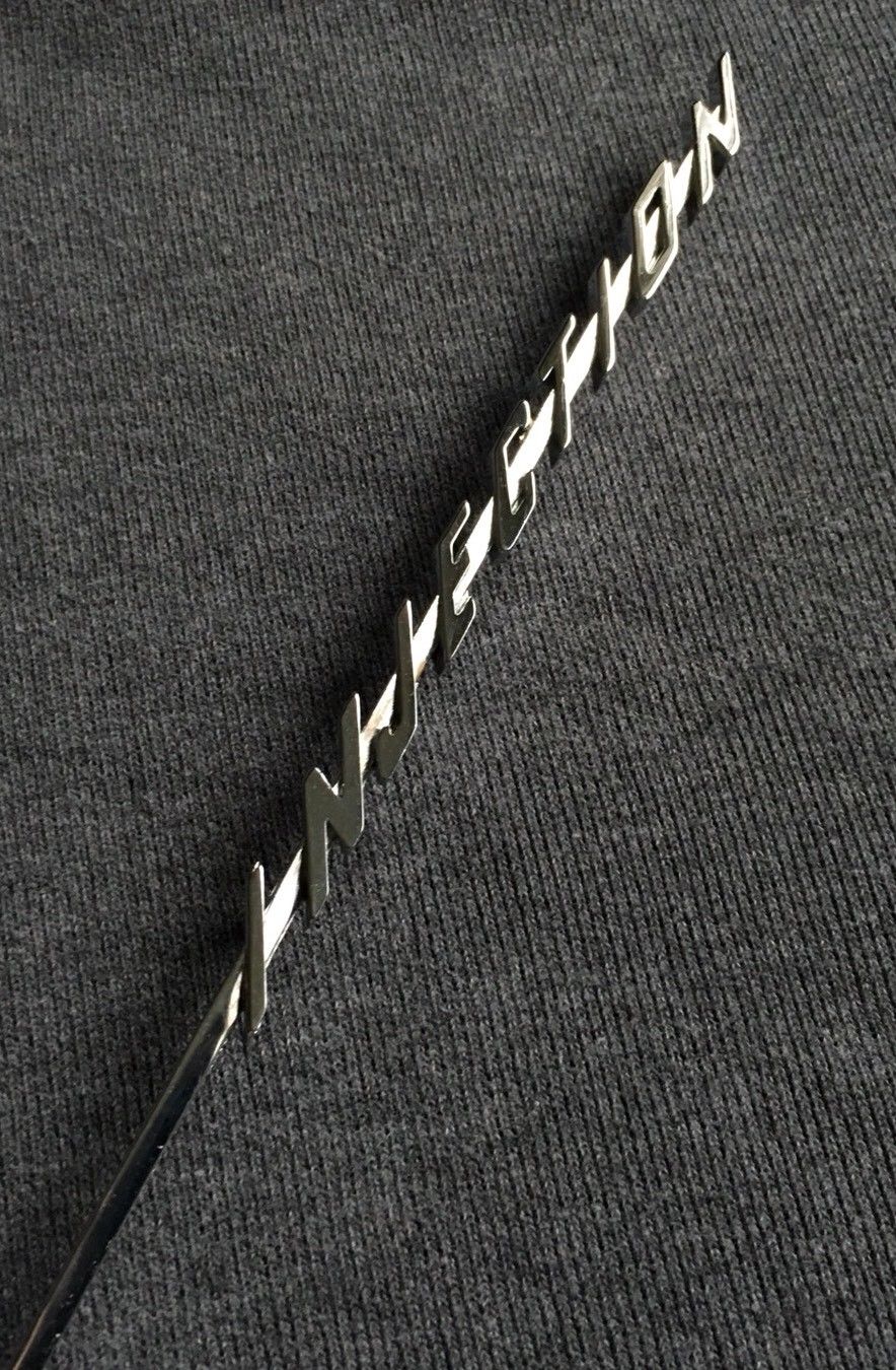
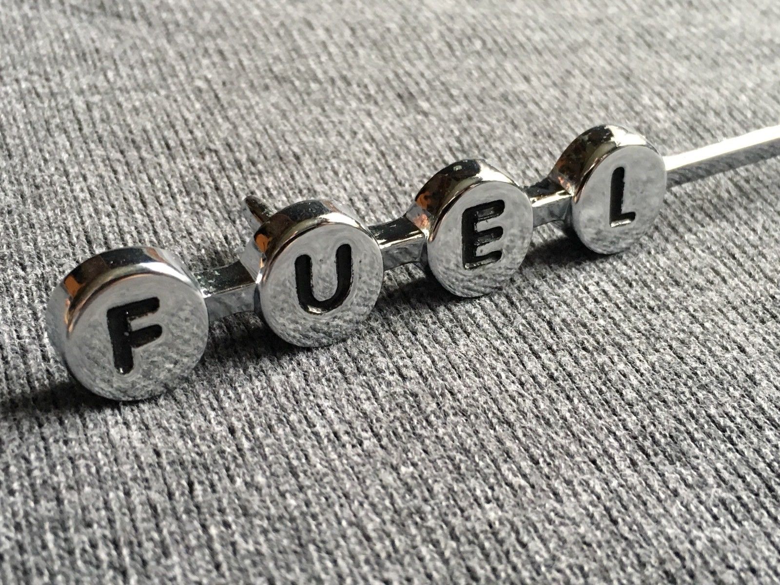
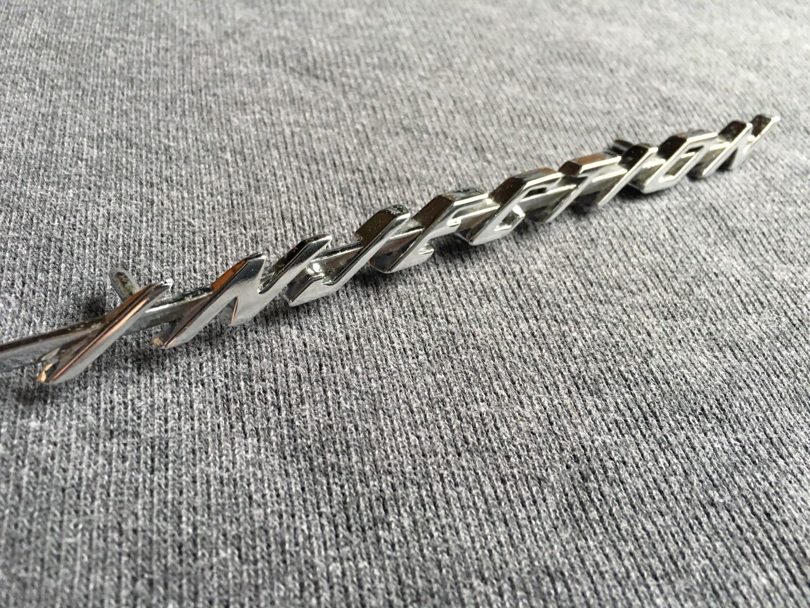
Location: SWITZERLAND | Emblem FUEL Injection 58: A few month ago there was a thread about this, obviously very loved emblem, and very rare. Repros have been in discussion and attempts of modeling presented. As enthusiast of emblems then I modeled this part on the base of pictures, as no reference samples are available. Thus, all you see is by view and not accurate. The precice dimensions should be applied to this model, if one day disposable. Now I did some final corrections for present here. The rear of the emblem I have never seen, it is done as I would be the designer. Some details, Front / Rear View, may help as starter for those who will do repros. Anyway, an exceptional emblem, in reality nicer than just in 3D-RealView. Another challenging game! - SERGE - ;)
Edited by sermey 2018-08-03 8:26 AM
 (01 Original Emblem Fuel Injection 58.jpg) (01 Original Emblem Fuel Injection 58.jpg)
 (02 Emblem Fuel Injection 58 CAD.jpg) (02 Emblem Fuel Injection 58 CAD.jpg)
 (03 Body of Emblem.jpg) (03 Body of Emblem.jpg)
 (04 Details of Body.jpg) (04 Details of Body.jpg)
 (05 Insertion of Emblem.jpg) (05 Insertion of Emblem.jpg)
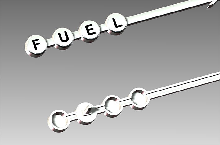 (06 F U E L -Buttons.jpg) (06 F U E L -Buttons.jpg)
 (07 Script I N J E C T I O N.jpg) (07 Script I N J E C T I O N.jpg)
 (08 Replaced Emblem Fuel Injection 58.jpg) (08 Replaced Emblem Fuel Injection 58.jpg)
Attachments
----------------
01 Original Emblem Fuel Injection 58.jpg (158KB - 467 downloads)
02 Emblem Fuel Injection 58 CAD.jpg (171KB - 411 downloads)
03 Body of Emblem.jpg (142KB - 428 downloads)
04 Details of Body.jpg (125KB - 424 downloads)
05 Insertion of Emblem.jpg (116KB - 420 downloads)
06 F U E L -Buttons.jpg (127KB - 429 downloads)
07 Script I N J E C T I O N.jpg (121KB - 430 downloads)
08 Replaced Emblem Fuel Injection 58.jpg (163KB - 412 downloads)
|
|
| |
|
Board Moderator & Exner Expert 10K+
Posts: 13049
Location: Southern Sweden - Sturkö island | Wow, that looks very perfect to me - a lot of work and thinking behind it Serge! I really hope that someone will inform you about the dimensions of this super rare emblem. |
|
| |
|
Expert
Posts: 1208
Location: SWITZERLAND | I found another Picture, downloaded from Danny/57burb (09). To get the emblem from CAD in Photoshop without any background: save from SolidWorks as PNG, in Options set “remove background” and the resolution. Then imported in Photoshop: place, resize and distort to fit on the picture (10). With the correct dimensions should look similar to Original. Just the light and surface settings are not optimal (11). To add: the overall shell is set to 1.6mm, as most other FWL-Emblems. - SERGE -
Edited by sermey 2018-08-04 11:07 AM
 (09 Original Emblem Fuel Injection 58.jpg) (09 Original Emblem Fuel Injection 58.jpg)
 (10 Emblem CAD PrtScreen Distorted.jpg) (10 Emblem CAD PrtScreen Distorted.jpg)
 (11 Replaced EmblemFuel Injection 58.jpg) (11 Replaced EmblemFuel Injection 58.jpg)
Attachments
----------------
09 Original Emblem Fuel Injection 58.jpg (161KB - 433 downloads)
10 Emblem CAD PrtScreen Distorted.jpg (137KB - 417 downloads)
11 Replaced EmblemFuel Injection 58.jpg (162KB - 427 downloads)
|
|
| |
|
Member
Posts: 7
Location: Nashua NH | Cool! you have some computer chops. whats your plan are you going to have it machined?
|
|
| |
|
Expert
Posts: 1208
Location: SWITZERLAND | Hi Vince! I see you first time here - welcome on board of creative and multi-talented people. For the moment I do nothing with - it's just for fun. If the time has come (to have produced in 3D-Printing in High-Resolution for a shiny surface), I will realise some prototypes. For commercial or business purpose there are many good guys here who would care for. The basics are accurate 1 : 1 models in 3D-CAD as shown here. Now some try to go their own way - still waiting and looking forward to results to come. - Computer: 2 DELL Precision M6800 i7-4930 MX and two HD DELL Monitors 27" (2x 30" resp). Much less than a FWL-Car! Then no rust and dirty hands. The applied slogan: Not talk, but simply do-it and enjoy! - SERGE -
Edited by sermey 2018-08-07 3:36 PM
|
|
| |
|
Elite Veteran
Posts: 1159
Location: D-70199 Heslach | sermey - 2018-08-07 8:34 PM
........board of creative and multi-talented people
yes, thats right! |
|
| |
|
Expert 5K+
Posts: 6500
Location: Newark, Texas (Fort Worth) | More pics for you:
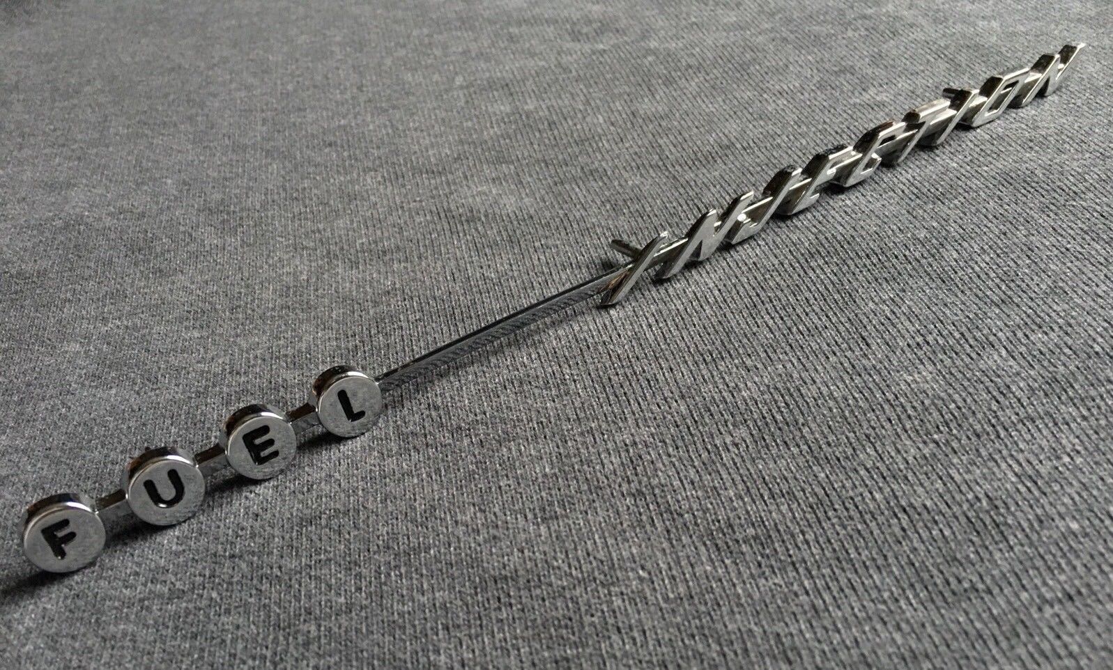 (fuel injectionemblem1.jpg) (fuel injectionemblem1.jpg)
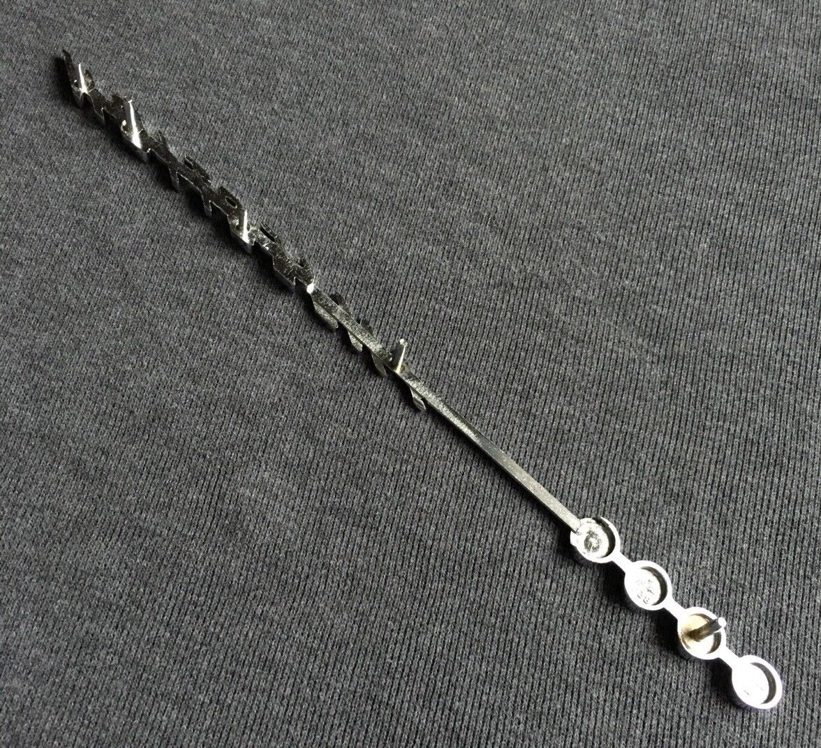 (fuel injectionemblem2.jpg) (fuel injectionemblem2.jpg)
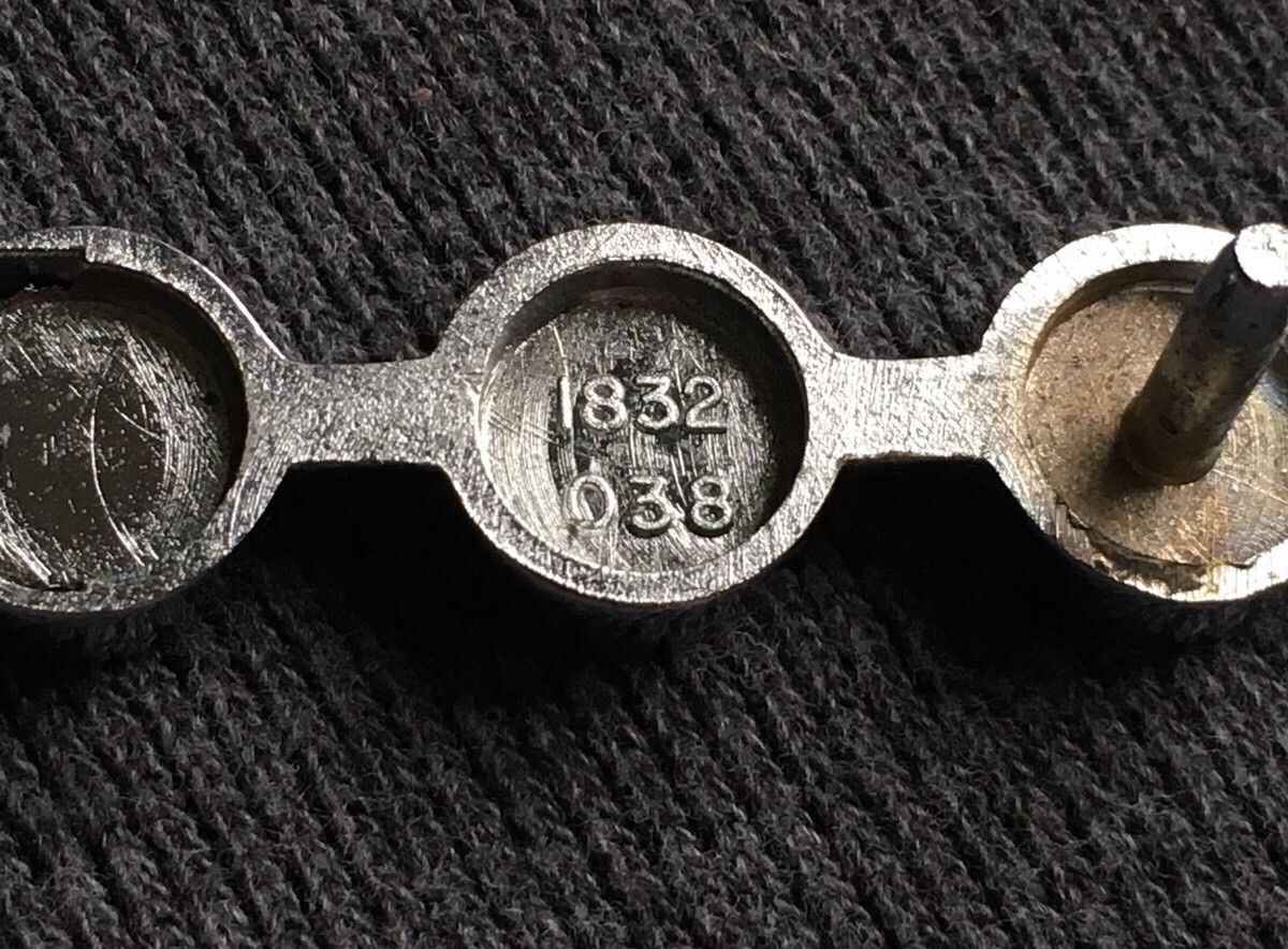 (fuel injectionemblem3.jpg) (fuel injectionemblem3.jpg)
 (fuel injectionemblem4.jpg) (fuel injectionemblem4.jpg)
 (fuel injectionemblem5.jpg) (fuel injectionemblem5.jpg)
 (fuel injectionemblem6.jpg) (fuel injectionemblem6.jpg)
 (fuel injectionemblem7.jpg) (fuel injectionemblem7.jpg)
 (fuel injectionemblem8.jpg) (fuel injectionemblem8.jpg)
Attachments
----------------
fuel injectionemblem1.jpg (385KB - 409 downloads)
fuel injectionemblem2.jpg (396KB - 403 downloads)
fuel injectionemblem3.jpg (221KB - 420 downloads)
fuel injectionemblem4.jpg (169KB - 405 downloads)
fuel injectionemblem5.jpg (449KB - 402 downloads)
fuel injectionemblem6.jpg (288KB - 408 downloads)
fuel injectionemblem7.jpg (402KB - 416 downloads)
fuel injectionemblem8.jpg (474KB - 416 downloads)
|
|
| |
|
Expert
Posts: 1208
Location: SWITZERLAND | mstrug - 2018-09-01 6:30 PM More pics for you: Thank you Marc for these clear pictures. I see many items to be corrected, dimensions still missing. Should model with emblem in hand as shown in the next thread. Your constructive comments, Marc, are always very appreciated. - SERGE - |
|
| |
|
Expert
Posts: 1208
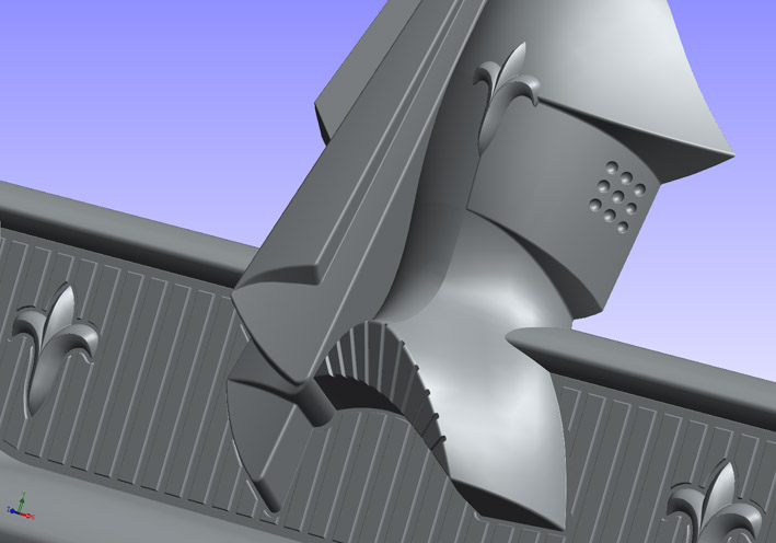
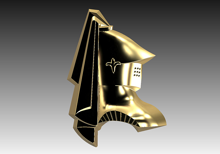
Location: SWITZERLAND | Knight DODGE 59: The 1959 Dodges have their own Knight style. They vary somewhat on the various emblems, due to different supplier at that time. After a few years I started a new attempt to model the 1959 Dodge Knight, based on the rear / side emblem found on most models. This one will then be integrated on all modeled emblems to come. And now finally here it is (01)(02)! A crazy exercise: 3D-Splines, 3D-Curved Surfaces, more a graphical than a geometrical modeling, realized mostly accurate. Overall thickness as original 1.6mm. here some details at no chrome for better view (03)(04)(05)(06). One day the Golden Knight meets the Chrome Knight (07), later on at a Private Party (08). - SERGE - :laugh:
Edited by sermey 2018-09-27 7:21 AM
 (01 Knight Emblem Front View.jpg) (01 Knight Emblem Front View.jpg)
 (02 Knight Emblem Rear View.jpg) (02 Knight Emblem Rear View.jpg)
 (03 Knight Emblem Details.jpg) (03 Knight Emblem Details.jpg)
 (04 Knight Emblem Details.jpg) (04 Knight Emblem Details.jpg)
 (05 Knight Emblem Details.jpg) (05 Knight Emblem Details.jpg)
 (06 Knight Emblem Details.jpg) (06 Knight Emblem Details.jpg)
 (07 Dual Knights Golden - Chrome.jpg) (07 Dual Knights Golden - Chrome.jpg)
 (08 Knights at Private Party.jpg) (08 Knights at Private Party.jpg)
Attachments
----------------
01 Knight Emblem Front View.jpg (133KB - 394 downloads)
02 Knight Emblem Rear View.jpg (119KB - 397 downloads)
03 Knight Emblem Details.jpg (87KB - 381 downloads)
04 Knight Emblem Details.jpg (79KB - 399 downloads)
05 Knight Emblem Details.jpg (95KB - 412 downloads)
06 Knight Emblem Details.jpg (85KB - 399 downloads)
07 Dual Knights Golden - Chrome.jpg (150KB - 403 downloads)
08 Knights at Private Party.jpg (133KB - 407 downloads)
|
|
| |
|
Board Moderator & Exner Expert 10K+
Posts: 13049
Location: Southern Sweden - Sturkö island | I had the privilege to follow the progress of the different steps of this project and the final result is absolutely stunning in accordance with the original in shape and detail. Yet a very difficult 3D Project realized by a true master. |
|
| |
|
Expert 5K+
Posts: 6500
Location: Newark, Texas (Fort Worth) | sermey - 2018-09-27 5:18 AM
mstrug - 2018-09-01 6:30 PM More pics for you: Thank you Marc for these clear pictures. I see many items to be corrected, dimensions still missing. Should model with emblem in hand as shown in the next thread. Your constructive comments, Marc, are always very appreciated. - SERGE -
I can't wait for these to be duplicated. They make a 'bronze' and white 'metal' print media. The 'X' is next? |
|
| |
|
Expert
Posts: 1208
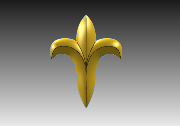
Location: SWITZERLAND | Flower Emblem: This is part of the Rear Emblem, for all here working with older SolidWorks or any CAD Software: Open in SolidWorks (2013 up) the .SLDPRT-File, or import in any SolidWorks or CAD-Software the Parasolid-File .X_T, both as attachment. For animation additional an eDrawing-File .ERPT. Some pictures to look at, all done with this file in SW2013 (Original in SW2016). Pic 05 shows the simple creation of this Emblem (the guides and the planes/intersections): 1. Left Lower Loft, 2. Left Upper Loft, 3. Left Center Loft 4. mirror all for the right half. As I said, just a game! - SERGE -
Edited by sermey 2018-09-28 1:50 PM
 (01 Flower Emblem Flat.jpg) (01 Flower Emblem Flat.jpg)
 (02 Flower Emblem RealView.jpg) (02 Flower Emblem RealView.jpg)
 (03 Flower Emblem Dimetric.jpg) (03 Flower Emblem Dimetric.jpg)
 (04 Flower Emblem Contours.jpg) (04 Flower Emblem Contours.jpg)
 (05 Flower Emblem Lofts.jpg) (05 Flower Emblem Lofts.jpg)
Attachments
----------------
01 Flower Emblem Flat.jpg (108KB - 408 downloads)
02 Flower Emblem RealView.jpg (117KB - 413 downloads)
03 Flower Emblem Dimetric.jpg (121KB - 416 downloads)
04 Flower Emblem Contours.jpg (112KB - 399 downloads)
05 Flower Emblem Lofts.jpg (144KB - 412 downloads)
06 SW2013 Flower Emblem.SLDPRT (278KB - 388 downloads)
07 Flower Emblem Parasolid.x_t (89KB - 400 downloads)
08 SW2013 Flower Emblem.EPRT (54KB - 383 downloads)
|
|
| |
|
Expert
Posts: 1208
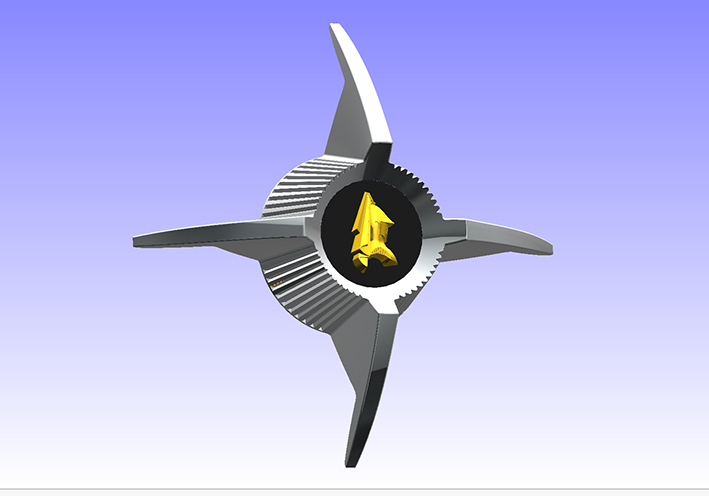
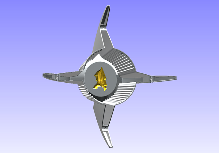
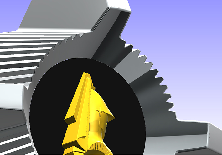
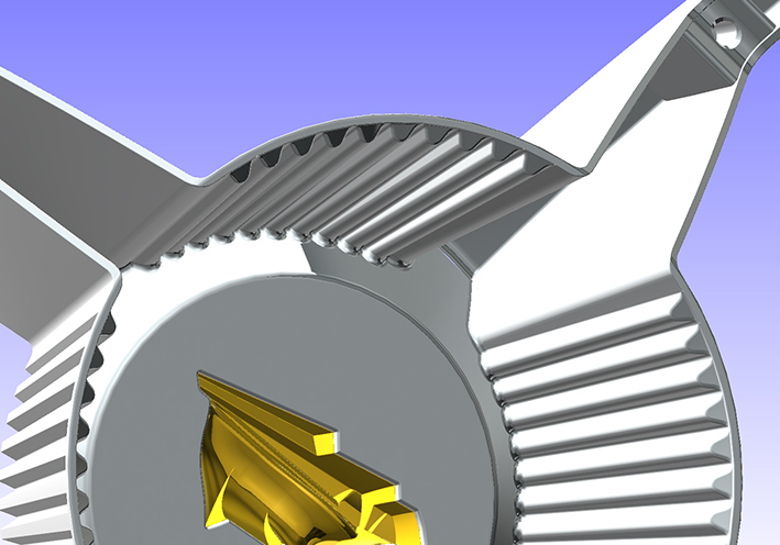
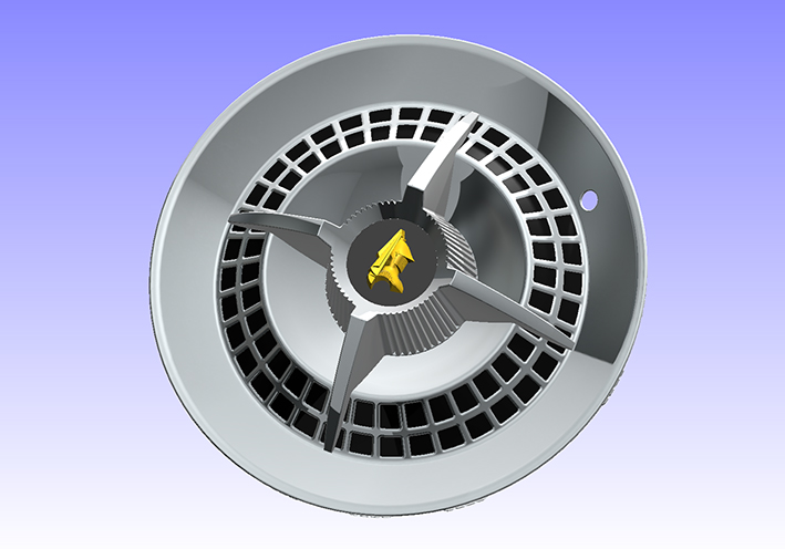
Location: SWITZERLAND | Spinner DODGE 59: In addition to the first thread presenting the HubCap, now with the disposable Knight Emblem I can show the modeled Spinner, in Black and Golden (01). The rear side is done as well as the Original (02). In the partly zoomed view details become better visible (03) (04). Finally the assembled HubCap (05). As this is a ForwardLook part, the Knight has to look forward, to fit on left and right side of the car . Thus, all emblems to come will be as well for left and right side, and so the produced parts in 3D-Printing when ready. - SERGE - :) N.B.: In Front View the Assemled HubCaps appears somewhat different than used to be. This, because in CAD the Spinner is not reflected on the HubCap.
Edited by sermey 2018-10-03 9:27 AM
 (01 Spinner Front View.jpg) (01 Spinner Front View.jpg)
 (02 Spinner Rear View.jpg) (02 Spinner Rear View.jpg)
 (03 Spinner Details1.jpg) (03 Spinner Details1.jpg)
 (04 Spinner Details2.jpg) (04 Spinner Details2.jpg)
 (05 HubCap Assembled.jpg) (05 HubCap Assembled.jpg)
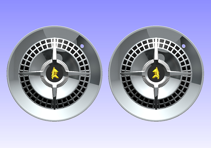 (06 Dual Mirrored Knight.jpg) (06 Dual Mirrored Knight.jpg)
Attachments
----------------
01 Spinner Front View.jpg (125KB - 392 downloads)
02 Spinner Rear View.jpg (123KB - 402 downloads)
03 Spinner Details1.jpg (155KB - 400 downloads)
04 Spinner Details2.jpg (146KB - 410 downloads)
05 HubCap Assembled.jpg (172KB - 399 downloads)
06 Dual Mirrored Knight.jpg (196KB - 401 downloads)
|
|
| |
|
Elite Veteran,, James Passed away March 2021, He will be Missed
Posts: 1028
Location: Melbourne, Australia | Simply amazing ! |
|
| |
|
Board Moderator & Exner Expert 10K+
Posts: 13049
Location: Southern Sweden - Sturkö island | You never stop surprising us with one fantastic 3-D design after Another Serge!
It would be a very cool thing to make the Knights mirrored for the left and right side - many would never notice, but a connoisseur would stop dead in his tracks and drool….. |
|
| |
|
Expert
Posts: 1208
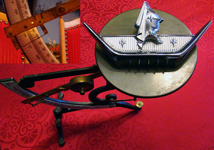
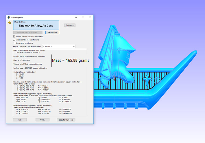
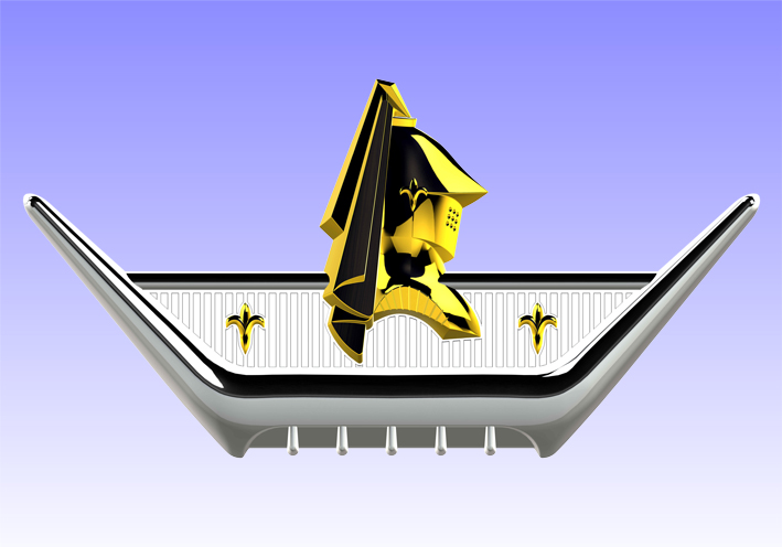
Location: SWITZERLAND | Rear Emblem (Deck Lid Ornament or Medaillon): This rear emblem is found as well on 1959 Coronets, here presented as model in the original color combination, in White (01). The Rear Views in flat mode for better visibility of the details (02) (03) (04). Here the Front View in Wire Frame for “play” on Photoshop (05). On an antique scale the original emblem shows a weight of 150g (06), in comparison to the model, material Zinc AS Cast, 165g (07). The difference is due to the constant overall thickness of 1.6mm , illustrated in section views of the model (08), whereas the original emblem is partly thinner. When golden plated the original white emblem looks more precious (09). My preferred color combs as on my (white) convertible is Gold-Red (10). The 1959 DODGE Coronet has two identical emblems, one on the left fender and one on the right fender, thus one knight looks backward. Here the two emblems for both forward-looking knights (11). Not a rare emblem, but awesome, here perfectly modeled. - SERGE -
 (01 Rear Emblem - Front View Original White.jpg) (01 Rear Emblem - Front View Original White.jpg)
 (02 Rear Emblem - Rear View 1 Flat.jpg) (02 Rear Emblem - Rear View 1 Flat.jpg)
 (03 Rear Emblem - Rear View 2 Flat.jpg) (03 Rear Emblem - Rear View 2 Flat.jpg)
 (04 Rear Emblem - Rear View 3 Flat.jpg) (04 Rear Emblem - Rear View 3 Flat.jpg)
 (05 Rear Emblem - Front View in Wire Frame.jpg) (05 Rear Emblem - Front View in Wire Frame.jpg)
 (06 Original Rear Emblem - on Antique Scale 150g.jpg) (06 Original Rear Emblem - on Antique Scale 150g.jpg)
 (07 Rear Emblem - Model in Zinc As Cast 165g.jpg) (07 Rear Emblem - Model in Zinc As Cast 165g.jpg)
 (08 Rear Emblem - Section Views 1.6mm.jpg) (08 Rear Emblem - Section Views 1.6mm.jpg)
 (09 Rear Emblem - Front View Gold-White.jpg) (09 Rear Emblem - Front View Gold-White.jpg)
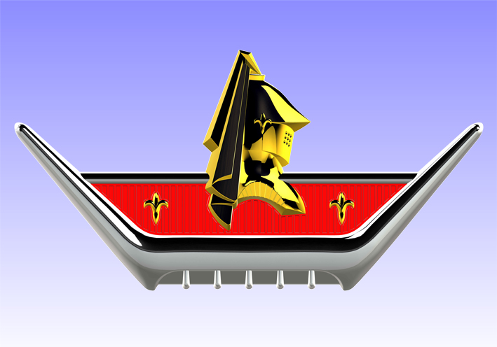 (10 Rear Emblem - Front View Gold-Red.jpg) (10 Rear Emblem - Front View Gold-Red.jpg)
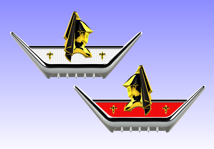 (11 Dual Emblems - Forward-Looking Knights.jpg) (11 Dual Emblems - Forward-Looking Knights.jpg)
Attachments
----------------
01 Rear Emblem - Front View Original White.jpg (149KB - 367 downloads)
02 Rear Emblem - Rear View 1 Flat.jpg (124KB - 353 downloads)
03 Rear Emblem - Rear View 2 Flat.jpg (128KB - 353 downloads)
04 Rear Emblem - Rear View 3 Flat.jpg (124KB - 361 downloads)
05 Rear Emblem - Front View in Wire Frame.jpg (152KB - 368 downloads)
06 Original Rear Emblem - on Antique Scale 150g.jpg (169KB - 364 downloads)
07 Rear Emblem - Model in Zinc As Cast 165g.jpg (123KB - 375 downloads)
08 Rear Emblem - Section Views 1.6mm.jpg (121KB - 365 downloads)
09 Rear Emblem - Front View Gold-White.jpg (165KB - 377 downloads)
10 Rear Emblem - Front View Gold-Red.jpg (180KB - 362 downloads)
11 Dual Emblems - Forward-Looking Knights.jpg (181KB - 355 downloads)
|
|
| |
|

Expert
Posts: 1443
Location: Oconomowoc Wi | <p>The work is fascinating, but to what end? Does this mean the ability to reproduce parts in 3D, or what? I'm Jonesing watching all this work on the '59 Dodge</p>
Edited by Bart_59_Dodge 2019-01-06 5:20 PM
|
|
| |
|
Location: Parts Unknown | Serge -
I own a good condition example of the gold "star" piece of the Fuel Injection emblem.
If I measure for you ? Send piece to you ? Will this enable you to complete the
template building work ?
|
|
| |
|
Expert
Posts: 1208
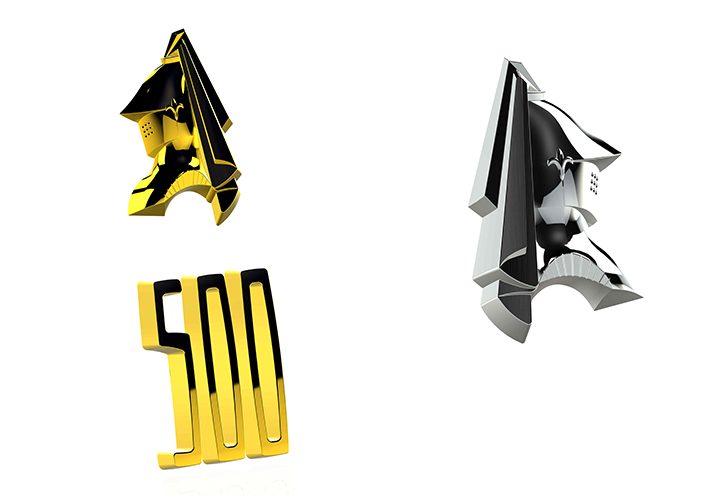
Location: SWITZERLAND | Doctor DeSoto - 2019-01-07 1:32 AM Serge - I own a good condition example of the gold "star" piece of the Fuel Injection emblem. If I measure for you ? Send piece to you ? Will this enable you to complete the template building work ? Thank you for your offer (first!!!). For a real and original-correct model I need to check, when done, all corners 3D from edge to edge, and then correct the dimensions I initialy measured. Our eyes are very critical when comparing copy and original. Thus I will only start when I have the emblem in hand. Now I purchased and wait for the 1962 Chrysler New Yorker / Newport Grill Emblem, as I like it, just for modeling. And I do only when I am in the mood for do it. On pictures I met various Fuel Injection Emblems, the letters are somewhat different. Your example must not be nice, important the original one. Contact me on sermey at bluewin dot ch. Here I started the 1959 D500 Emblem: copy - move - mirror - resize the existing knight to the right position, model the numbers 500 as well in the right position (01). Later comes the body and the final details. - SERGE -
Edited by sermey 2019-01-08 7:08 AM
 (1959 D500 Emblem Test.jpg) (1959 D500 Emblem Test.jpg)
Attachments
----------------
1959 D500 Emblem Test.jpg (114KB - 352 downloads)
|
|
| |
|
Expert
Posts: 1208
Location: SWITZERLAND | Bart_59_Dodge - 2019-01-06 11:19 PM The work is fascinating, but to what end? Does this mean the ability to reproduce parts in 3D, or what? I'm Jonesing watching all this work on the '59 Dodge Good Question Bart. As you stated, the 3D models offer the ability to reproduce these parts in original and even in better quality. Can be used for direct injection tooling by electro-erosion technology, for build prototypes by stereolithography, or done in 3D-Printing. All all items in 1 : 1 real size, without any dimension, just by a STEP-, STL- or Parasolid-File. As emblems are mostly rechromed, the surfaces of the new 3D-Print Technology are still not sufficient, or the fine edges may be removed by polishing. Only bigger parts, as the Rear Antenna Socket, would show very nice results. Best is producing, as original done, using an injection tool. The initial costs are quite high. At low quantities the part becomes too expensive. I did already some preliminary tests, but still not sufficient in quality for rechromed parts. Here a Push-Button, 3D-Printed with green filament (01), 3D-Equipment USD1000. Will present here samples as soon they become usable and affordable. The technology develops. For now, the existing models keep the quality all the time, can say a “long lasting conservation” of impressive designs. - SERGE -
Edited by sermey 2019-01-12 5:53 AM
 (01 3D-Printed Push Button Illuminated.jpg) (01 3D-Printed Push Button Illuminated.jpg)
Attachments
----------------
01 3D-Printed Push Button Illuminated.jpg (94KB - 358 downloads)
|
|
| |
|
Expert
Posts: 1208
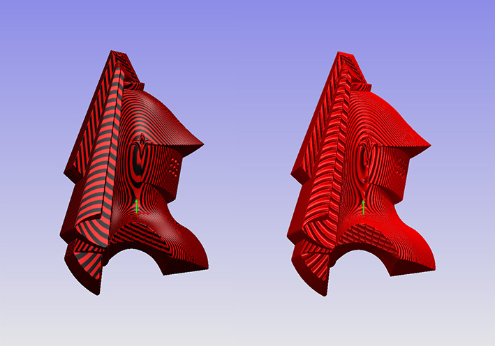
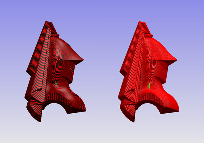
Location: SWITZERLAND | 3D-Print Analysis: Depending of the layer height, the slices become more or less visible. The bigger the part, the roughness of the surface appear smoother. This is shown here by a 3D-Printing analysis, on a Knight of the rear emblem, and on the socket of a rear antenna, both 1 : 1, original scale. Applied layer height 0.2mm, 0.1mm and 0.05mm. The left side of the pictures show the resulting striaton lines, the right side the simulated surface as bump map. To smooth the surfaces, they can be fine sandblasted, then galvanic coppered, polished and final rechromed. Looking forward what will be the the reality . . . . - SERGE -
 (01 Knight 3D-Printing.jpg) (01 Knight 3D-Printing.jpg)
 (02 Knight Layer Height 0.2mm.jpg) (02 Knight Layer Height 0.2mm.jpg)
 (03 Knight Layer Height 0.1mm.jpg) (03 Knight Layer Height 0.1mm.jpg)
 (04 Knight Layer Height 0.05mm.jpg) (04 Knight Layer Height 0.05mm.jpg)
 (05 Antenna Socket 3D-Printing.jpg) (05 Antenna Socket 3D-Printing.jpg)
 (06 Antenna Socket Layer Height 0.2mm.jpg) (06 Antenna Socket Layer Height 0.2mm.jpg)
 (07 Antenna Socket Layer Height 0.1mm.jpg) (07 Antenna Socket Layer Height 0.1mm.jpg)
 (08 Antenna Socket Layer Height 0.05mm.jpg) (08 Antenna Socket Layer Height 0.05mm.jpg)
Attachments
----------------
01 Knight 3D-Printing.jpg (118KB - 348 downloads)
02 Knight Layer Height 0.2mm.jpg (132KB - 348 downloads)
03 Knight Layer Height 0.1mm.jpg (126KB - 342 downloads)
04 Knight Layer Height 0.05mm.jpg (114KB - 346 downloads)
05 Antenna Socket 3D-Printing.jpg (116KB - 346 downloads)
06 Antenna Socket Layer Height 0.2mm.jpg (100KB - 347 downloads)
07 Antenna Socket Layer Height 0.1mm.jpg (101KB - 347 downloads)
08 Antenna Socket Layer Height 0.05mm.jpg (97KB - 352 downloads)
|
|
| |
|
Regular
Posts: 57
Location: Switzerland | Hi I am Dani from Zurich, and will most probably purchase a 1959 CRL D 500 next spring.
Just what I was looking for that Chevron Emblem. Could these be reproduced, so I could install that on the car ?
They can be nowhere found as originals!
Super great work. So in future all emblems could be reproduced
Dani - keep on going ! |
|
| |
|
Expert
Posts: 1208
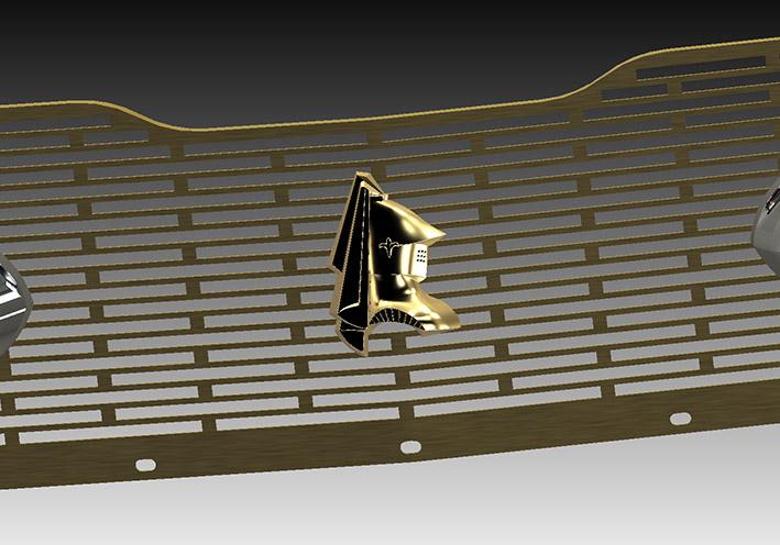
Location: SWITZERLAND | First 3D-Prints: Now the time is near for 3D-Prints at affordable costs and at a quality up to 10 micron for a rechromable surface. The first samples with my favorite, the Knight, at original proportions in transparent Resin (01). The rear side shows the mounting studs for M4 bolts. Then I resized the Knight, not proportional to give a wider aspect, and to fit the front curvature of the DODGE (02). Same resized Knight, just removed the Grille (03). The studs are designed to fit on the grill without any modifications and to be aligned (04). This is the initial 3D-Print of the resized Knight (05). The first check on the car gives a first impression (06). Of course, the Knight will be chrome and/or golden plated. For the CAD-Versions here I used satin gold. Satin Gold can as well be sprayed on the Knight for a low cost handling.
Most modeled parts presented here now can be produced by 3D-Printing at highest precision and at reasonable costs. - SERGE - ;)
Edited by sermey 2020-02-16 4:02 PM
 (01 3D-Printed Knight Original.jpg) (01 3D-Printed Knight Original.jpg)
 (02 Resized Knight on Grille CAD.jpg) (02 Resized Knight on Grille CAD.jpg)
 (03 Resized Knight - Grille Removed CAD.jpg) (03 Resized Knight - Grille Removed CAD.jpg)
 (04 Rear Mounting Studs CAD.jpg) (04 Rear Mounting Studs CAD.jpg)
 (05 3D-Printed Knight Resized Front-Rear View.jpg) (05 3D-Printed Knight Resized Front-Rear View.jpg)
 (06 First Check on Car.jpg) (06 First Check on Car.jpg)
Attachments
----------------
01 3D-Printed Knight Original.jpg (195KB - 273 downloads)
02 Resized Knight on Grille CAD.jpg (120KB - 277 downloads)
03 Resized Knight - Grille Removed CAD.jpg (77KB - 282 downloads)
04 Rear Mounting Studs CAD.jpg (162KB - 280 downloads)
05 3D-Printed Knight Resized Front-Rear View.jpg (155KB - 282 downloads)
06 First Check on Car.jpg (195KB - 275 downloads)
|
|
| |
|
Expert 5K+
Posts: 9904
Location: Lower Mainland BC | .
Great work Serge!
No, let me change that....
FANTASTIC work Serge!! Congratulations.
|
|
| |
|
Member
Posts: 30
Location: Germany | This is so amazing!
3D printing with resin provides incredible details.
Serge, please show the results when you will have finished it with a suiting surface.
I think that no one will ever notice that this part was printed. At least from a usual viewing distance.
I am pretty sure someone already said it, but THIS is one key to the future of our hobby. Imagine not to rely on draining NOS supplies or wrecked cars to keep our cars on the road for the next decades!
Maik |
|
| |
|
Elite Veteran
Posts: 1159
Location: D-70199 Heslach | Serge, great work. Maybe i visit you once to learn a little bit |
|
| |
|
Board Moderator & Exner Expert 10K+
Posts: 13049
Location: Southern Sweden - Sturkö island | Serge strikes again! I know the effort and dedication that has been put into this - the result is stunning!
This is the future for to be able to get rare items reproduced at a fair cost.
Great work as always from the 3D-master! |
|
| |
|
Regular
Posts: 57
Location: Switzerland | A genius at work ! Congrats Serge,
I would be happy to have this Knight also on my grill...
Let me know, if you would sell one ?
Dani |
|
| |
|
Expert 5K+
Posts: 9904
Location: Lower Mainland BC | .
Not sure how you created the 3D model file for the 3D printer. I understand that there are 3D laser scanners that can be used to create a printer file. Have you considered this?
|
|
| |
|
Expert 5K+
Posts: 5006
| 56D500boy - 2020-02-17 3:04 PM . Not sure how you created the 3D model file for the 3D printer. I understand that there are 3D laser scanners that can be used to create a printer file. Have you considered this? :) thats what he did, he scanned the knights head from the rear emblem. then scaled it up. Pretty slick |
|
| |
|
Board Moderator & Exner Expert 10K+
Posts: 13049
Location: Southern Sweden - Sturkö island | Short comment, no scanner |
|
| |
|
Member
Posts: 30
Location: Germany | I experimented with photogrammetry and it is impressing what is already possible, even with freeware. BUT you will not get this quality from a scan.
You can use it to capture the shape and even the dimensions to a good amount, but it always requires manual post processing to get to those smooth surfaces and sharp edges.
IMHO that's the result from a good old caliper, patience and some imagination. |
|
| |
|
Expert
Posts: 1208
Location: SWITZERLAND | Lancer Emblem: This Emblem is modeled throughout in Surface Technology, other than in usual said Solid Technology (01) (01a). By thicken a surface, here by 0.7mm, the surface body becomes a thin solid part. For 3D-Printing it will be filled to a solid body, shown before the electro-plating process (02). The Knight on this emblem is somewhat different then all others on the car, and the flower on the face is missing. Here I used my already modeled Knight, did some upgrade on the flowers edge (03a) (03b). As well the same flower for the panel, renamed to Dual Flower: insert – copy mirror down – resize non uniform, to get as well similar to the Original, then “connect” up / down with the collar (04). There are four basic components to create this emblem: 1. The Lance in satin gold (05 2. The Knight in satin gold (06) 3. The Panel in satin chrome (07) 4. The Dual Flower in satin gold (08) These surface parts positioned, trimmed to each other and getting then 6 parts (09) (10), merge them and the emblem is done. Not forget to deform in order to fit on the fender (11). Finally mirrored to get left and right, all golden anodized and the colors as on my DODGE (12). This Lancer Emblem, another outstanding brandmark of the DODGE 59 Custom Royal Lancer, now ready for 3D-Printing. - SERGE - ;)
Edited by sermey 2020-04-04 12:49 PM
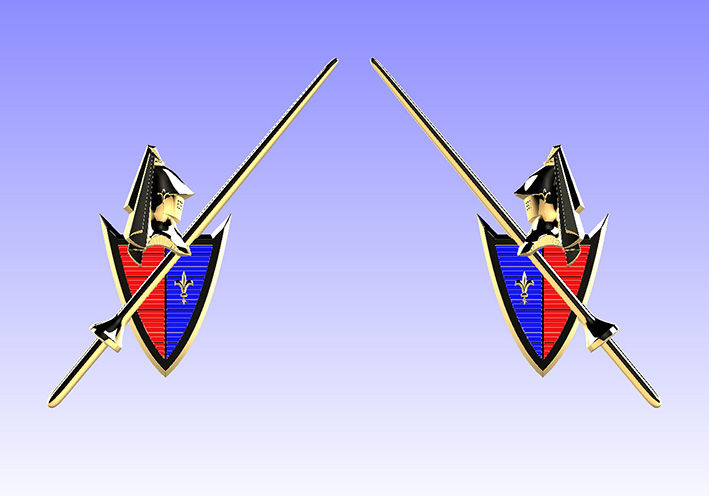 (01 Lancer Emblem Left - Right.jpg) (01 Lancer Emblem Left - Right.jpg)
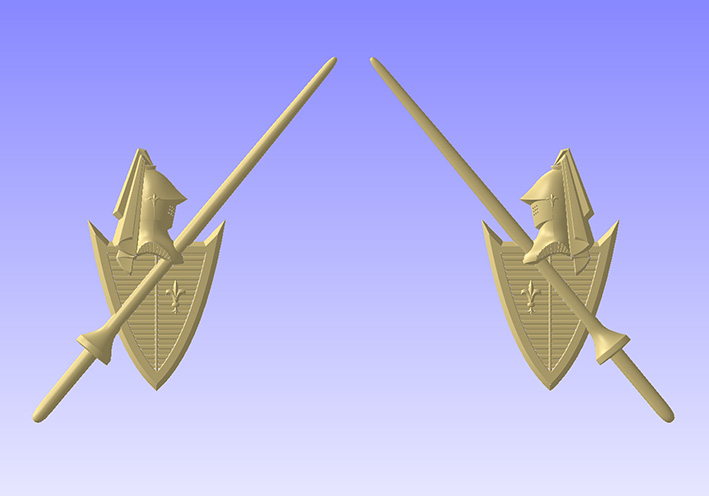 (01a Unmetalized Emblem Left -Right.jpg) (01a Unmetalized Emblem Left -Right.jpg)
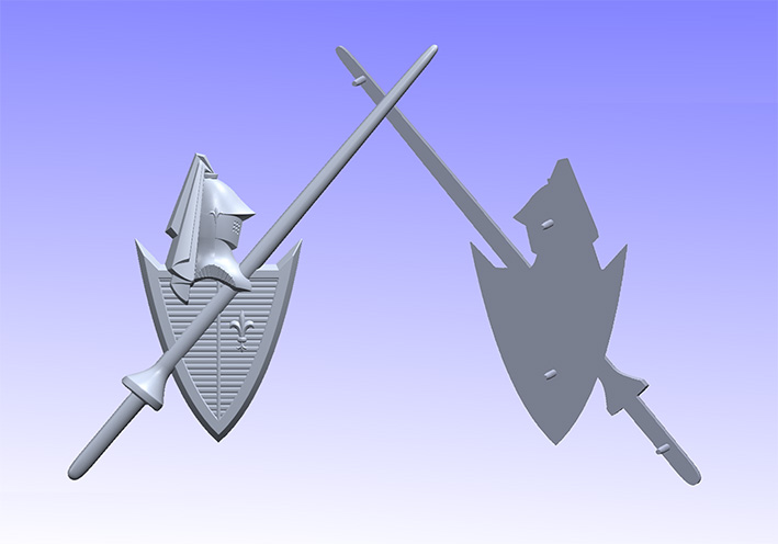 (02 Filled Emblem Front - Rear View.jpg) (02 Filled Emblem Front - Rear View.jpg)
 (03a Earlier Flower.jpg) (03a Earlier Flower.jpg)
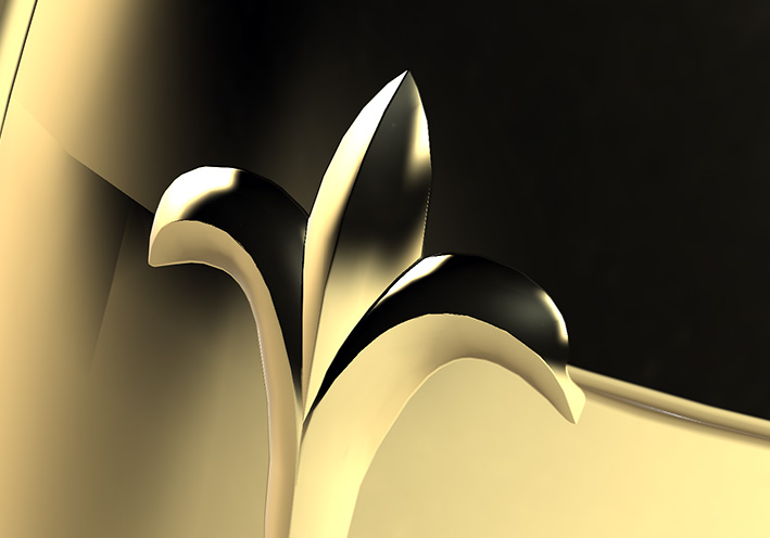 (03b Modified Flower.jpg) (03b Modified Flower.jpg)
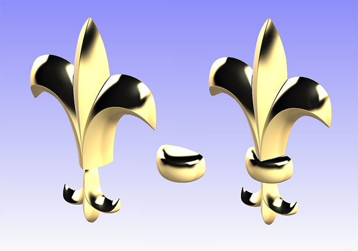 (04 Dual Flower.jpg) (04 Dual Flower.jpg)
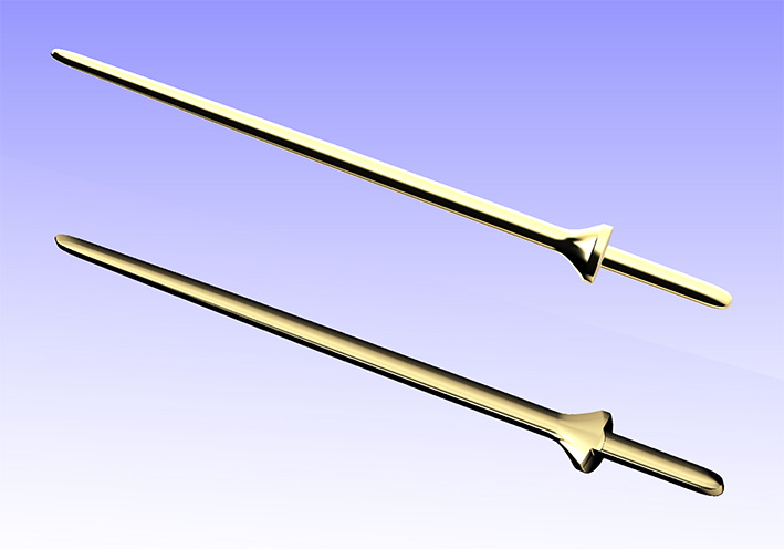 (05 Lance Front - Rear View.jpg) (05 Lance Front - Rear View.jpg)
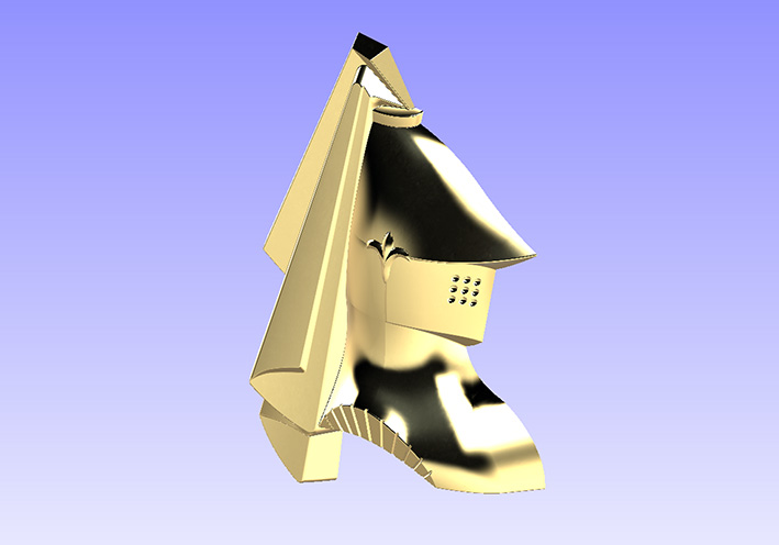 (06 Knight in satin gold.jpg) (06 Knight in satin gold.jpg)
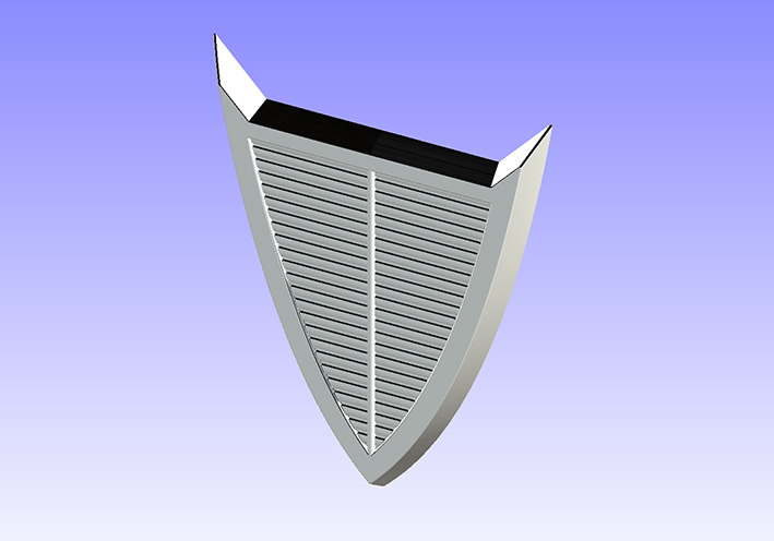 (07 Panel in satin chrome.jpg) (07 Panel in satin chrome.jpg)
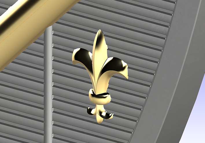 (08 Dual Flower on Panel.jpg) (08 Dual Flower on Panel.jpg)
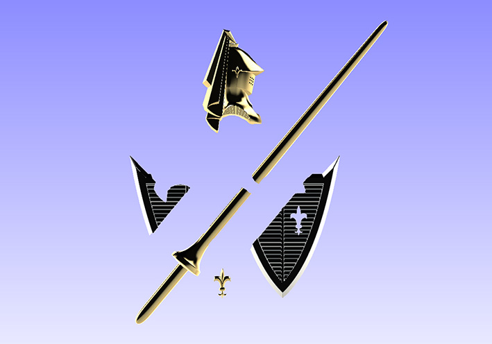 (09 Trimed Parts Exploded View.jpg) (09 Trimed Parts Exploded View.jpg)
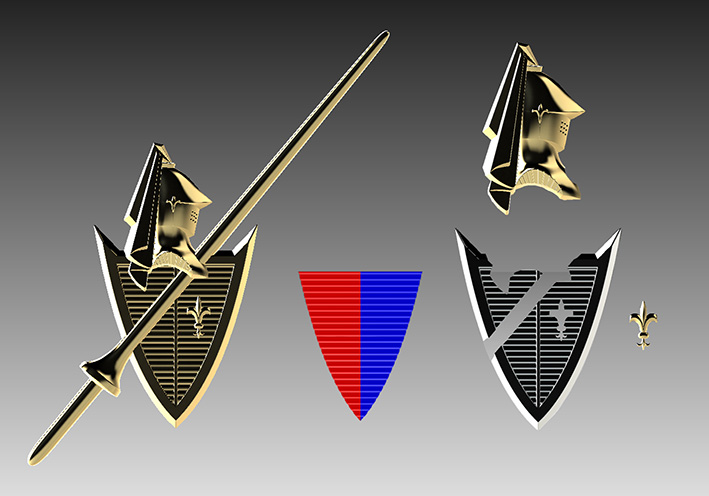 (10 Trimed Parts Flat View.jpg) (10 Trimed Parts Flat View.jpg)
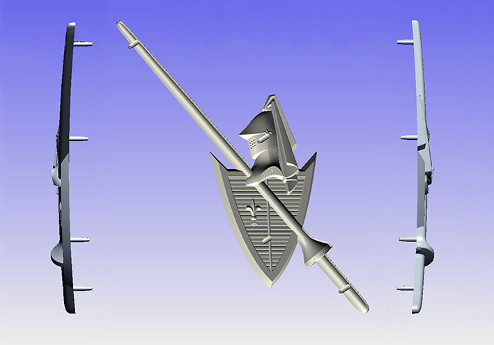 (11 Bent Emblem Side - Rear View.jpg) (11 Bent Emblem Side - Rear View.jpg)
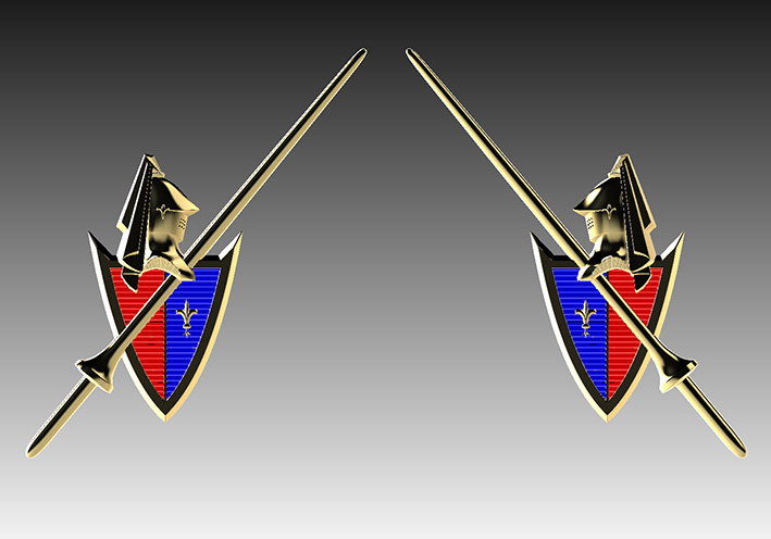 (12 Lancer Emblem Left - Right.jpg) (12 Lancer Emblem Left - Right.jpg)
Attachments
----------------
01 Lancer Emblem Left - Right.jpg (101KB - 241 downloads)
01a Unmetalized Emblem Left -Right.jpg (81KB - 249 downloads)
02 Filled Emblem Front - Rear View.jpg (73KB - 245 downloads)
03a Earlier Flower.jpg (77KB - 251 downloads)
03b Modified Flower.jpg (71KB - 242 downloads)
04 Dual Flower.jpg (90KB - 244 downloads)
05 Lance Front - Rear View.jpg (75KB - 239 downloads)
06 Knight in satin gold.jpg (71KB - 245 downloads)
07 Panel in satin chrome.jpg (76KB - 242 downloads)
08 Dual Flower on Panel.jpg (122KB - 242 downloads)
09 Trimed Parts Exploded View.jpg (77KB - 247 downloads)
10 Trimed Parts Flat View.jpg (105KB - 251 downloads)
11 Bent Emblem Side - Rear View.jpg (82KB - 247 downloads)
12 Lancer Emblem Left - Right.jpg (96KB - 248 downloads)
|
|
| |
|
Board Moderator & Exner Expert 10K+
Posts: 13049
Location: Southern Sweden - Sturkö island | Fantastic work by the master! |
|
| |
|
Expert
Posts: 1208
Location: SWITZERLAND | 1962 Chrysler New Yorker Emblem: Out of the line I present how to model an emblem. As I like the 1962 Chrysler New Yorker Emblem I purchased once a time ago just for modeling, as it is easy to create. This as well to motivate others for doing the same when fascinated. First a sample in hand is needed! Then take a picture exact from front view. In Photoshop (PS) open the picture, set the canvas size according the emblem size: 177 x 64.8mm, and position/scale/rotate it to fit exact in height, width and horizontal with the help of some guide lines (001). Cut-out all around the emblem, create a contour line with the border selection tool (002), and save the two pictures as JPG. In the attachment add .JPG on the names to get the picture in real size, or too big here on screen! These pictures insert in separate sketches (sketch tool, SW2016). Now draw the lines along the parts and dimension to fix them. All this will be the MasterSketch to be used for position and create the 5 parts: Center letter C. Generated by “Swept Boss” to get rounded faces, along 4 contour guide lines and 3 intersections (start-mid-end). Only one quarter is needed, the others are mirrored horizontal and vertical. Then cut-out to get a “C” from the “O” (03). Upper Ornament. Use as well the contour, the borders are all done by sweeping to avoid any flat face. Left side done, the right side simply bay mirror (04). Lower Ornament. All similar to the upper ornament (05). Center Bar. All again, but swept in one and then cut-out in the center (06). Rear Black Base. Extrude the base contour in the original thickness (07). The Final Emblem. Apply some fillets where needed according the sample, check all dimensions (point to point with the measurement tool) and modify them to be correct. Now the 1962 Chrysler New Yorker Emblem is ready. Merged all parts to a single Solid Body it can be used for 3D-Printing! Good Luck - SERGE -
Edited by sermey 2020-04-06 6:26 AM
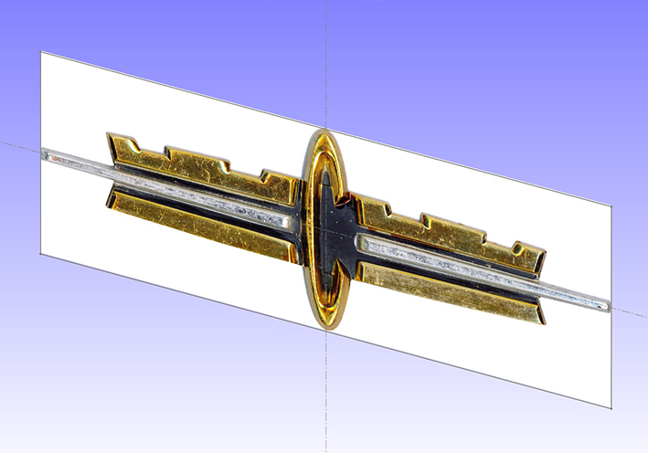 (01 Picture PS inserted.jpg) (01 Picture PS inserted.jpg)
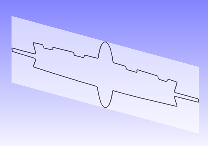 (02 Contour PS inserted.jpg) (02 Contour PS inserted.jpg)
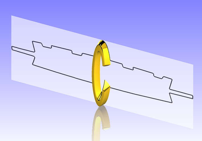 (03 Center Letter C modeled.jpg) (03 Center Letter C modeled.jpg)
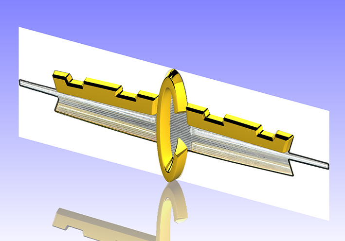 (04 Upper Ornament modeled.jpg) (04 Upper Ornament modeled.jpg)
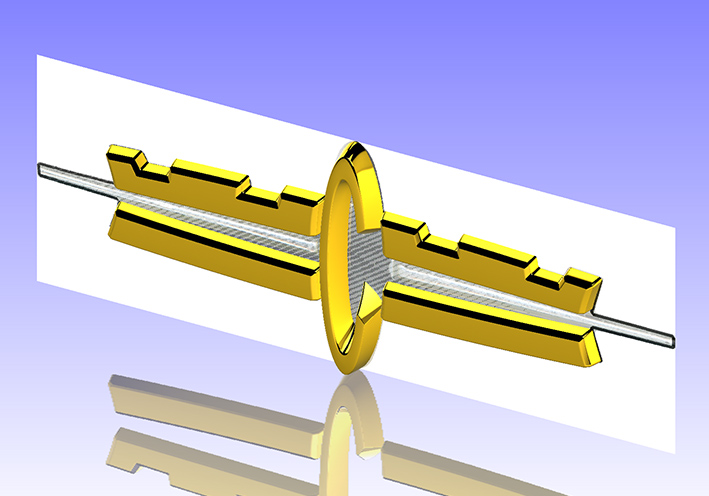 (05 Lower Ornament modeled.jpg) (05 Lower Ornament modeled.jpg)
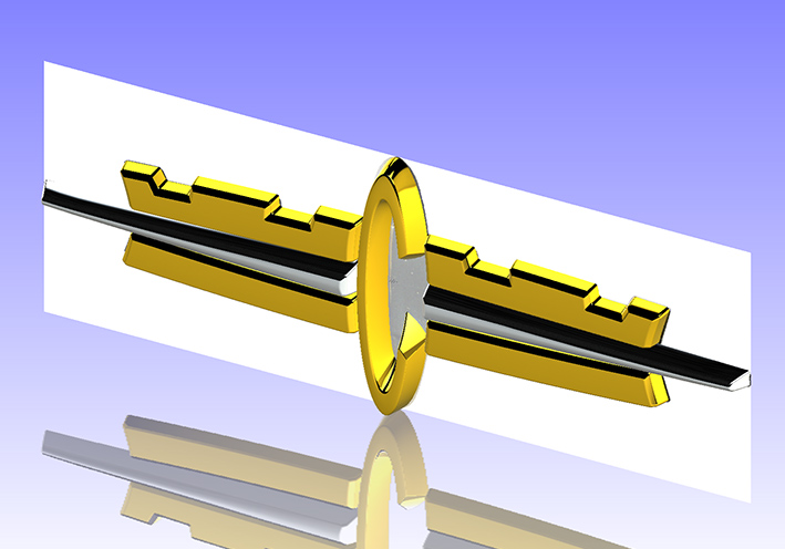 (06 Center Bar modeled.jpg) (06 Center Bar modeled.jpg)
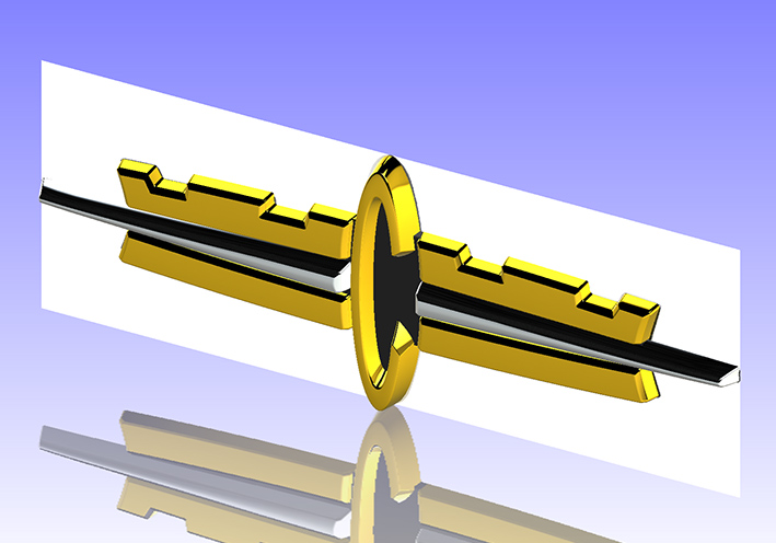 (07 Rear Black Base modeled.jpg) (07 Rear Black Base modeled.jpg)
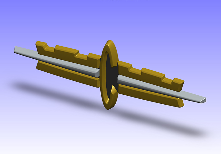 (08 Final Emblem - no RealView.jpg) (08 Final Emblem - no RealView.jpg)
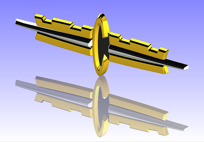 (09 Final Emblem - RealView.jpg) (09 Final Emblem - RealView.jpg)
Attachments
----------------
01 Picture PS inserted.jpg (115KB - 371 downloads)
02 Contour PS inserted.jpg (65KB - 375 downloads)
03 Center Letter C modeled.jpg (76KB - 345 downloads)
04 Upper Ornament modeled.jpg (114KB - 361 downloads)
05 Lower Ornament modeled.jpg (125KB - 360 downloads)
06 Center Bar modeled.jpg (121KB - 344 downloads)
07 Rear Black Base modeled.jpg (122KB - 359 downloads)
08 Final Emblem - no RealView.jpg (85KB - 333 downloads)
09 Final Emblem - RealView.jpg (124KB - 368 downloads)
001 Picture 1962 Chrysler New Yorker Emblem 177x64.8mm (179KB - 375 downloads)
002 Contour 1962 Chrysler New Yorker Emblem 177x64.8mm (176KB - 349 downloads)
|
|
| |
|
Expert
Posts: 1208
Location: SWITZERLAND | For download EPRT-File: 1962 Chrysler New Yorker Emblem This for those who like play on the computer. As the file has 402kB I split it in two files so as can be uploaded: 1962 Chrysler New Yorker Emblem.001 (256kB) 1962 Chrysler New Yorker Emblem.002 (146kB) Then for merge the batch file: Merge 1962 Chrysler New Yorker Emblem.bat (1kB) Download the 3 files in a new folder (named EPRT). Double-click on the batch file and you will get the eDrawing file: 1962 Chrysler New Yorker Emblem.EPRT (402kB) If you don’t have the program already, download “eDrawings” version for free and install (need Version 2016 or newer). This free version doesn't support RealView, you will see as standard. Just open the EPRT File (Password: sermey), then you can turn, zoom, resize and animate automatic the emblem (01) (02) (03). You will encounter a tremendous quality and resolution. Enjoy! - SERGE -
Edited by sermey 2020-04-06 6:25 AM
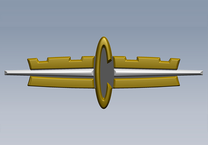 (01 1962 Chrysler New Yorker Emblem Front View.jpg) (01 1962 Chrysler New Yorker Emblem Front View.jpg)
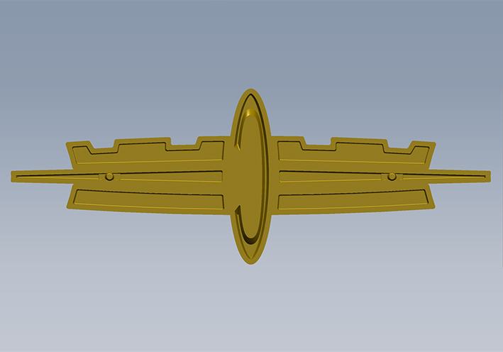 (02 1962 Chrysler New Yorker Emblem Rear View.jpg) (02 1962 Chrysler New Yorker Emblem Rear View.jpg)
 (03 1962 Chrysler New Yorker Emblem.jpg) (03 1962 Chrysler New Yorker Emblem.jpg)
Attachments
----------------
01 1962 Chrysler New Yorker Emblem Front View.jpg (92KB - 334 downloads)
02 1962 Chrysler New Yorker Emblem Rear View.jpg (94KB - 374 downloads)
03 1962 Chrysler New Yorker Emblem.jpg (119KB - 333 downloads)
1962 Chrysler New Yorker Emblem.001 (256KB - 344 downloads)
1962 Chrysler New Yorker Emblem.002 (145KB - 345 downloads)
Merge 1962 Chrysler New Yorker Emblem.bat (0KB - 344 downloads)
|
|
| |
|
Veteran
Posts: 210
Location: Suwanee, GA | Serge,
Nice work, but you missed the recesses at the top and bottom of the "C". I struggled with it and had to get help adding the upper recess to mine. Haven't done the lower one yet.
Robert
 (MLC Sample of Car Logo.JPG) (MLC Sample of Car Logo.JPG)
Attachments
----------------
MLC Sample of Car Logo.JPG (125KB - 378 downloads)
|
|
| |
|
Expert
Posts: 1208
Location: SWITZERLAND | Modification on Letter “C: According the comment of Robert I did minor changes on the Letter “C”. As the emblem was done just quickly, not like the 1959 Dodge parts, some details not have been checked seriously. The upper oval guidelines I found on a too high position. When lofted the top, the “recession” then became bigger. Thanks Robert. As there should be no flat faces at all to appear authentic, no boss/extrude operations have been applied, as done on the presented model of Robert. Instead, all the bodies were created by multiple lofts. Here using 4 spline guidelines (in blue) and tree section profiles (in red) to generate the first quarter (01). This quarter mirrored vertical (02), and then horizontal. All fillets are variable and elliptical as is the emblem (03). Not forget that the top of the letter is curved (04), and that all emblem parts are joined to the backplane (D=2.5mm). The final letter “C” (05) is attached as eDrawing file. Another challenging “game”. – SERGE -
Edited by sermey 2020-04-12 4:43 AM
 (01 Loft Profile.jpg) (01 Loft Profile.jpg)
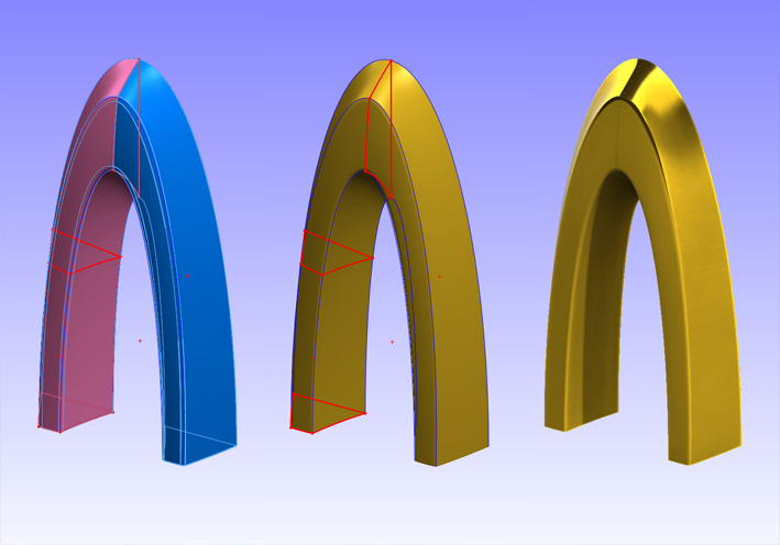 (02 Quarter Mirrored.jpg) (02 Quarter Mirrored.jpg)
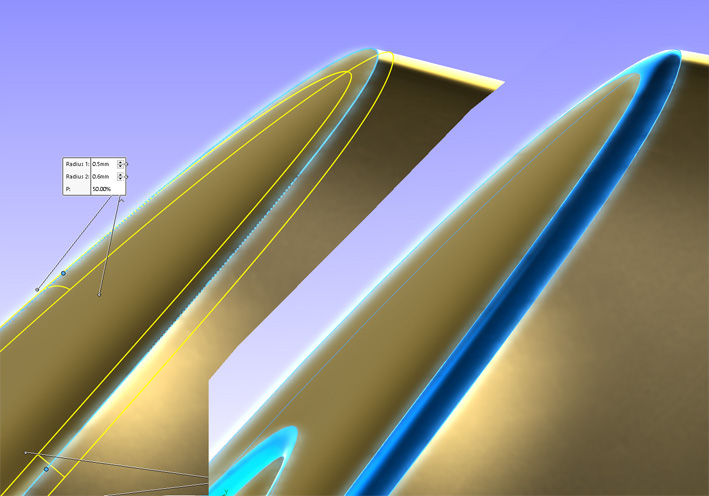 (03 Variable Elliptical Fillet.jpg) (03 Variable Elliptical Fillet.jpg)
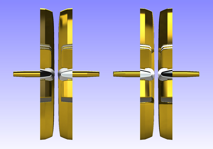 (04 Curved Top.jpg) (04 Curved Top.jpg)
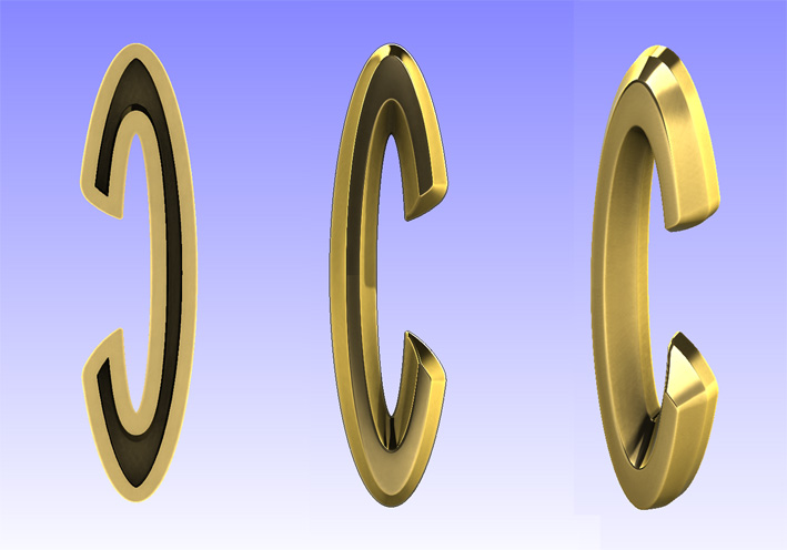 (05 Final Letter C.jpg) (05 Final Letter C.jpg)
Attachments
----------------
01 Loft Profile.jpg (102KB - 355 downloads)
02 Quarter Mirrored.jpg (92KB - 332 downloads)
03 Variable Elliptical Fillet.jpg (115KB - 335 downloads)
04 Curved Top.jpg (79KB - 328 downloads)
05 Final Letter C.jpg (94KB - 363 downloads)
2020-04-11 SW16 Letter C 1962 Emblem.EPRT (181KB - 356 downloads)
|
|
| |
|
Expert
Posts: 1208
Location: SWITZERLAND | License Plate 1959 FLORIDA: For a Convertible I had the choice between a state where it “never rains” (. . . in California) or where is always “sunshine” (...in Florida). Being many times in Miami for business and holidays, obviously I preferred the Sunshine State. I found some nice original 1959 FLORIDA License Plates, especially to get all numbers and the various layouts. A flatbed color scan of the plate produces undistorted pictures in real size for the layout, and the colors of the paint then could exactly be detected. Of course after cleaning the surface to get the color combo as new. The size 303 x 150mm and the thickness I measured 0.8mm. Here my various original plates in isometric view (01)(02)(03)(04). Then two mounted plates including all numbers (05)(06), for those who like create their own configuration, by selecting, copying and paste. Thus I added a blank plate, front and rear view , keeping the background in black for easy cutout (07)(08). Finally the rear view of the first license plate (09).
Now the hobby can go on – with clean hands. – SERGE – 
Edited by sermey 2020-04-14 8:39 AM
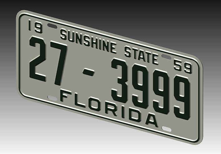 (01 FLORIDA 27-3999.jpg) (01 FLORIDA 27-3999.jpg)
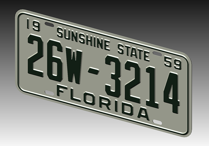 (02 FLORIDA 26w-3214.jpg) (02 FLORIDA 26w-3214.jpg)
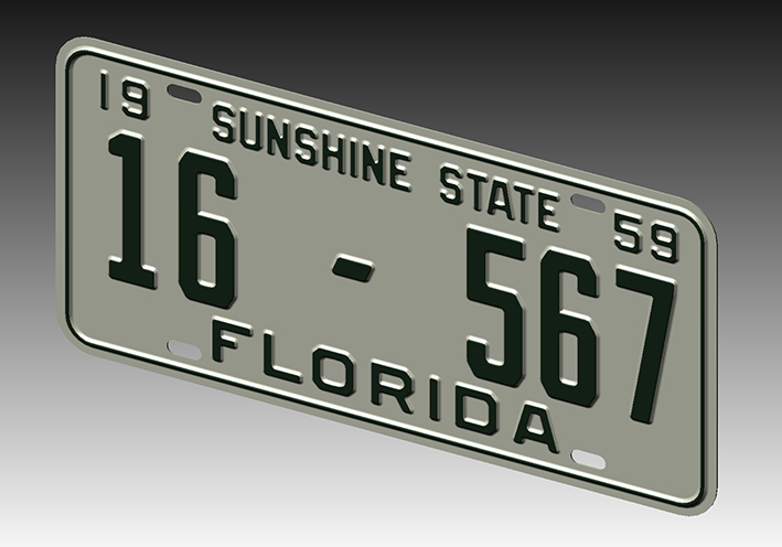 (03 FLORIDA 16-567.jpg) (03 FLORIDA 16-567.jpg)
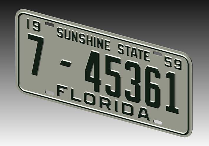 (04 FLORIDA 7-45361.jpg) (04 FLORIDA 7-45361.jpg)
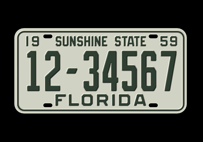 (05 FLORIDA 12-34567.jpg) (05 FLORIDA 12-34567.jpg)
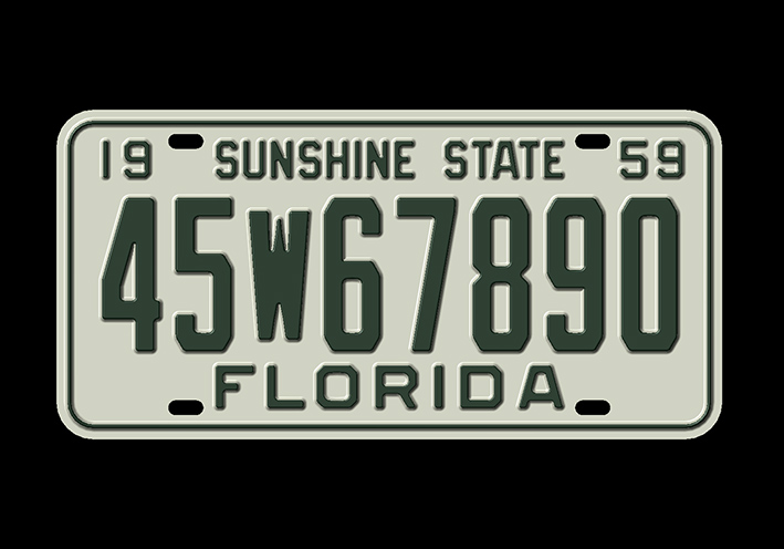 (06 FLORIDA 45w67890.jpg) (06 FLORIDA 45w67890.jpg)
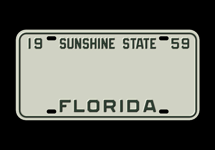 (07 Blank Plate Front View.jpg) (07 Blank Plate Front View.jpg)
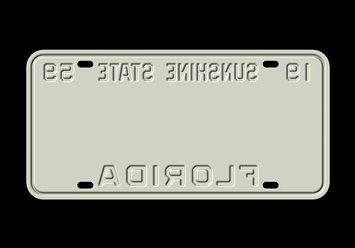 (08 Blank Plate Rear View.jpg) (08 Blank Plate Rear View.jpg)
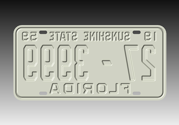 (09 FLORIDA 27-3999 Rear View.jpg) (09 FLORIDA 27-3999 Rear View.jpg)
Attachments
----------------
01 FLORIDA 27-3999.jpg (113KB - 349 downloads)
02 FLORIDA 26w-3214.jpg (115KB - 367 downloads)
03 FLORIDA 16-567.jpg (108KB - 333 downloads)
04 FLORIDA 7-45361.jpg (112KB - 358 downloads)
05 FLORIDA 12-34567.jpg (91KB - 327 downloads)
06 FLORIDA 45w67890.jpg (95KB - 316 downloads)
07 Blank Plate Front View.jpg (64KB - 332 downloads)
08 Blank Plate Rear View.jpg (58KB - 326 downloads)
09 FLORIDA 27-3999 Rear View.jpg (90KB - 364 downloads)
|
|
| |
|
Expert
Posts: 1208
Location: SWITZERLAND | The 1959 DODGE Lost Emblem: another Emblem . . . . . again and again (no comment). - SERGE - Basto - Again and Again (Official Music Video) [HD] - YouTube
Edited by sermey 2020-05-01 10:15 PM
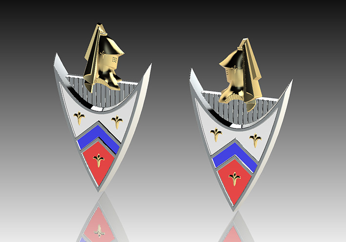 (01 1959 Dodge The Unique Emblem.jpg) (01 1959 Dodge The Unique Emblem.jpg)
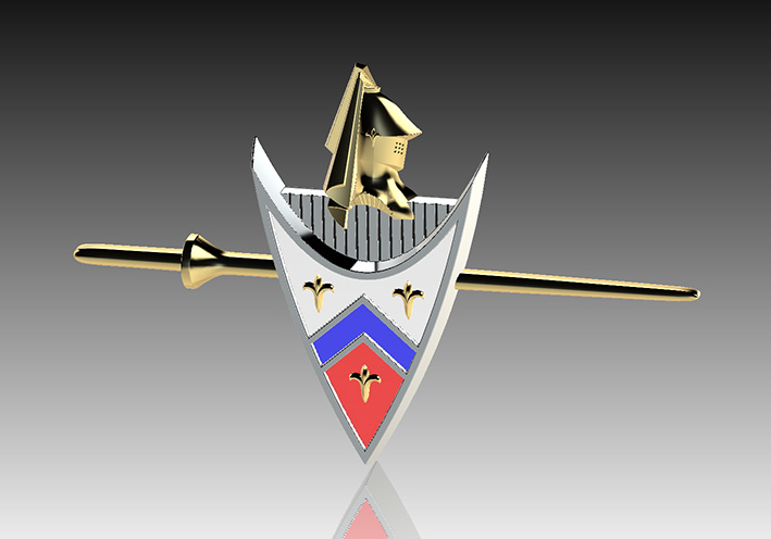 (02 1959 Dodge The Lost Emblem.jpg) (02 1959 Dodge The Lost Emblem.jpg)
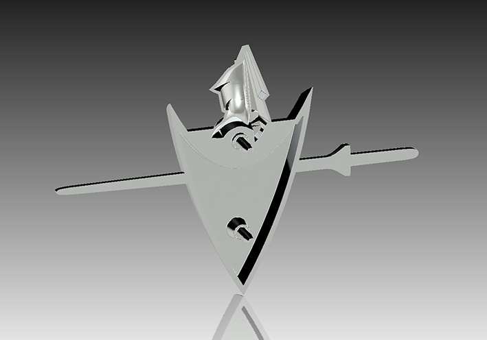 (03 1959 Dodge The Lost Emblem.jpg) (03 1959 Dodge The Lost Emblem.jpg)
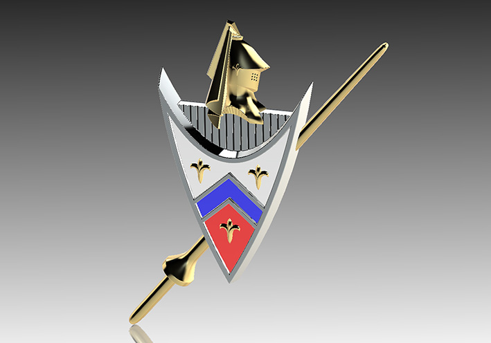 (04 1959 Dodge The Lost Emblem SP.jpg) (04 1959 Dodge The Lost Emblem SP.jpg)
Attachments
----------------
01 1959 Dodge The Unique Emblem.jpg (87KB - 352 downloads)
02 1959 Dodge The Lost Emblem.jpg (66KB - 357 downloads)
03 1959 Dodge The Lost Emblem.jpg (65KB - 330 downloads)
04 1959 Dodge The Lost Emblem SP.jpg (70KB - 321 downloads)
|
|
| |
|
Expert
Posts: 1208
Location: SWITZERLAND | Golden Knight Emblem - King Size: Meanwhile the Knight Emblem was optimized to fit best to the front grille of all 1959 DODGEs, and now is ready for 3D printing. Here some CAD RealView pictures. The Knight was non-linear resized for a harmonic appearance (01). The face is bent according the center angle of the grille, 170deg (02). The length of the studs are cut to match the surface and keep a fixed distance (03). Finally, the surface of the resized Knight will be electro-plated in glossy gold (or chrome) (04). Mounted on the front grille it seems this emblem was always there (05). – SERGE – N.B. The realized Knight Emblem is shown in the thread “Make-up your Car” (to come).
Edited by sermey 2020-09-03 5:17 AM
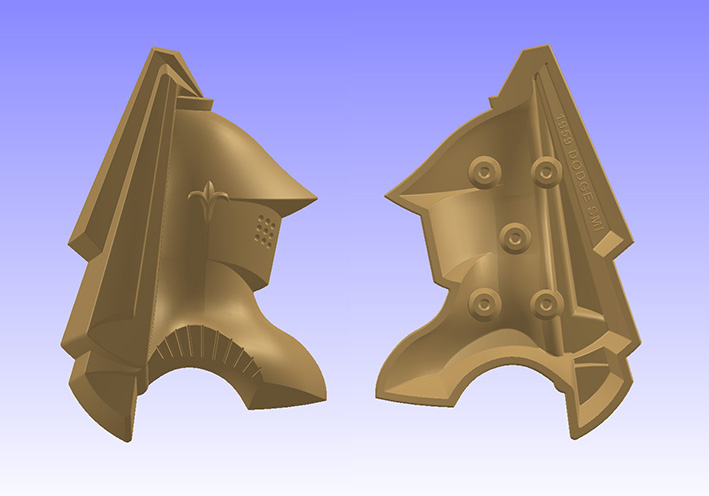 (01 CAD Resine Front - Rear View.jpg) (01 CAD Resine Front - Rear View.jpg)
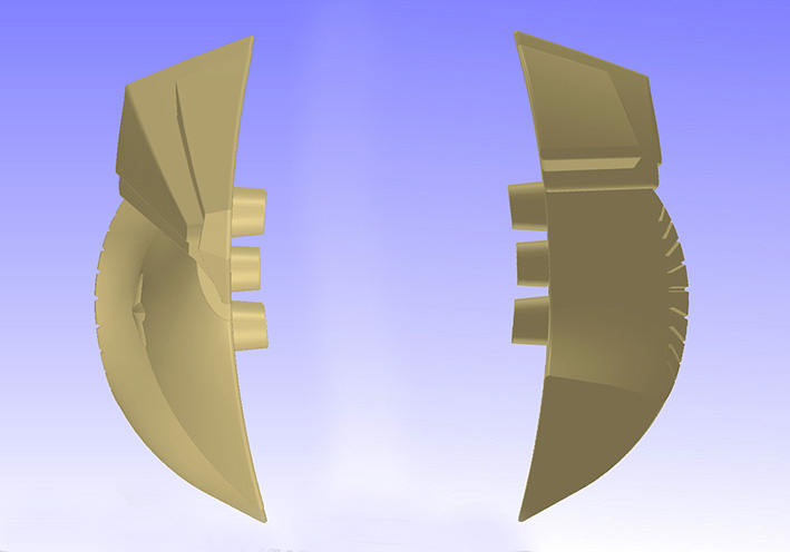 (02 CAD Top - Bottom View.jpg) (02 CAD Top - Bottom View.jpg)
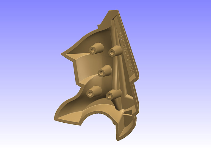 (03 CAD Rear View.jpg) (03 CAD Rear View.jpg)
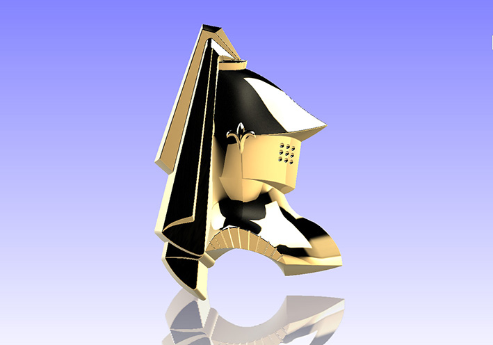 (04 CAD Front View Glossy Golden Plated.jpg) (04 CAD Front View Glossy Golden Plated.jpg)
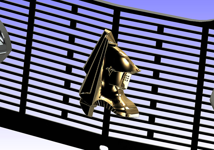 (05 CAD Mounted on the Grille.jpg) (05 CAD Mounted on the Grille.jpg)
Attachments
----------------
01 CAD Resine Front - Rear View.jpg (93KB - 296 downloads)
02 CAD Top - Bottom View.jpg (72KB - 295 downloads)
03 CAD Rear View.jpg (78KB - 285 downloads)
04 CAD Front View Glossy Golden Plated.jpg (91KB - 284 downloads)
05 CAD Mounted on the Grille.jpg (184KB - 292 downloads)
|
|
| |
|
Elite Veteran
Posts: 655
Location: Finland | Serge ,your skills are beyond fantastic...the words are not enough....incomprehensive for me... |
|
| |
|
Expert
Posts: 1208
Location: SWITZERLAND | 3D-Printed Rear Antenna Base: Multiple samples in material and colors, for identify, have been built for functional and mechanical tests (01) (02). The stress test without the antenna tube inside shows the weakest part of the base and gives a magnitude of the maximum load (03). Then the sheetmetal of the car will be somewhat bent! For functional test the Power Antenna Set is mounted on the car (04). The top end can be set according the original length of the original mast, here somewhat shorter (05). As the Antenna Base is black, the rubber looks as intergrated in one. Anyway, a compact and harmonic assembly. The final antenna base then will be glossy chrome electro plated. - SERGE -
Edited by sermey 2020-09-17 1:57 PM
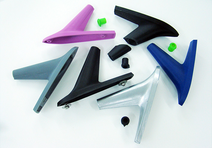 (01 Various 3D-Printed Antenna Bases.jpg) (01 Various 3D-Printed Antenna Bases.jpg)
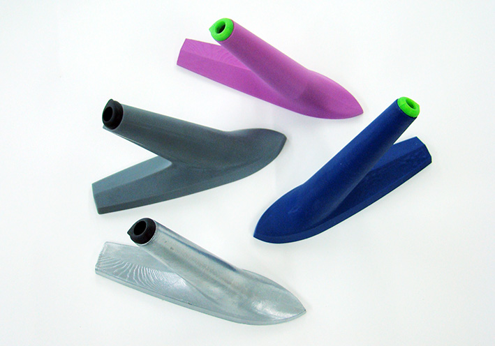 (02 Antenna Bases Top View.jpg) (02 Antenna Bases Top View.jpg)
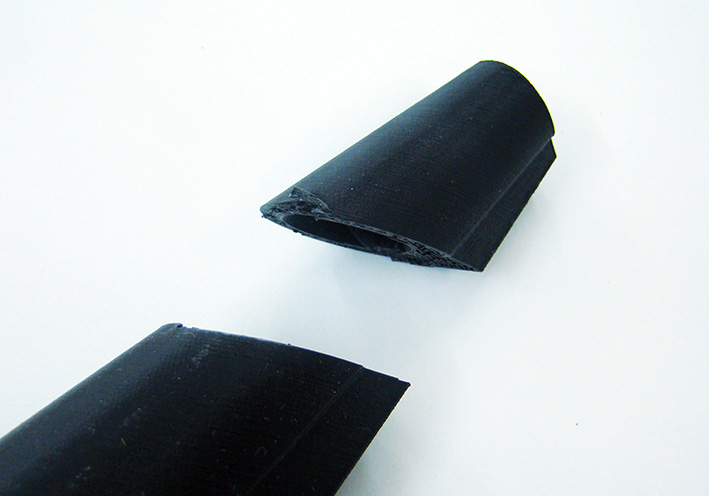 (03 Crash Test.jpg) (03 Crash Test.jpg)
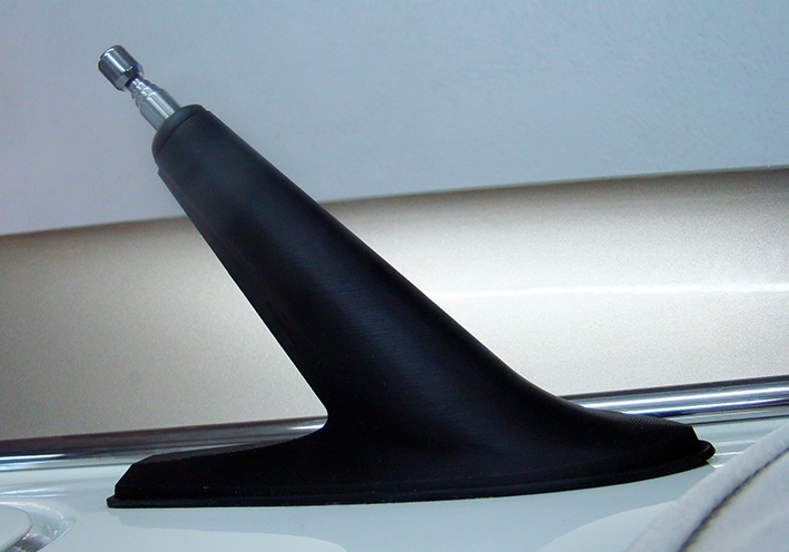 (04 Mounted Assembly.jpg) (04 Mounted Assembly.jpg)
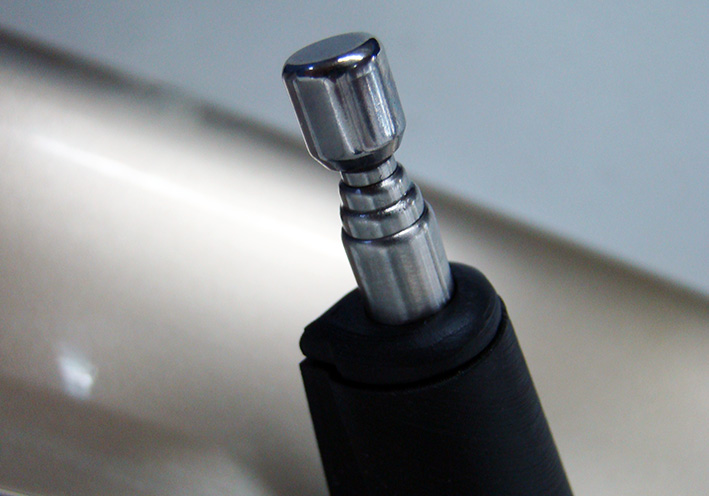 (05 Top End.jpg) (05 Top End.jpg)
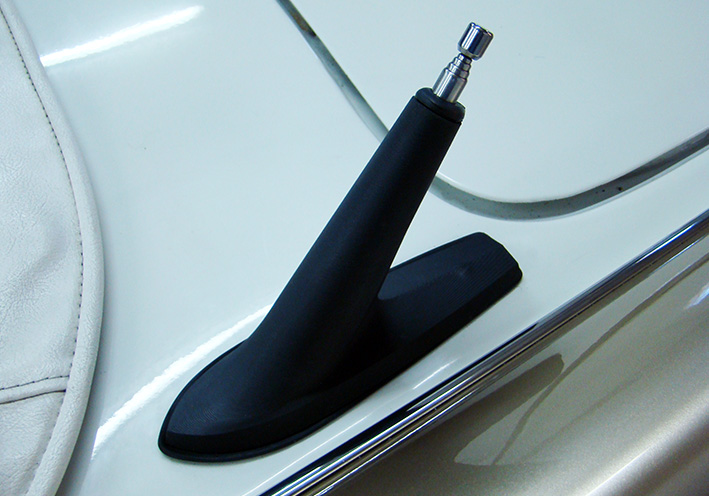 (06 Mounted View.jpg) (06 Mounted View.jpg)
Attachments
----------------
01 Various 3D-Printed Antenna Bases.jpg (116KB - 238 downloads)
02 Antenna Bases Top View.jpg (103KB - 244 downloads)
03 Crash Test.jpg (90KB - 230 downloads)
04 Mounted Assembly.jpg (123KB - 226 downloads)
05 Top End.jpg (106KB - 228 downloads)
06 Mounted View.jpg (131KB - 242 downloads)
|
|
| |
|
Expert
Posts: 1208
Location: SWITZERLAND | Rear Antenna Base Glossy Chrome Plated: The most critical check of a surface is when it is glossy chrome plated. Any unevenness is reflected, also the roughness of the ceiling in my garage. All pairs, left and right, view from various angles, are identical (01). Here another dual side view (02). Beside an original antenna base on my car, a difference is hardly visible (03). The top nut will be relaced by a black TopFix, as the base is designed for. Can say, this is another perfect job! Not for puritans – they prefer originals, in pot metal and some minor pits! - SERGE - :laugh:
Edited by sermey 2020-09-21 6:24 AM
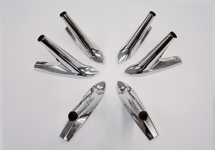 (01 Base Glossy Chrome Plated.jpg) (01 Base Glossy Chrome Plated.jpg)
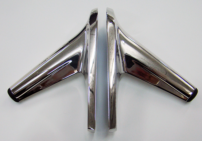 (02 Base Glossy Chrome Plated.jpg) (02 Base Glossy Chrome Plated.jpg)
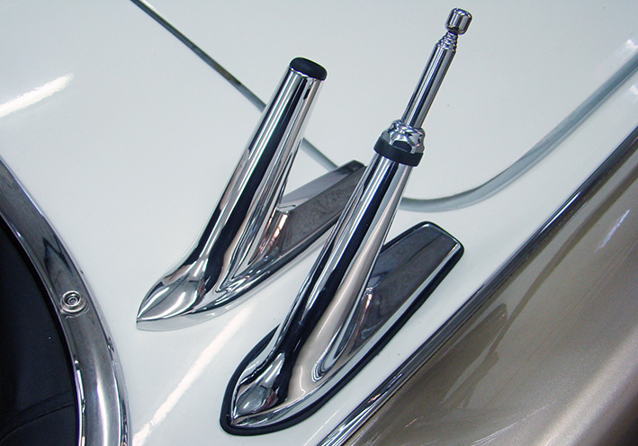 (03 Antenna Base Comparison.jpg) (03 Antenna Base Comparison.jpg)
Attachments
----------------
01 Base Glossy Chrome Plated.jpg (114KB - 231 downloads)
02 Base Glossy Chrome Plated.jpg (132KB - 234 downloads)
03 Antenna Base Comparison.jpg (155KB - 244 downloads)
|
|
| |
|
Expert
Posts: 1208
Location: SWITZERLAND | Cap MIRROR CONTROL: For beginners detailed proceeding, works on any 3D-CAD software. 01 Sketch section and “Revolve” 360deg on axis red. 02 Add some fillets. 03 New surface for set letters along arc, next “Surface-Offset” deep -0.25mm = depht of engravement (left), “Split Line” letters to this surface-offset. 04 Start “Cut-Thicken” each letter separate, from surface-offset up to >0.25mm. 05 All letters cut, “Boss” cam for centering and “CirPattern” 3x 120deg 06 “Edit Appearance” body black, letters surface white Done “Italic” = SolidWorks Commands Good Luck! - SERGE -
Edited by sermey 2022-10-09 11:57 AM
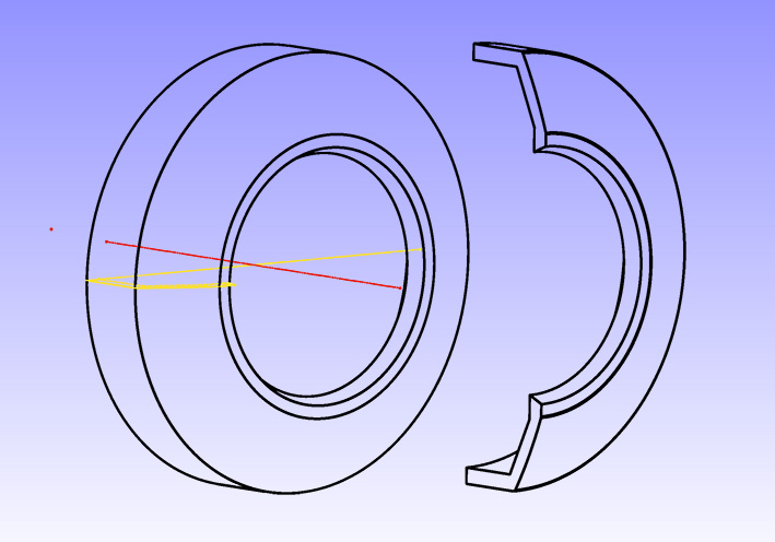 (01 Revolve Section 360deg.jpg) (01 Revolve Section 360deg.jpg)
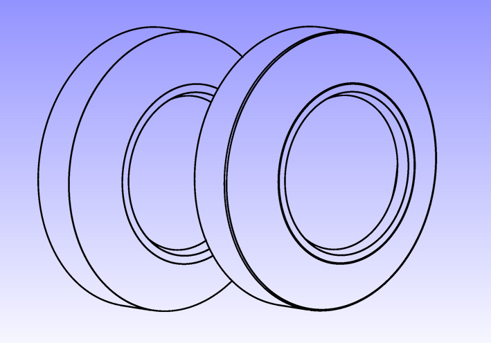 (02 Add some Fillets.jpg) (02 Add some Fillets.jpg)
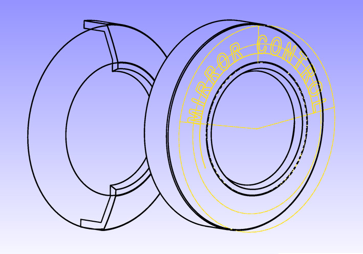 (03 Letters on new Surface along Arc.jpg) (03 Letters on new Surface along Arc.jpg)
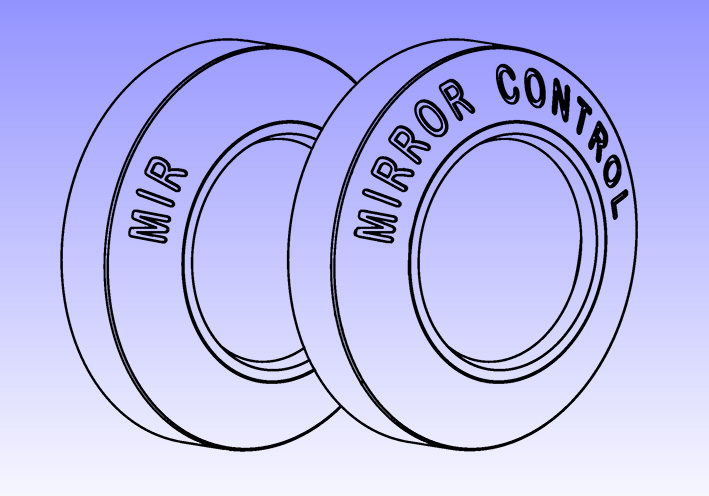 (04 Start Cut Letters from Surface-Offset up.jpg) (04 Start Cut Letters from Surface-Offset up.jpg)
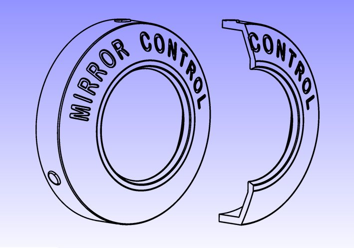 (05 Cut Cap Done for Check.jpg) (05 Cut Cap Done for Check.jpg)
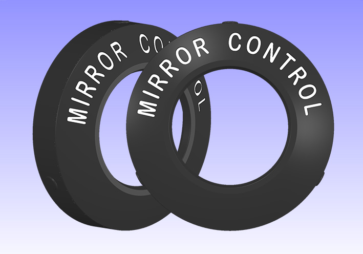 (06 Cap MIRROR CONTROL .jpg) (06 Cap MIRROR CONTROL .jpg)
Attachments
----------------
01 Revolve Section 360deg.jpg (104KB - 82 downloads)
02 Add some Fillets.jpg (102KB - 75 downloads)
03 Letters on new Surface along Arc.jpg (110KB - 79 downloads)
04 Start Cut Letters from Surface-Offset up.jpg (124KB - 93 downloads)
05 Cut Cap Done for Check.jpg (123KB - 78 downloads)
06 Cap MIRROR CONTROL .jpg (85KB - 80 downloads)
|
|
| |
|
Regular
Posts: 59
| Makes a grown man weep with joy…
What are the chances you would be willing to hold and record a tutorial session so we can all start doing this — or at least give it a shot? |
|
| |
|
Expert
Posts: 1208
Location: SWITZERLAND | Thanks James for your kind comment. There are many tutorials available in the internet. With some applied samples of FWL-parts I try to provide some variety in this mostly mechanical oriented site. For me this is just as another game. As you may observe in my threads, there are minor interested guys to participate in this direction. Always pleased to read some encouraging words like yours. - SERGE - |
|
| |
|
Expert
Posts: 1208
Location: SWITZERLAND | Door Stop: The mechanical function of the door stop is the same for 1957 – 1959 Plymouth / Dodge, may-be as well for other mopars. They all don’t have an intermediate door catch. To find solutions for this option, the disposable space and the function should be analysed by 3D-Modelling. The main part is the bracket unit (01). Built-in parts the bracket, a damping grommet, a retaining washer, and two stop springs fixed with a rivet (02). The bracket unit, inserted from rear, is lateral guided and free movable along the slot (03)(04). At fully open door, the damping grommet marks the end stop (05), can see the springs to trap the door (06). Not shown the hinge with the pin, entering partly in the door. Left and right door are identical, just mirrored. These CAD-views of a white painted car visualize the function, and helps for design a much-needed option - an intermediate door catch (07). - SERGE -
Edited by sermey 2022-11-21 5:01 PM
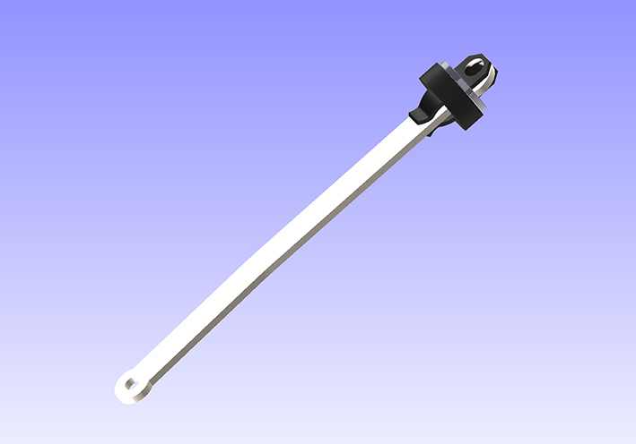 (01 Bracket Unit.jpg) (01 Bracket Unit.jpg)
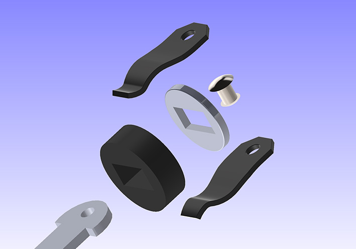 (02 Bracket Unit Disassembled.jpg) (02 Bracket Unit Disassembled.jpg)
 (03 Bracket Unit Mounted.jpg) (03 Bracket Unit Mounted.jpg)
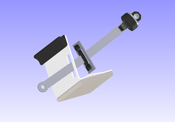 (04 Top View Unit Mounted.jpg) (04 Top View Unit Mounted.jpg)
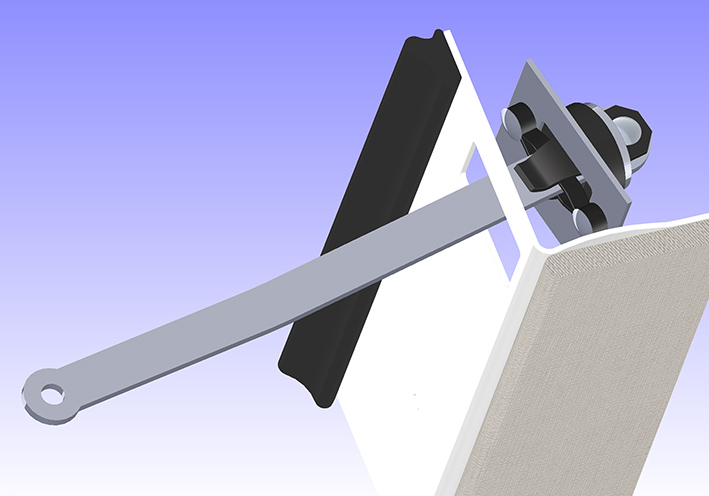 (05 Top View Door Fully Open.jpg) (05 Top View Door Fully Open.jpg)
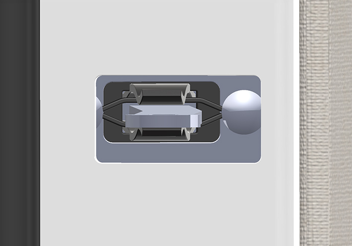 (06 Front View Door Fully Open.jpg) (06 Front View Door Fully Open.jpg)
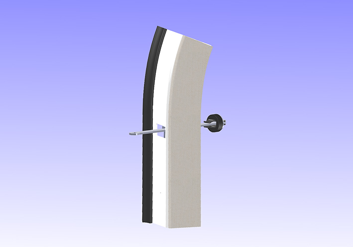 (07 Overview Door.jpg) (07 Overview Door.jpg)
Attachments
----------------
01 Bracket Unit.jpg (53KB - 65 downloads)
02 Bracket Unit Disassembled.jpg (60KB - 61 downloads)
03 Bracket Unit Mounted.jpg (65KB - 64 downloads)
04 Top View Unit Mounted.jpg (67KB - 67 downloads)
05 Top View Door Fully Open.jpg (97KB - 67 downloads)
06 Front View Door Fully Open.jpg (72KB - 60 downloads)
07 Overview Door.jpg (55KB - 67 downloads)
|
|
| |