|
|
Expert 5K+
Posts: 9900
   
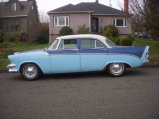
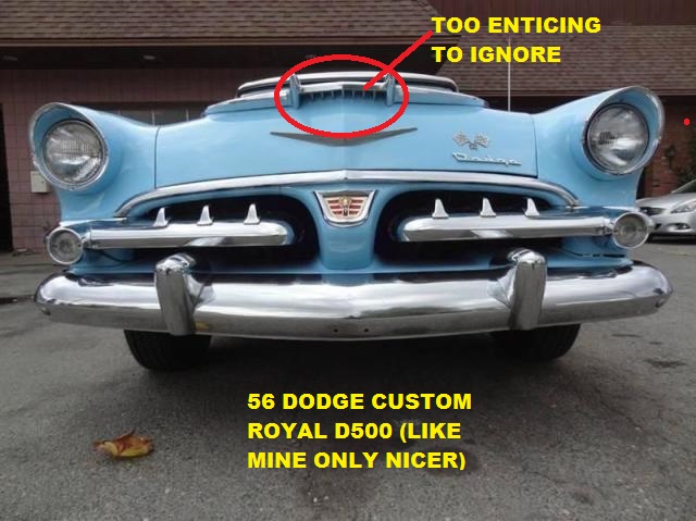
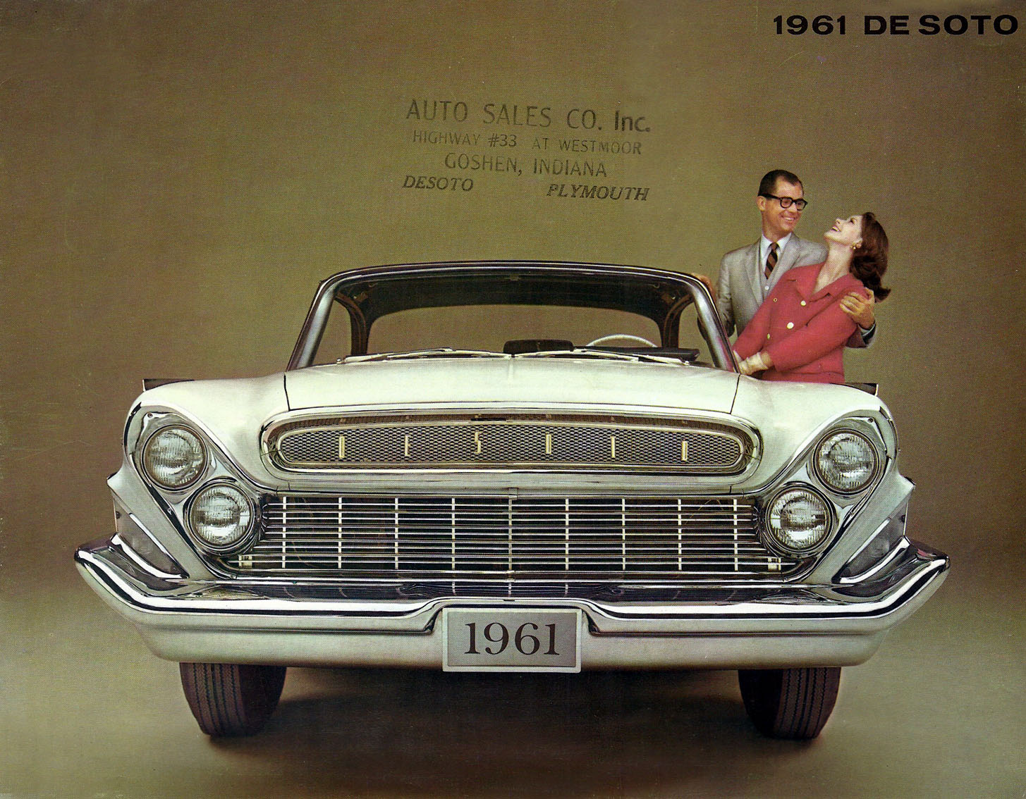
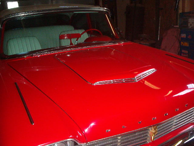
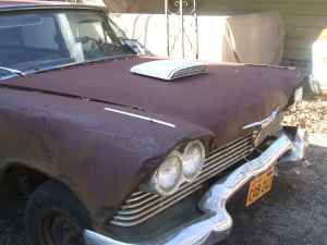
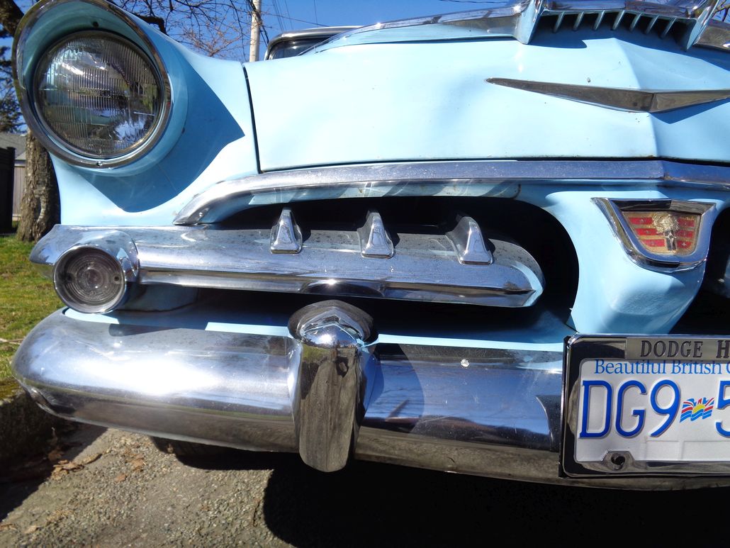
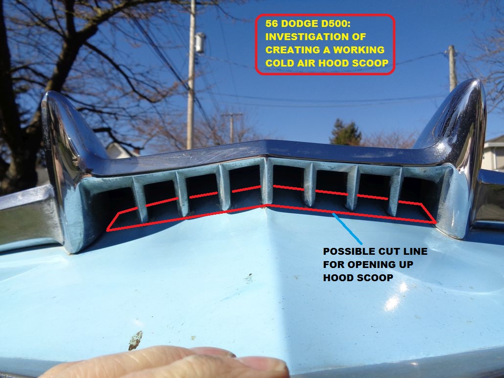
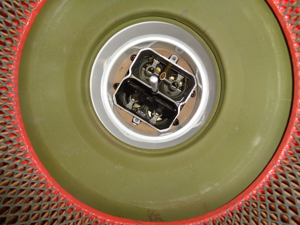
Location: Lower Mainland BC | Anybody have any details (photos, links, etc) on how the 53 Dodge Coronet V8 functional hood scoop actually worked (as in the ducting towards the aircleaner or...)?? I look at the hood ornament on my 56 Dodge and notice the potential for a functional hood scoop that is too enticing to ignore.

 (56DodgeCustomRoyalD500PotentialHoodScoop.jpg) (56DodgeCustomRoyalD500PotentialHoodScoop.jpg)
Attachments
----------------
 56DodgeCustomRoyalD500PotentialHoodScoop.jpg (95KB - 721 downloads) 56DodgeCustomRoyalD500PotentialHoodScoop.jpg (95KB - 721 downloads)
|
|
| |
|

 
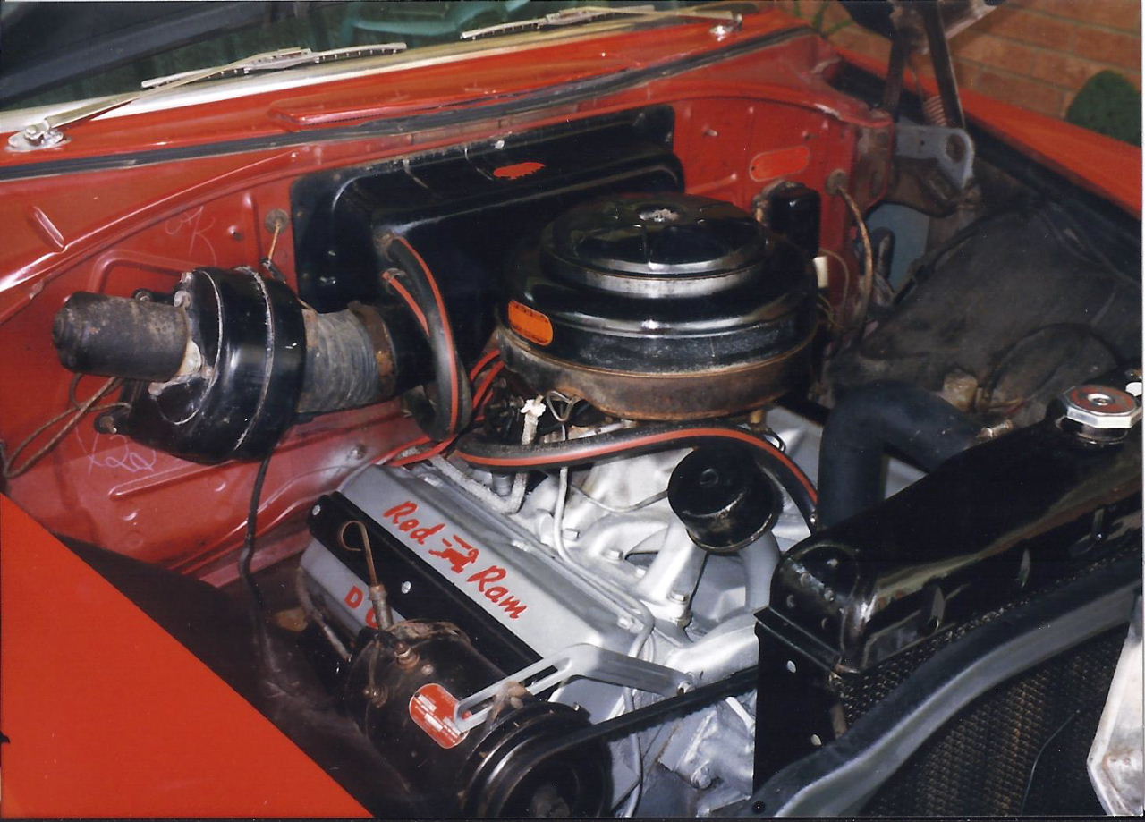
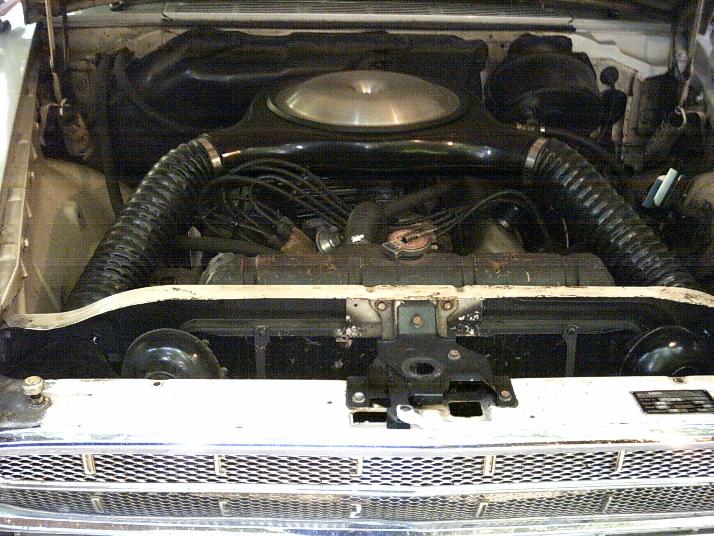
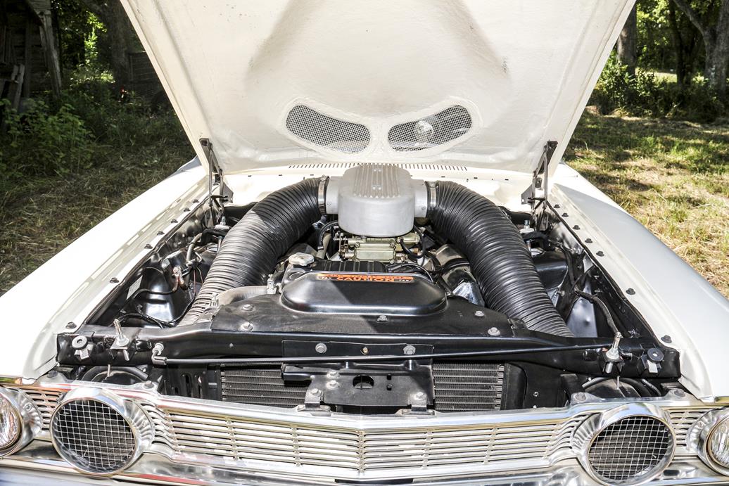
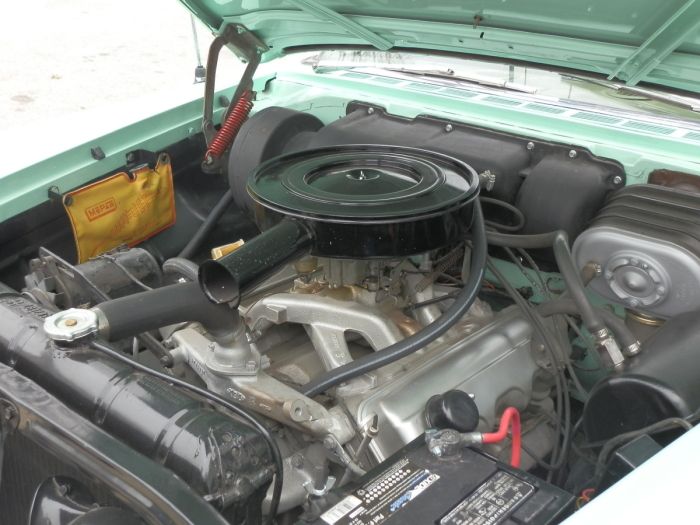
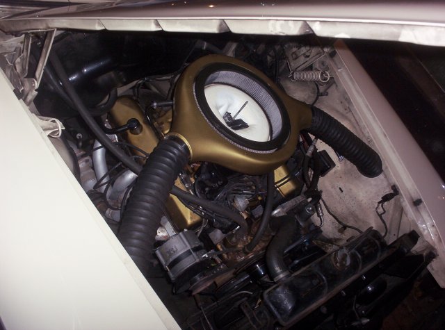
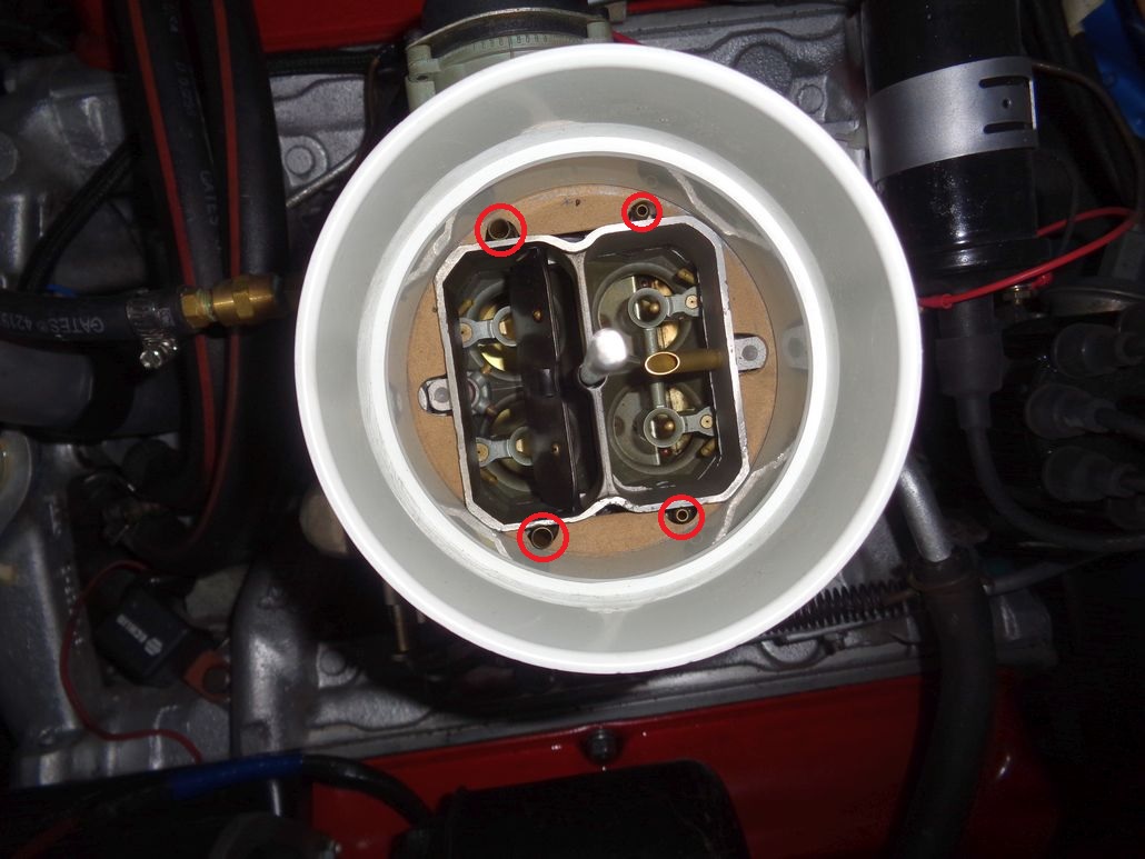
Location: Under the X in Texas | Photo of the engine compartment of a '53 Coronet I owned about 17 years ago. There was no special ducting or anything of the sort. Don't read too much into what the marketing and advertising departments write into the sales brochures.
 (53Dodge7.jpg) (53Dodge7.jpg)
Attachments
----------------
53Dodge7.jpg (187KB - 732 downloads)
|
|
| |
|

Location: The Mile High City | So you are thinking of cutting a hole in your '56 hood? I can't imagine a hole in the hood would have any effect on performance - might look cool though!
It seems like you would have to fabricate a direct intake into the air cleaner to make it function. Still, I don't know if you would see a performance difference... |
|
| |
|
Expert 5K+
Posts: 9900
Location: Lower Mainland BC | Lancer Mike - 2017-01-29 6:11 PM So you are thinking of cutting a hole in your '56 hood? I can't imagine a hole in the hood would have any effect on performance - might look cool though!
It seems like you would have to fabricate a direct intake into the air cleaner to make it function. Still, I don't know if you would see a performance difference...
Yeah, that is the idea that I am toying with. I am going to take the big chrome bit off anyway when the weather gets better and I paint the top of the hood. While I am there I might cut a hole behind the louvered "scoop" portion. The trick would be running a cold air duct from the (hidden) hood "scoop" to the air cleaner. Obstacles in the way include the radiator support bulk head and the radiator.
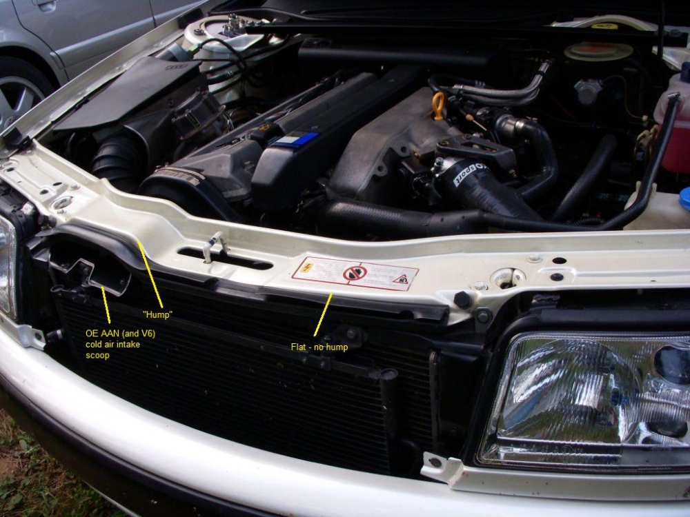
Both of my other two cars (Audis) have factory cold air induction. Inlet scoops at/through the rad support and then ducting to the air cleaner (box). Knowing that cold air is better for performance and see that potential scoop on the 56 is very enticing. I would probably have to go to a snorkel type air cleaner and create ducting with fiberglass over a foam core. Probably just a pipe dream. But an enticing one to me.
The 1993 UrS4 line-line 5 20 valve 350 hp turbo:
The 1994 UrS4 32 Valve 4.2L V8:
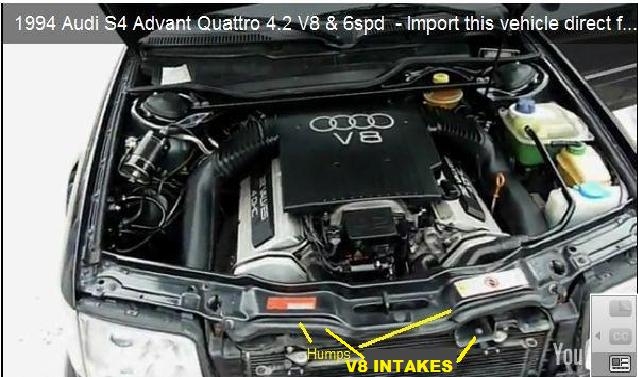
Lock carrier (rad support) 101: http://forums.quattroworld.com/s4s6/msgs/61928.phtml |
|
| |
|

Expert 5K+
Posts: 7400
Location: northern germany | Lancer Mike - 2017-01-29 6:11 PM
So you are thinking of cutting a hole in your '56 hood? I can't imagine a hole in the hood would have any effect on performance - might look cool though!
it certainly has a positive effect on performance and efficiency if you can somehow direct the incoming air to the carb. cold air makes more power, engine idles smoother. the ram effect is proven too but only at higher speeds.
not a big fan of cutting in original parts but that would be too hard to resist considering the benefits and look of it. i'm using a cold/ram air system in my golden commando fury and highly recommend that.
great find by the way dave! i didn't know about that and that in an early 50s car! |
|
| |
|
Expert 5K+
Posts: 9900
Location: Lower Mainland BC | 1960fury - 2017-05-21 1:05 PM
Lancer Mike - 2017-01-29 6:11 PM
So you are thinking of cutting a hole in your '56 hood? I can't imagine a hole in the hood would have any effect on performance - might look cool though!
it certainly has a positive effect on performance and efficiency if you can somehow direct the incoming air to the carb. cold air makes more power, engine idles smoother. the ram effect is proven too but only at higher speeds. not a big fan of cutting in original parts but that would be too hard to resist considering the benefits and look of it. i'm using a cold/ram air system in my golden commando fury and highly recommend that.
great find by the way dave! i didn't know about that and that in an early 50s car!
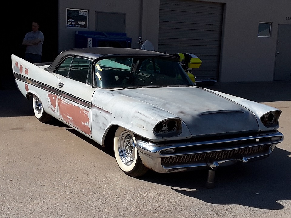
I just scored a very nice 56 Dodge hood ornament on eBay and was polishing it up nicely yesterday, looking at the "scoop". Thanks for replying. It's serving as a memory jog.
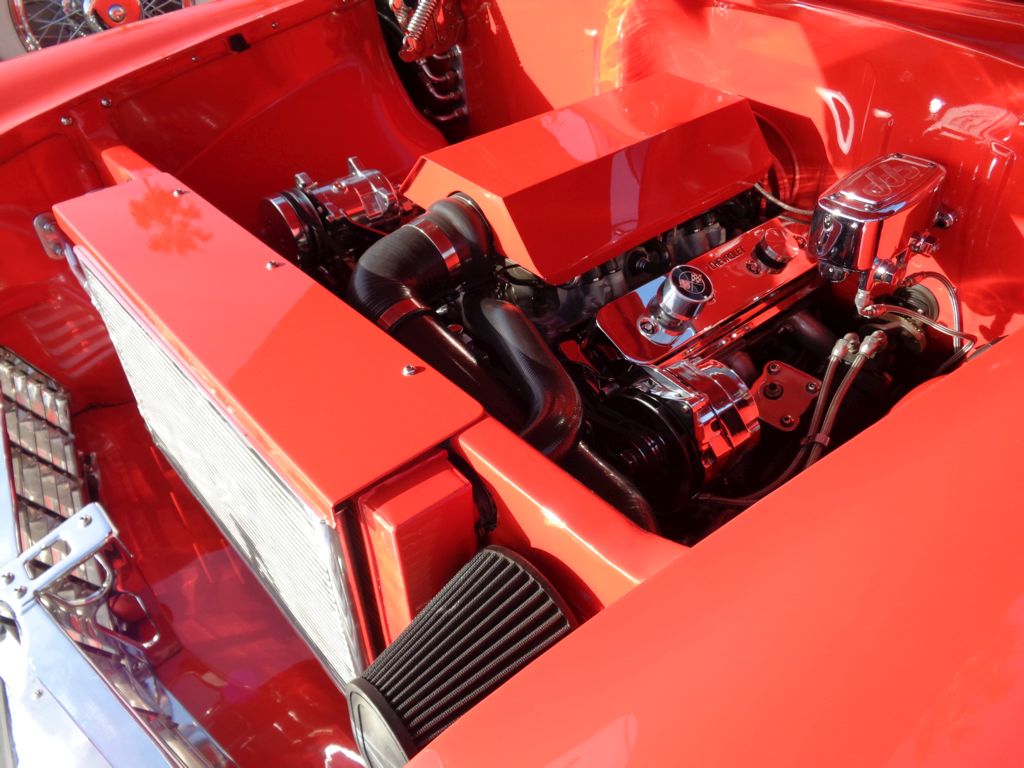
On my recent trip to California, at one low key/ad hoc "Ruby's" parking lot car show, there was a 55 chev with a later fuel injected V8 and it had a cold air intake through the rad support. My car isn't that important that I couldn't put a hole in the rad support if I wanted to.
Dave F.
 (55ChevyWithColdAirInduction.jpg) (55ChevyWithColdAirInduction.jpg)
Attachments
----------------
55ChevyWithColdAirInduction.jpg (131KB - 738 downloads)
|
|
| |
|
Expert 5K+
Posts: 7400
Location: northern germany | heres the system i put on my ex 61 desoto coupe. went 130+ easily with the high mileage factory detuned low compression 361.
 (desoto17.jpg) (desoto17.jpg)
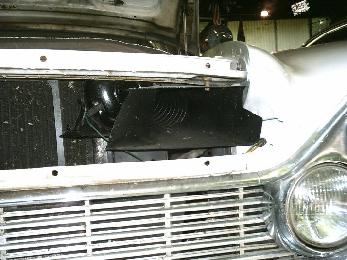 (desoto16.jpg) (desoto16.jpg)
Attachments
----------------
desoto17.jpg (89KB - 711 downloads)
desoto16.jpg (69KB - 703 downloads)
|
|
| |
|
Expert 5K+
Posts: 9900
Location: Lower Mainland BC | 1960fury - 2017-05-21 5:12 PM heres the system i put on my ex 61 desoto coupe. went 130+ easily with the high mileage factory detuned low compression 361.
Very nice. Very nice indeed.
 |
|
| |
|
Expert
Posts: 3575
Location: Netherlands | That last pic, I could have sworn that's the front of a '59 Buick Electra...
|
|
| |
|
Expert 5K+
Posts: 9900
Location: Lower Mainland BC | BigBlockMopar - 2017-05-22 5:06 AM That last pic, I could have sworn that's the front of a '59 Buick Electra...
Interesting thought. Both have canted dual headlights (but the angles are different)
1961 Desoto canted headlights (quite vertical)
1959 Buick (canted but laid down more than the Desoto (or Chyrsler)):

1961 Chrysler:
 |
|
| |
|

Expert
Posts: 3967
Location: DFW, TX | I don't think you could just put a "tube" that leads from the hood scoop, over the radiator, and up to the snorkel air cleaner. What would you have when opening the hood? A big dangly dryer hose? :D
Maybe you could create an inlet tract that would form a seal when the hood is closed.
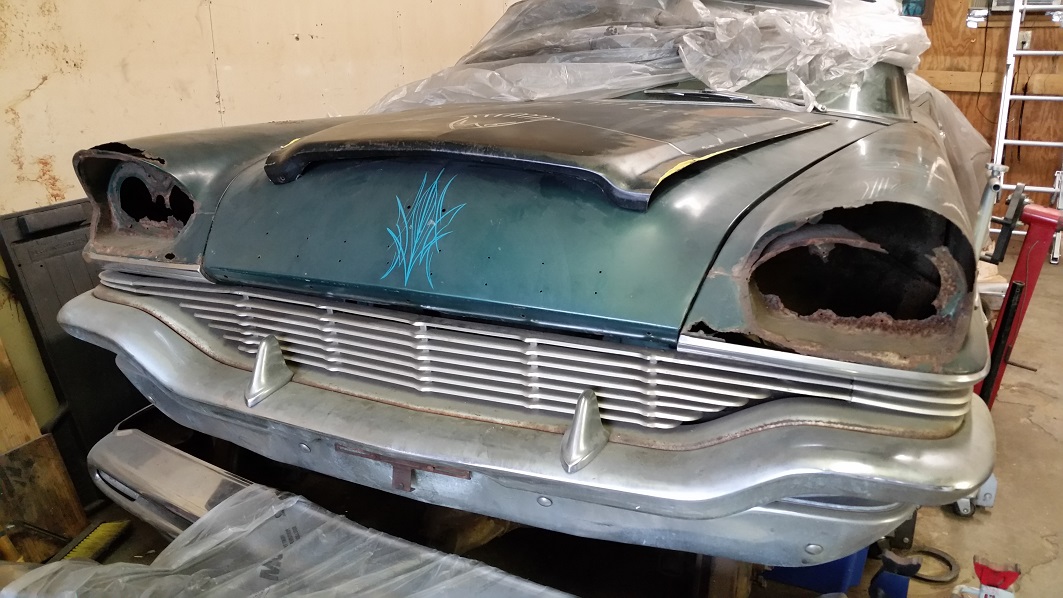
I'm building a scoop for the hood of my Chrysler. I haven't decided yet if it will be "functional," as most that you think would be, actually are not. The engine compartment can build a lot of pressure in cars with open grilles. At certain speeds, air can actually come out of an open scoop.
It's further along than this, but gives you an idea.
 (20170402_144621.jpg) (20170402_144621.jpg)
Attachments
----------------
20170402_144621.jpg (192KB - 734 downloads)
|
|
| |
|
Expert
Posts: 3575
Location: Netherlands | Air scoops need to be sealed off completely from the rest of the engine bay otherwise they might/will work the opposite way like Danny mentions.
An incospicous lower front spoiler could help lower the underhood pressures at higher speeds.
Lower underhood air pressure also prevents steering to become overly light and 'vague' at high speeds.
|
|
| |
|

Expert 5K+
Posts: 9664
Location: So. Cal | Danny, did you form that scoop yourself or cut it from another application? Those are impressive metal forming skills if you made it yourself. It fits the hood really well. |
|
| |
|
Expert
Posts: 3967
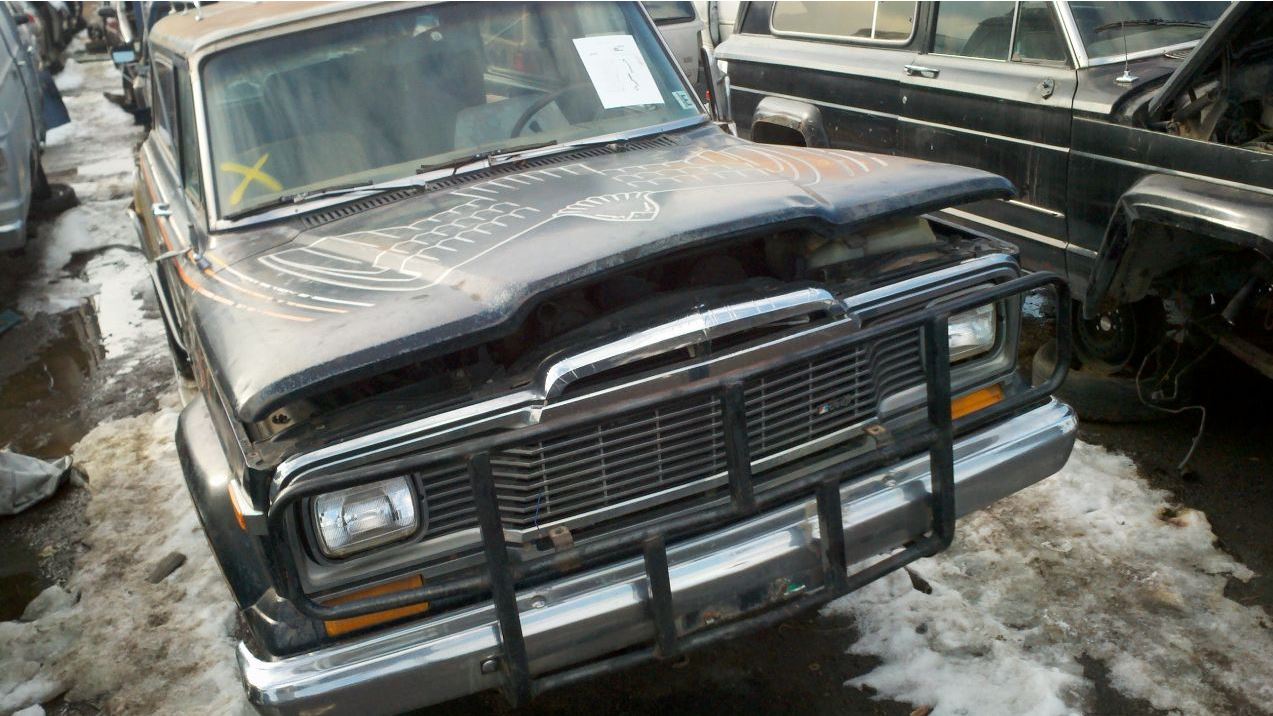
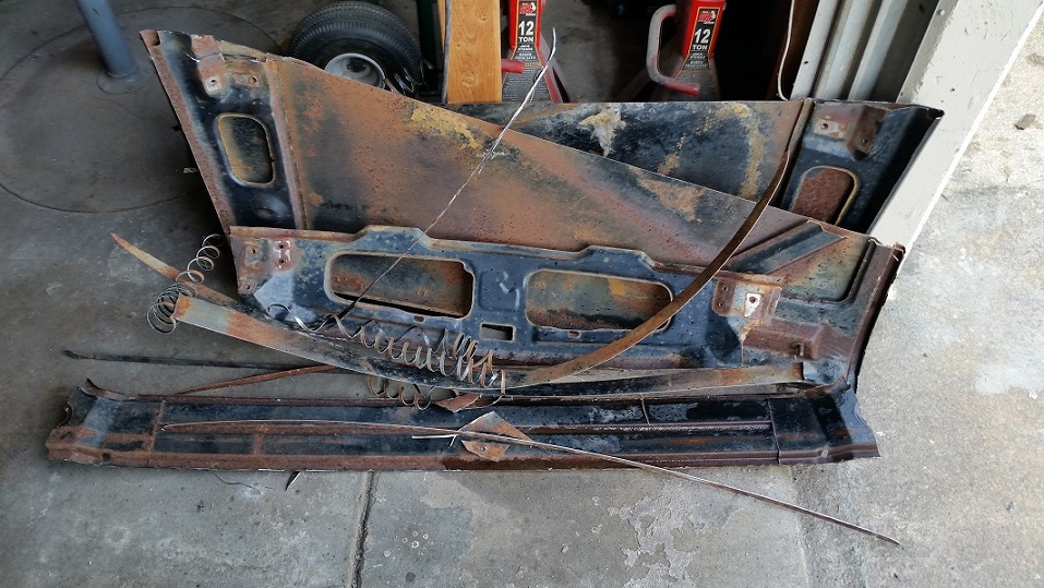
Location: DFW, TX | Nathan, the scoop is made from the center section of an old Jeep hood.
 (1.JPG) (1.JPG)
 (3.jpg) (3.jpg)
 (4.jpg) (4.jpg)
Attachments
----------------
1.JPG (169KB - 694 downloads)
3.jpg (242KB - 711 downloads)
4.jpg (216KB - 729 downloads)
|
|
| |
|
Expert 5K+
Posts: 9664
Location: So. Cal | Very resourceful, I like it. |
|
| |
|
Expert
Posts: 1906
Location: Ontario, Canada | Powerflite - 2017-05-23 12:50 PM
Very resourceful, I like it. :)
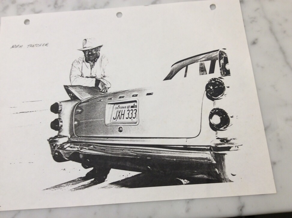
Here is one for the 57/58 Dodge guys.
"Factory" racing team?? Who knows??
Greg
 (image.jpg) (image.jpg)
Attachments
----------------
image.jpg (186KB - 710 downloads)
|
|
| |
|
Expert
Posts: 1906
Location: Ontario, Canada | Note the clip to tie down the hood!
That photo courtesy of the late Neil Vedder.
Greg |
|
| |
|
Expert 5K+
Posts: 7400
Location: northern germany | 56D500boy - 2017-05-21 8:02 PM
1960fury - 2017-05-21 5:12 PM heres the system i put on my ex 61 desoto coupe. went 130+ easily with the high mileage factory detuned low compression 361.
Very nice. Very nice indeed.
: )
thanks, these cars push a lot of air at high speeds and i like the idea that some of that pressurised air is used as an advantage. it works just great. heres the system in my 60 fury coupe. i had troubles with blown air box seals above 130 mph. (disregard the blue blob:)
 (ramairk1.jpg) (ramairk1.jpg)
 (ramairk2.jpg) (ramairk2.jpg)
 (ramairk3.jpg) (ramairk3.jpg)
Attachments
----------------
ramairk1.jpg (130KB - 682 downloads)
ramairk2.jpg (106KB - 680 downloads)
ramairk3.jpg (81KB - 715 downloads)
|
|
| |
|

Expert
Posts: 1622
Location: Seville, OH | LD3 Greg - 2017-05-23 11:54 PM
Powerflite - 2017-05-23 12:50 PM
Very resourceful, I like it. :)
Here is one for the 57/58 Dodge guys.
"Factory" racing team?? Who knows??
Greg
That is Norm Thatcher's D-501. |
|
| |
|
Expert
Posts: 3967
Location: DFW, TX | User Mike P used a scoop from a '63 Thunderbird to clear the air cleaner on his '57 sedan.
(more pics on this thread)
 (PLy hood scoop.JPG) (PLy hood scoop.JPG)
Attachments
----------------
PLy hood scoop.JPG (50KB - 705 downloads)
|
|
| |
|

Expert
Posts: 1316
Location: Belgium, 40 miles south of Brussels | 1960fury - 2017-05-24 2:10 PM
i had troubles with blown air box seals above 130 mph
130 mph ???? 210 kph ???
Seriously ? |
|
| |
|
Expert 5K+
Posts: 7400
Location: northern germany | Chrome58 - 2017-05-25 5:01 AM
1960fury - 2017-05-24 2:10 PM
i had troubles with blown air box seals above 130 mph
130 mph ???? 210 kph ???
Seriously ?
top speed is way beyond that. i guess since 1959 the laws of physics have not changed. stuck with OE parts including the tiny single afb and the restrictive OE intake the pettys hit officially 150+ mph in their 60 plymouths.
my car makes more power, weights less and uses some performance enhancing "tricks" not available for 1960 stock cars. at 145 mph the pedal is not 100% floored. its a 6.3 liter that revs to 6k in a feather light unibody with a 2.93 rear end.
i once had an old opel diesel wagon with a @ 105 hp high mileage motor that could hit (indicated) 123 mph on a good day. 130 mph with 400+ hp, nothing special.
Edited by 1960fury 2017-05-25 8:12 AM
|
|
| |
|
Expert
Posts: 1906
Location: Ontario, Canada | Swept57 - 2017-05-24 9:08 AM
LD3 Greg - 2017-05-23 11:54 PM
Powerflite - 2017-05-23 12:50 PM
Very resourceful, I like it. :)
Here is one for the 57/58 Dodge guys.
"Factory" racing team?? Who knows??
Greg
That is Norm Thatcher's D-501.
Yeah, it is Norm Thatchers car but is it a super D or a 501?
Greg |
|
| |
|
Expert
Posts: 1906
Location: Ontario, Canada | LD3 Greg - 2017-05-25 11:52 PM
Swept57 - 2017-05-24 9:08 AM
LD3 Greg - 2017-05-23 11:54 PM
Powerflite - 2017-05-23 12:50 PM
Very resourceful, I like it. :)
Here is one for the 57/58 Dodge guys.
"Factory" racing team?? Who knows??
Greg
That is Norm Thatcher's D-501.
Yeah, it is Norm Thatchers car but is it a super D or a 501?
Greg
I meant to include this.
 (image.jpg) (image.jpg)
Attachments
----------------
image.jpg (118KB - 706 downloads)
|
|
| |
|
Expert
Posts: 1906
Location: Ontario, Canada | Nothing on the trunk lid!
Greg |
|
| |
|
Expert 5K+
Posts: 9664
Location: So. Cal | Maybe he was in stealth mode and took it off. The couple that raced my '68 Barracuda on the streets in the 70's put a 440 in it, but installed 273 emblems on the fenders to fool potential contenders. Although in Norm's case, the non-stock hood scoop would probably give it away. |
|
| |
|
Expert
Posts: 1622
Location: Seville, OH | LD3 Greg - 2017-05-25 11:57 PM
Nothing on the trunk lid!
Greg
I identified Norm's car as a D-501 based on what Neil told me. Some of the early 501's didn't get the emblem, they also didn't have a special body code either. |
|
| |
|
Expert 5K+
Posts: 9900
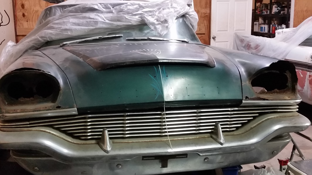
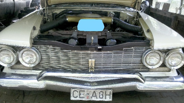
Location: Lower Mainland BC | These 1956 Dodge hood eBay photos don't make it easier to resist cutting and air scoop slot.
 
Just sayin'

|
|
| |
|
Expert
Posts: 3575
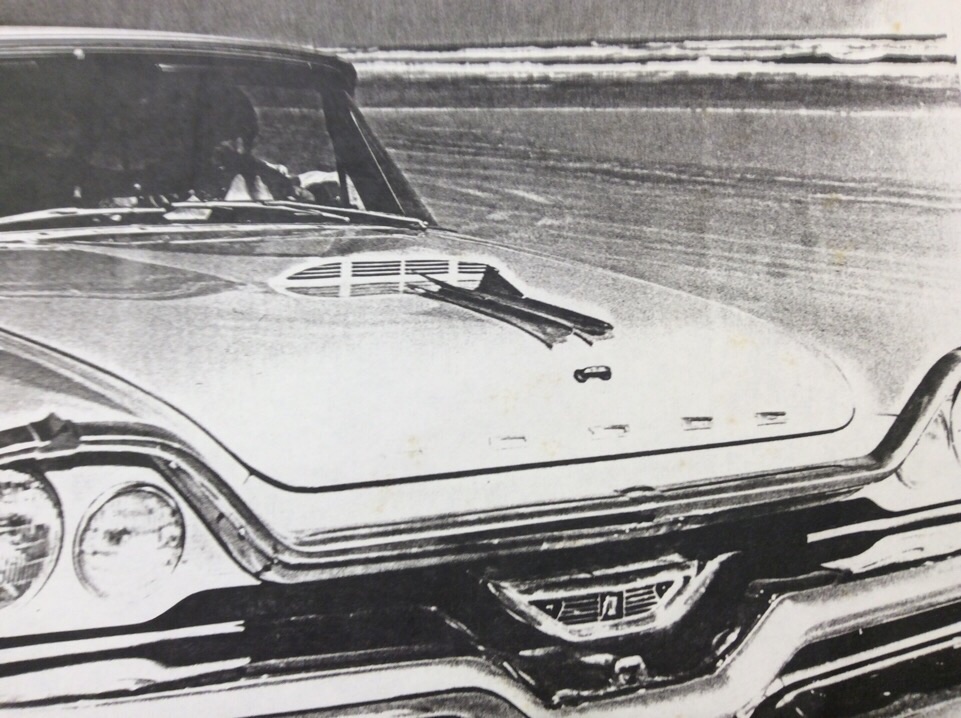
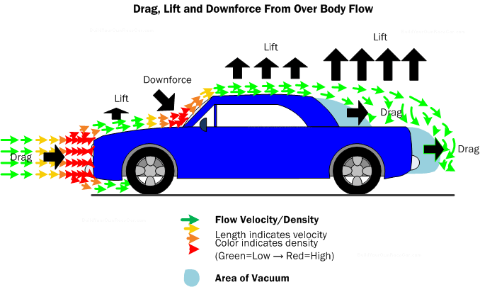
Location: Netherlands | "Forward looking air scoops"... (get it? ) need to be at the very front of a hood.
Airscoops that are positioned halfway down and in the center of a hood aren't very effective as there's not much airpressure in that area.
Fast flowing air encountering the hood tends to curve up a little higher then the hood itself in the center, only to come 'down' again near the windshield, where it's swooped up again over the roof of the car.
|
|
| |
|
Expert 5K+
Posts: 7400
Location: northern germany | very good picture bigblock and it shows (vacuum/drag area) that "our" cars are not that "brick"-aerodynamic as people think. any modern wagon probably creates more vacuum/drag than a 60 fury coupe.
the best location for a ramair inlet funnel is the front of the car.
Edited by 1960fury 2017-05-29 6:36 AM
|
|
| |
|
Expert 5K+
Posts: 9900
Location: Lower Mainland BC | 1960fury - 2017-05-29 6:33 AM
the best location for a ramair inlet funnel is the front of the car.
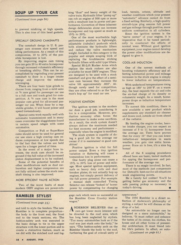
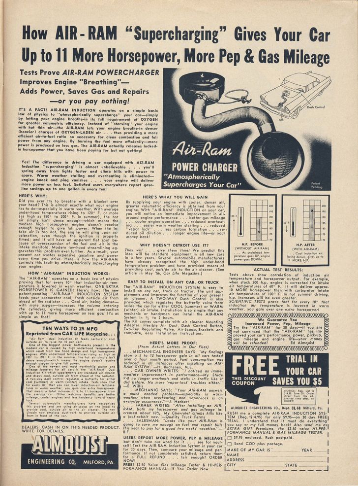
Found this Cool Air Induction "Soup up your car" article (partial) and advert in the Aug. 56 Issue of Car Life. I am liking the cable operated flapper valve that you could leave closed if the weather was real cold but open up on the highway in the summer/spring/fall.
Edited by 56D500boy 2018-02-21 9:06 PM
 (CarLifeAug1956_CoolAirInduction2_small.jpg) (CarLifeAug1956_CoolAirInduction2_small.jpg)
 (CarLifeAug1956_CoolAirInduction3_small.jpg) (CarLifeAug1956_CoolAirInduction3_small.jpg)
Attachments
----------------
CarLifeAug1956_CoolAirInduction2_small.jpg (232KB - 623 downloads)
CarLifeAug1956_CoolAirInduction3_small.jpg (223KB - 644 downloads)
|
|
| |
|
Expert 5K+
Posts: 7400
Location: northern germany | i have hundreds of old car mags, but never saw that before. great, thanks for sharing. please keep us updated about what you decide to do. i'd open it up. cold air will make it run smoother and more efficient.
Edited by 1960fury 2018-02-23 2:17 PM
|
|
| |
|
Expert 5K+
Posts: 5006
| that jeep hood almost has a 300C look to it. |
|
| |
|

Expert 5K+
Posts: 6500
Location: Newark, Texas (Fort Worth) | hmmm
 (my58wagsm2.jpg) (my58wagsm2.jpg)
Attachments
----------------
my58wagsm2.jpg (7KB - 645 downloads)
|
|
| |
|
Expert
Posts: 3967
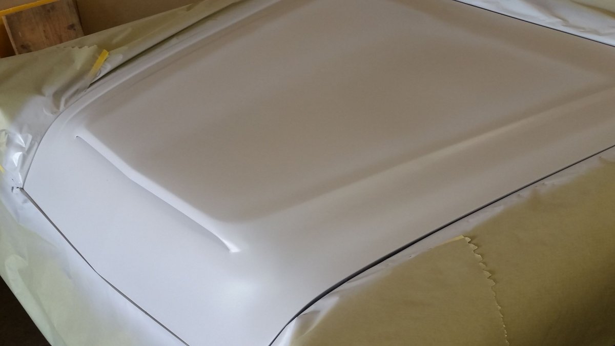
Location: DFW, TX | Here is a pic of it in primer.
 (20626411_1764356726926452_8919535165975749954_o.jpg) (20626411_1764356726926452_8919535165975749954_o.jpg)
Attachments
----------------
20626411_1764356726926452_8919535165975749954_o.jpg (57KB - 649 downloads)
|
|
| |
|
Expert
Posts: 3967
Location: DFW, TX | .
 (scoop.jpg) (scoop.jpg)
Attachments
----------------
scoop.jpg (248KB - 638 downloads)
|
|
| |
|
Expert 5K+
Posts: 9900
Location: Lower Mainland BC | Looking real good. Looks very factory, like they should have done it that way from the get-go. I like it.

|
|
| |
|
Expert 5K+
Posts: 6500
Location: Newark, Texas (Fort Worth) | Great work Danny! |
|
| |
|
Expert
Posts: 3967
Location: DFW, TX | Thank you for the compliments, guys. It was a lot of work and I'm ecstatic about how it turned out.
It would be cool if it were 'functional' as per the thread title, but I didn't want to hide the engine under a bunch of ducts and seals. If it was some kind of race car it would be worth it. |
|
| |
|
Expert 5K+
Posts: 9664
Location: So. Cal | If you cut the hole for it, it will at least provide cool air directly to your motor. Not as beneficial as low pressure induction, but better than sucking the air out from behind the radiator. |
|
| |
|
Expert
Posts: 3967
Location: DFW, TX | Eh, I really don't want a bunch of rain and dirt pouring on the engine as a tradeoff for a few degrees cooler air under the hood - especially since it still has that very restrictive side saddle air cleaner and WCFB.
I also don't want to create a high pressure area in the engine compartment that could screw up the cooling system airflow.
I've got a bigger cam on the shelf and a Hilborn stack injection I want to convert to EFI. I might consider doing something more with the hood then. |
|
| |
|
Expert 5K+
Posts: 9664
Location: So. Cal | I like those Hilborn injection systems, but I never came up with an air cleaner for them that I liked for everyday use. If you can incorporate an air cleaner into the base of the hood for them, that would be pretty cool.
Edited by Powerflite 2018-02-27 2:06 PM
|
|
| |
|
Expert 5K+
Posts: 9900
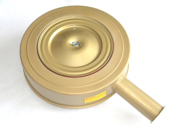
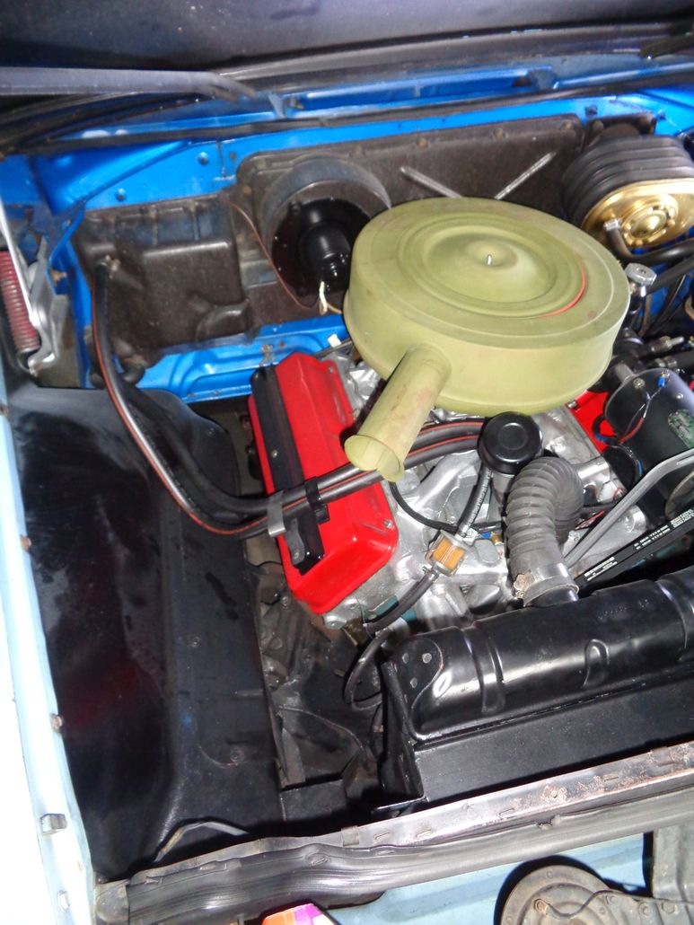
Location: Lower Mainland BC | I've always liked the look of the "Cadillac" style air cleaner. This one has been modified with two snorkels that car begging for connection to ducting through the rad support.

Vaguely like the Ford Fairlaine Thunderbolt intake
|
|
| |
|
Expert 5K+
Posts: 9900
Location: Lower Mainland BC | 56D500boy - 2018-03-07 12:17 PM
I've always liked the look of the "Cadillac" style air cleaner. This one has been modified with two snorkels that car begging for connection to ducting through the rad support.
Vaguely like the Ford Fairlaine Thunderbolt intake.
I found one of those Cadillac style air cleaners at the local Chevy/Ford Old Car Centre. Two diameters. The smallest was about 16" diameter and might clear my PS pump.
BUT then I realized that my battery is in the way of the possibility of twin ducts.
Using this as the idea:

What years have a single snorkle paper filter air cleaner with a 4 7/32" throat to fit on a WCFB 4 bbl carb?
Something like this on a 58 Plymouth suburban wagon?
Edited by 56D500boy 2018-03-11 2:41 PM
 (1958PlymouthSuburban_04_700.jpg) (1958PlymouthSuburban_04_700.jpg)
Attachments
----------------
1958PlymouthSuburban_04_700.jpg (71KB - 624 downloads)
|
|
| |
|
Expert
Posts: 3967
Location: DFW, TX | Two thoughts.
First, your stock '56 315 engine would get more than enough cool air from a single duct. I am sure two would satisfy your OCD though. 
Second, ducting from the core support bypasses the need for a 'functional' scoop on the hood.  |
|
| |
|
Expert 5K+
Posts: 9900
Location: Lower Mainland BC | 57burb - 2018-03-12 10:00 AM
Two thoughts.
First, your stock '56 315 engine would get more than enough cool air from a single duct. I am sure two would satisfy your OCD though.
Second, ducting from the core support bypasses the need for a 'functional' scoop on the hood. :bleh:
Agree with both comments (well, except the OCD insinuation )
With a single snorkel air cleaner, I could run the ducting to a new hole in the rad support along this pathway:
 (DForgies56D500EngineBayShowingPotentialPathForColdAirDuctingToRadSupport.jpg) (DForgies56D500EngineBayShowingPotentialPathForColdAirDuctingToRadSupport.jpg)
Attachments
----------------
DForgies56D500EngineBayShowingPotentialPathForColdAirDuctingToRadSupport.jpg (242KB - 697 downloads)
|
|
| |
|
Expert 5K+
Posts: 9900
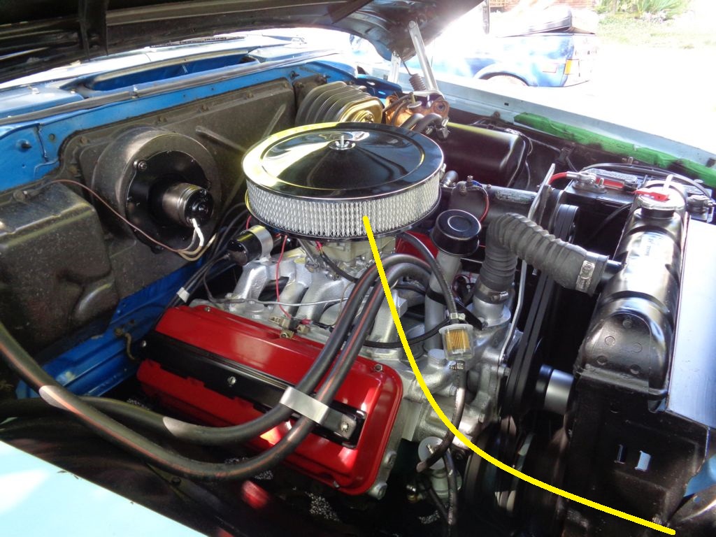
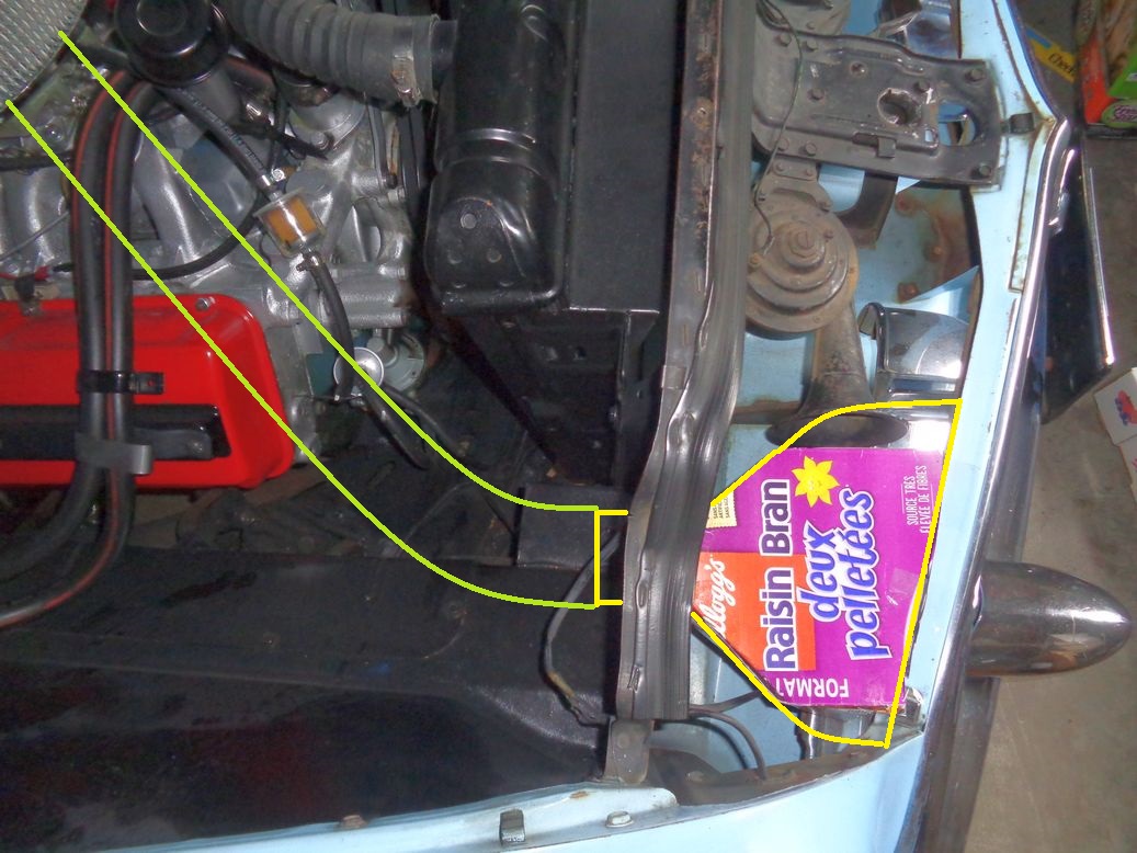
Location: Lower Mainland BC | 56D500boy - 2018-03-12 1:06 PM
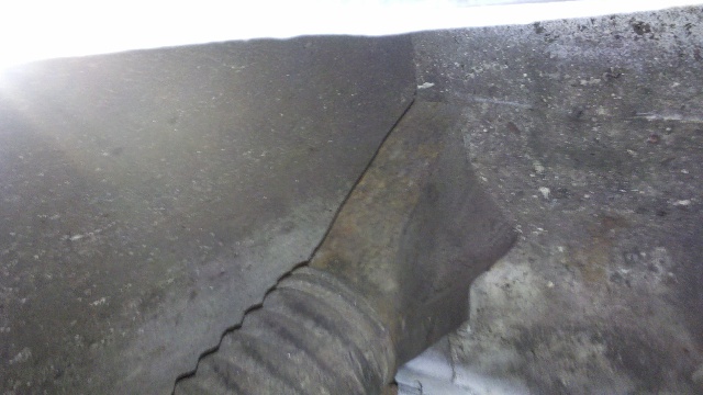
With a single snorkel air cleaner, I could run the ducting to a new hole in the rad support along this pathway:
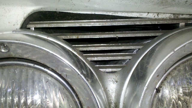
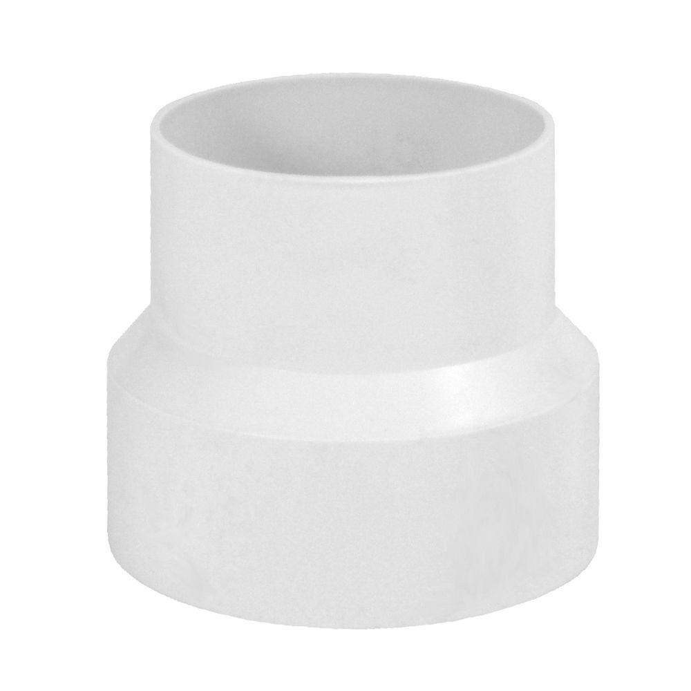
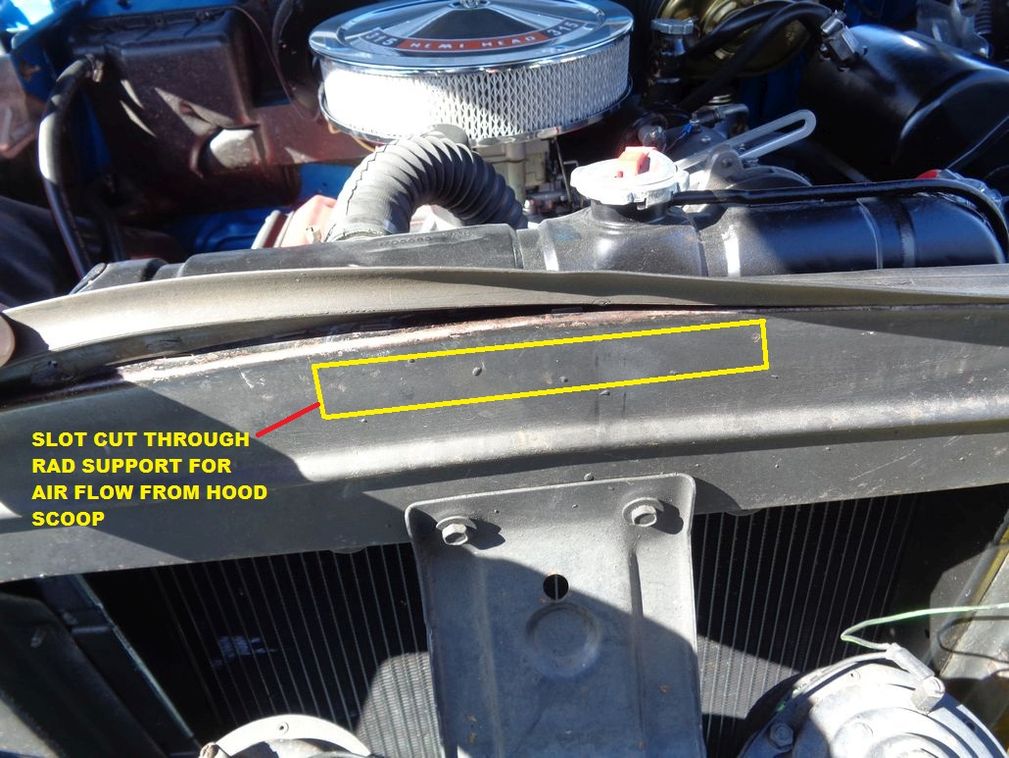
And then through the bulkhead and onto a scoop that would be fed from the grill area as illustrated below:
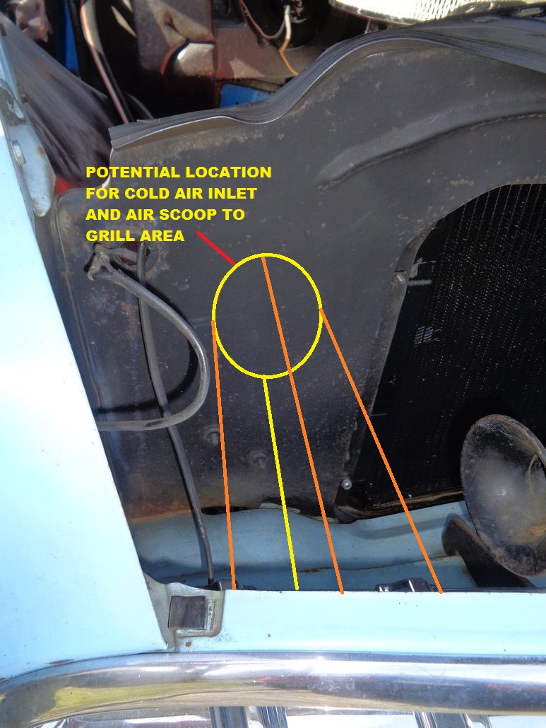 (56DodgeRadSupportBulkhead_Annotated.jpg) (56DodgeRadSupportBulkhead_Annotated.jpg)
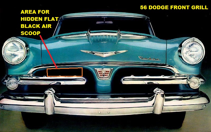 (56DodgeFrontGrill_AnnotedToShowPotentialLocationForHiddenAirScoop.jpg) (56DodgeFrontGrill_AnnotedToShowPotentialLocationForHiddenAirScoop.jpg)
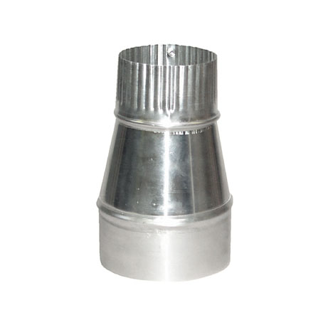 (4inchTo3inchReducer.jpg) (4inchTo3inchReducer.jpg)
 (PotentialBehindGrillInletBoot.jpg) (PotentialBehindGrillInletBoot.jpg)
Attachments
----------------
56DodgeRadSupportBulkhead_Annotated.jpg (211KB - 692 downloads)
56DodgeFrontGrill_AnnotedToShowPotentialLocationForHiddenAirScoop.jpg (162KB - 617 downloads)
4inchTo3inchReducer.jpg (24KB - 629 downloads)
PotentialBehindGrillInletBoot.jpg (38KB - 624 downloads)
|
|
| |
|
Expert 5K+
Posts: 7400
Location: northern germany | requires some fabrication but without a doubt i'd use the "opening" under the hood chrome and extend the entry under the hood (if theres enough room above the radiator) then fabricate an a/c housing with a large square funnel like inlet* that faces the hood cold air "channel". maybe the required gap between hood and a/c hsg could be sealed with foam, not easy but doable. that chrome thingy looks too tempting as an air grabber
* like air box model 14x3S here:
http://www.ramairbox.com/models.html
that square funnel you posted above, less favorable. try to avoid sudden transition from large to small (inlet to engine outlet) make it smooth, helps ramming the air.
Edited by 1960fury 2018-03-12 9:23 PM
 (14x3s.jpg) (14x3s.jpg)
Attachments
----------------
14x3s.jpg (2KB - 625 downloads)
|
|
| |
|
Expert 5K+
Posts: 7400
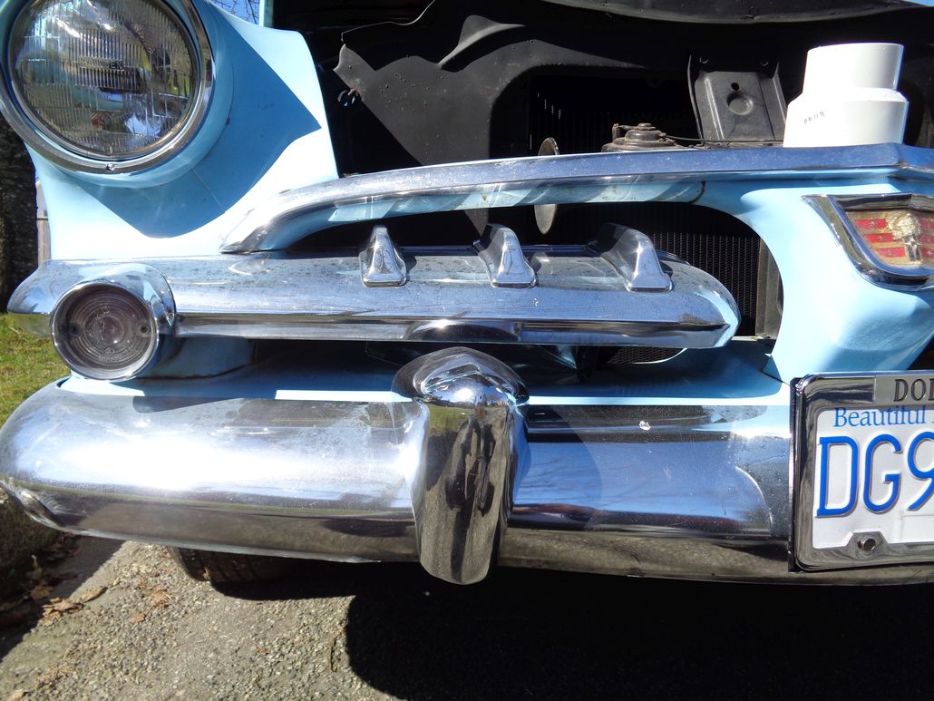
Location: northern germany | looking at the 56 again... when using the hood/chrome as a cold air inlet you got 2 options, one is aesthetically more pleasing but the opening would be a bit too small, if you cut the hood under the chrome not further than the teeth in the chrome, or slightly short. it would give the teeth a grill-like, factory original appearance. the other is to create a bigger opening, but not sure how it would look like with the teeth hanging in the air. |
|
| |
|
Expert 5K+
Posts: 9900
Location: Lower Mainland BC | 1960fury - 2018-03-12 9:14 PM
looking at the 56 again... when using the hood/chrome as a cold air inlet you got 2 options, one is aesthetically more pleasing but the opening would be a bit too small, if you cut the hood under the chrome not further than the teeth in the chrome, or slightly short. it would give the teeth a grill-like, factory original appearance. the other is to create a bigger opening, but not sure how it would look like with the teeth hanging in the air.
I had a look at the rad support this afternoon and it comes up tight to the hood obviously. To run the toothed factory "scoop" I would have to create a notch in the rad support. But I couldn't go too deep because of the rad top tank.
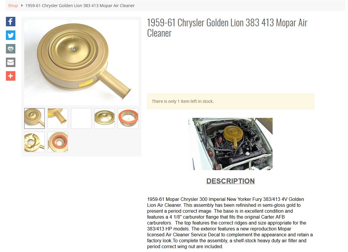
I think going through the bulkhead like you did would be a better way to go. Thanks also for the lead on "ram-air" boxes. The other way to go might be a 59-61 383 Air cleaner, if 4 1/8" for an AFB is really the same as 4 7/32" for a WCFB.
 (59-61GoldenLionAirCleaner.jpg) (59-61GoldenLionAirCleaner.jpg)
Attachments
----------------
59-61GoldenLionAirCleaner.jpg (174KB - 607 downloads)
|
|
| |
|
Expert 5K+
Posts: 7400
Location: northern germany | 56D500boy - 2018-03-12 9:31 PM
I had a look at the rad support this afternoon and it comes up tight to the hood obviously. To run the toothed factory "scoop" I would have to create a notch in the rad support. But I couldn't go too deep because of the rad top tank.
i see, but keep in mind that the cold air channel wouldn't have to be straight all the way, it could sneak along the inner hood towards the AC.
Edited by 1960fury 2018-03-12 10:01 PM
|
|
| |
|
Expert 5K+
Posts: 9900
Location: Lower Mainland BC | I am pursuing the 59-61 Golden Commando style air cleaner idea with the nice 3" diameter snorkel. Something like this one (but less pretty, and less expensive):
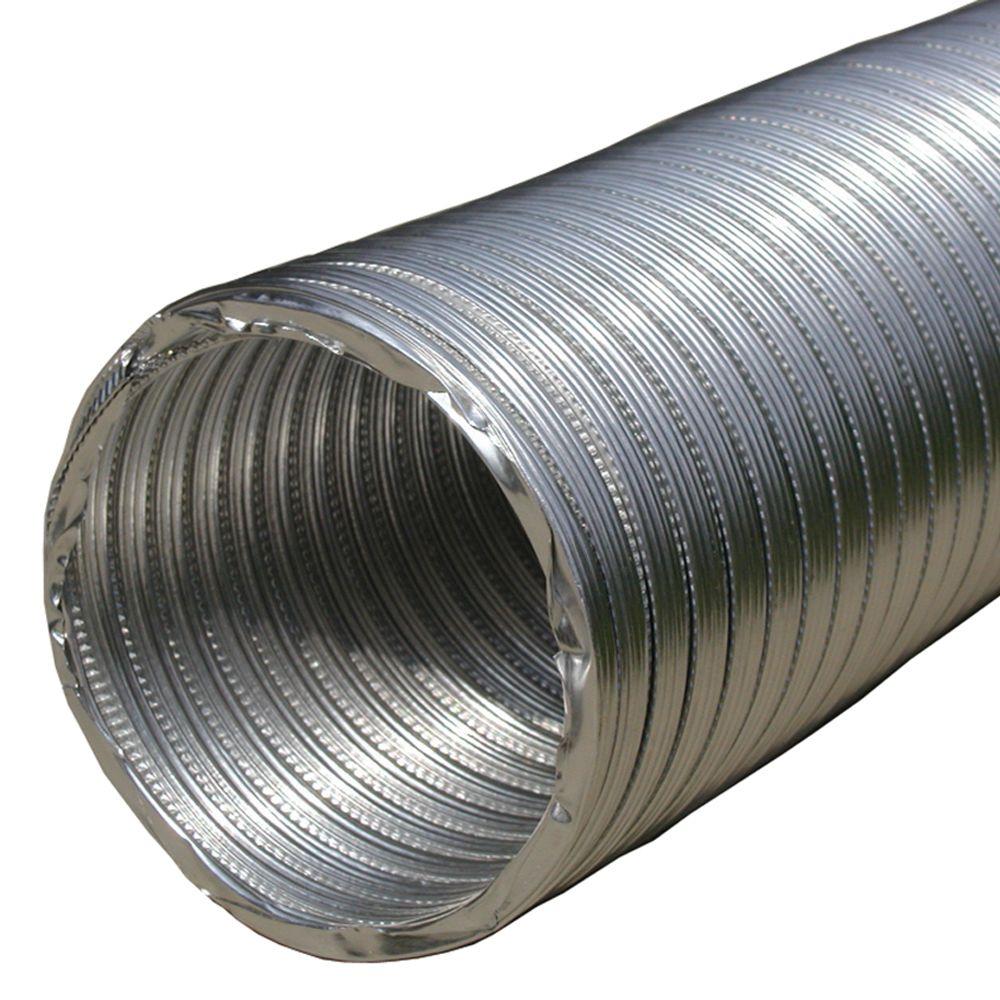
There would be 3" flexible ducting from the snorkel to the bulk head. Something like a piece of this flexible, expandable 3" aluminum ducting (8 ft for $9 at Home Depot):
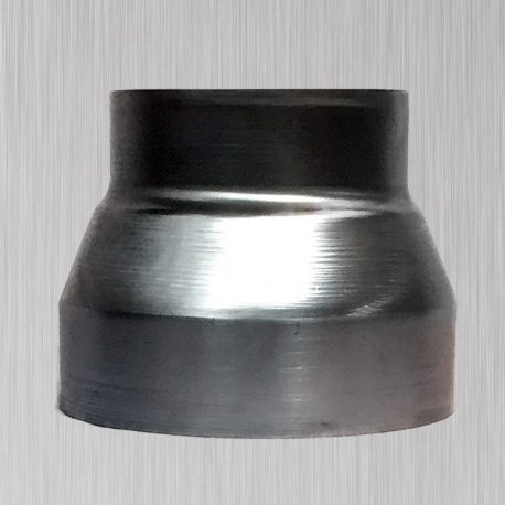
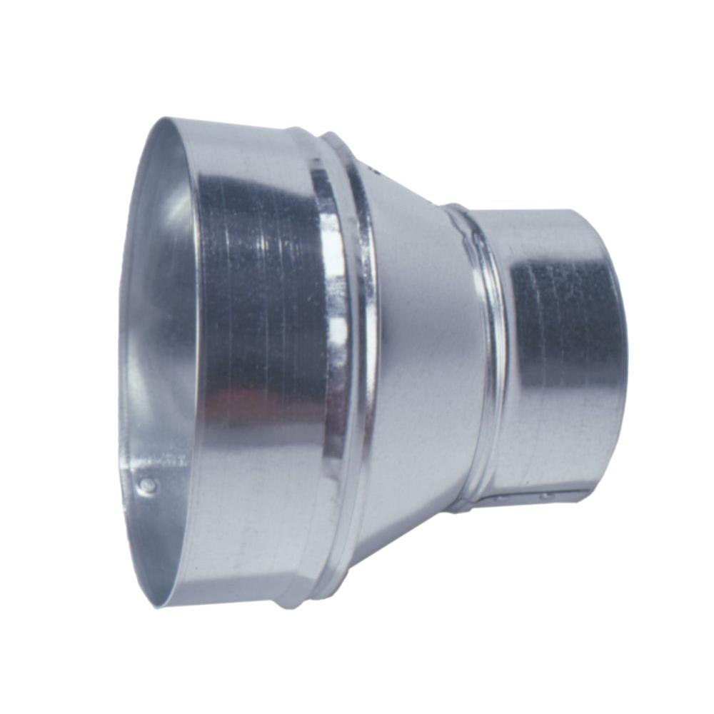
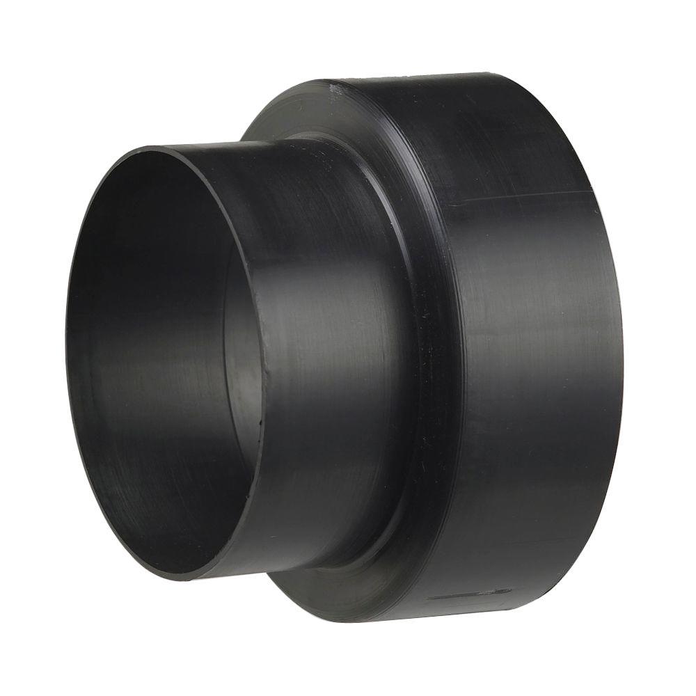
Through the bulkhead/rad support, I envision cutting a 3" hole and inserting a 3" to 4" reducer. I was looking for a nice spun aluminum 3" to 4" reducer to fit at the rad support/ bulkhead. I find them on line but not in person (so far).
The spun aluminum option (no price yet, I can't find a supplier):
The 26 gauge galvanized option (under $8 at Home Depot):
The polypropylene options (under $3 at Home Depot):
or
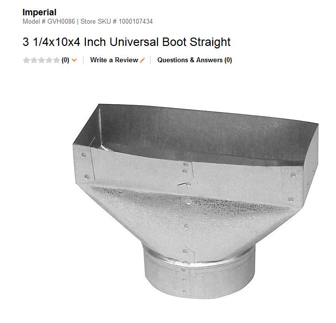
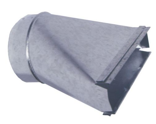
Still working on a prettier intake scoop (for behind the grill) besides the heating boot. Something like this 10" x 3.25" x 4 in (duct diameter) "Stack" boot (< $9 at Home Depot) only prettier and with 1/4" metal mesh to keep the squirrels and little kiddies out of the intake.
Edited by 56D500boy 2018-03-13 8:13 PM
 (10inchX3point25inchX4inchStackBoot.jpg) (10inchX3point25inchX4inchStackBoot.jpg)
Attachments
----------------
10inchX3point25inchX4inchStackBoot.jpg (13KB - 557 downloads)
|
|
| |
|
Expert 5K+
Posts: 7400
Location: northern germany | 56D500boy - 2018-03-13 8:09 PM
I am pursuing the 59-61 Golden Commando style air cleaner idea with the nice 3" diameter snorkel.
you can't find those on US build commandos. only canadian GCs had the snorkel type hsg. |
|
| |
|
Expert 5K+
Posts: 9900
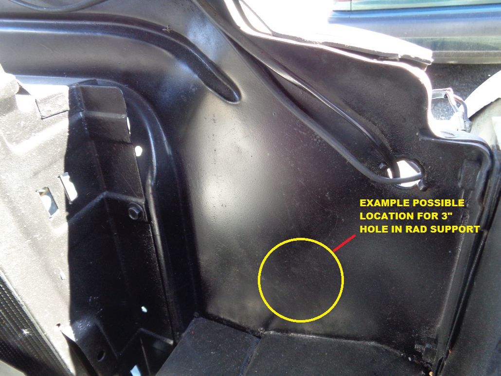
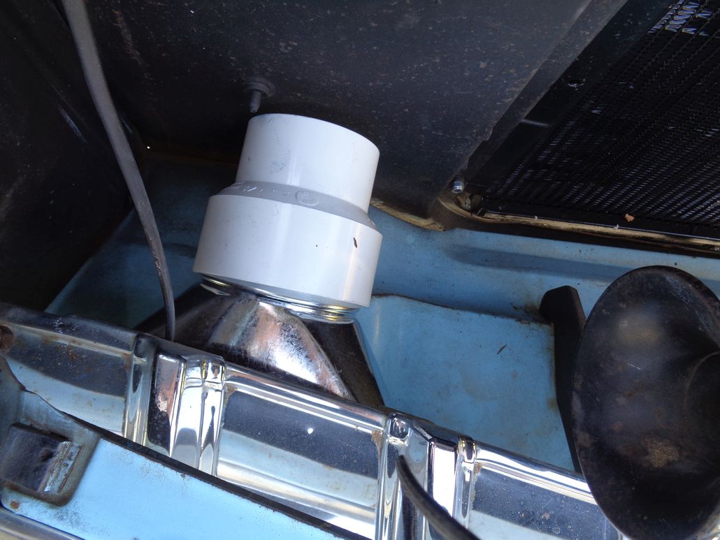
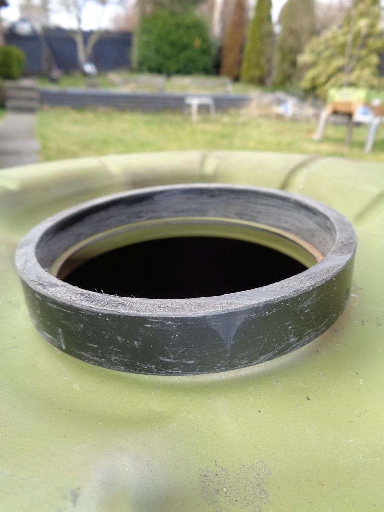
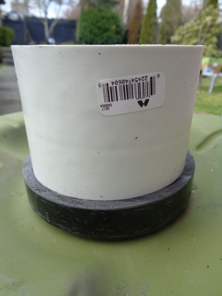
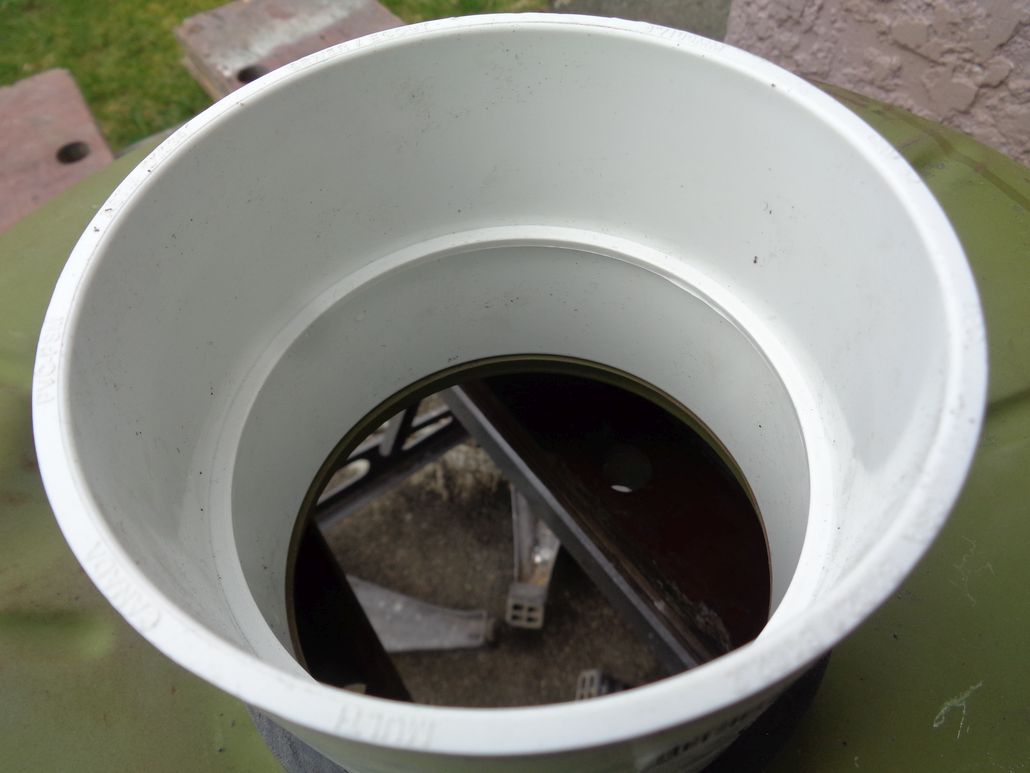
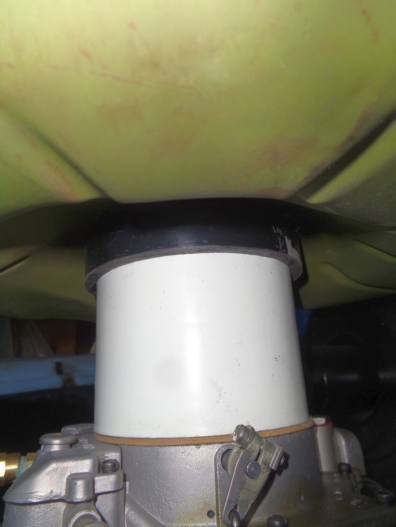
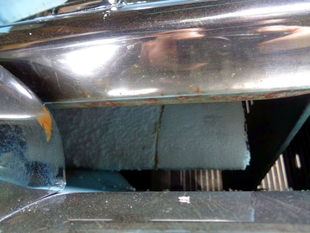
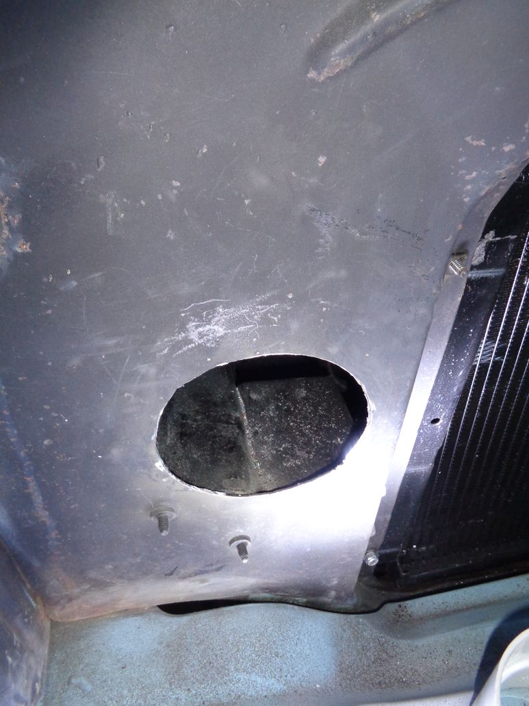
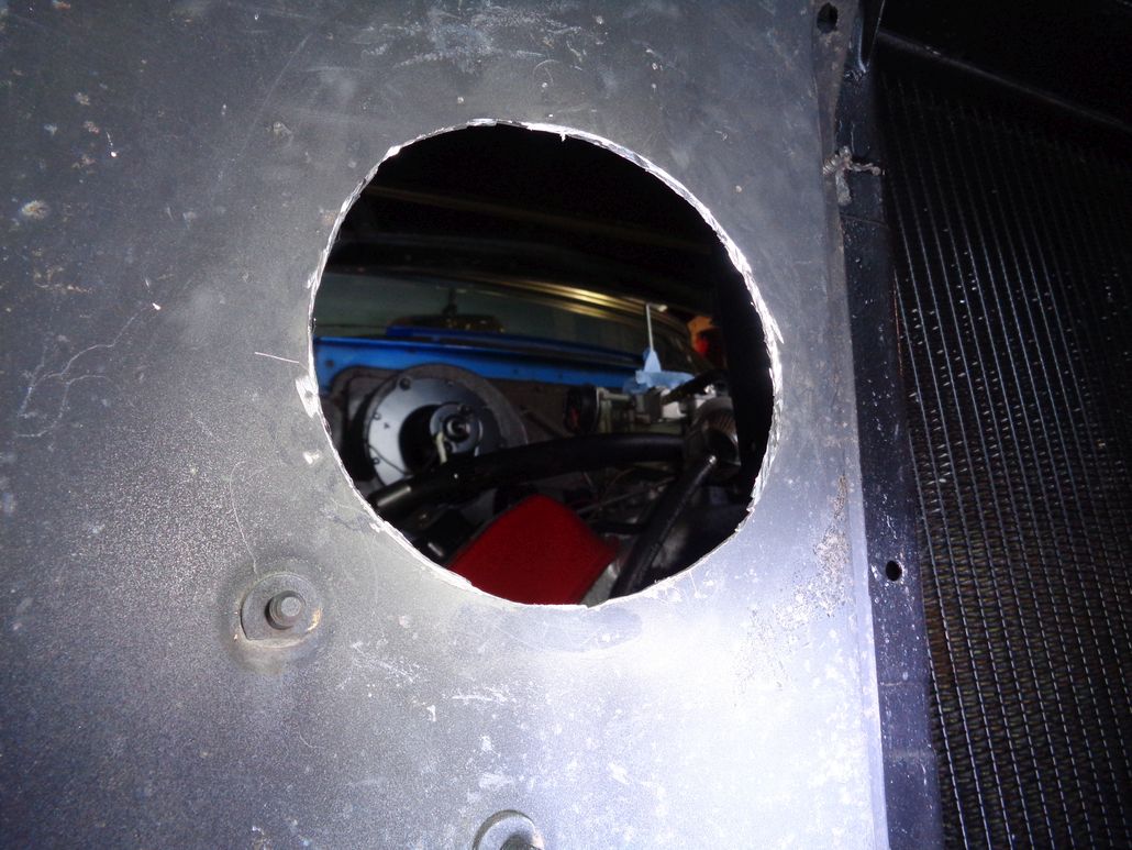
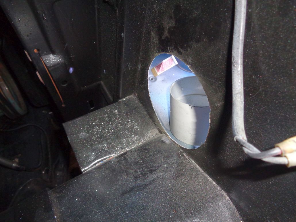
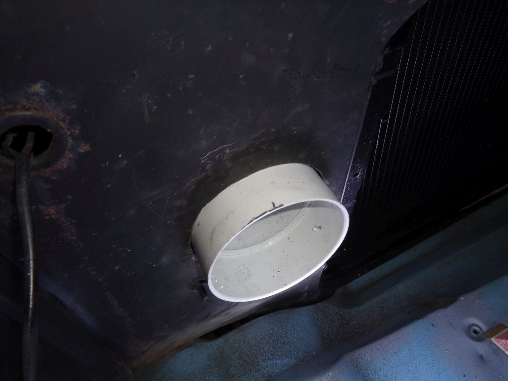
Location: Lower Mainland BC | I bought a plastic 4" to 3" reducer and a 4" x 3.25" x 10" Stack Boot yesterday to test out the possibility of going through the rad support/bulk head. There is plenty of room on the engine bay side for a 3" hole. On the grill side of the bulk head, there are two possibilities for the air scoop: above the grill bar and below the grill bar. I only trialed the below the grill bar possibility. In either case either the stack boot will have to be trimmed or an new purpose built scoop will have to fabricated. In either case, if the scoop is painted flat black it will never be seen by most people. See below:
 (56DodgeRadSupportDuctOption_0.jpg) (56DodgeRadSupportDuctOption_0.jpg)
 (56DodgeRadSupportDuctOption_1.jpg) (56DodgeRadSupportDuctOption_1.jpg)
 (56DodgeRadSupportDuctOption_2.jpg) (56DodgeRadSupportDuctOption_2.jpg)
 (56DodgeRadSupportDuctOption_3.jpg) (56DodgeRadSupportDuctOption_3.jpg)
 (56DodgeRadSupportDuctOption_4.jpg) (56DodgeRadSupportDuctOption_4.jpg)
 (56DodgeRadSupportDuctOption_5.jpg) (56DodgeRadSupportDuctOption_5.jpg)
Attachments
----------------
56DodgeRadSupportDuctOption_0.jpg (215KB - 570 downloads)
56DodgeRadSupportDuctOption_1.jpg (155KB - 569 downloads)
56DodgeRadSupportDuctOption_2.jpg (160KB - 581 downloads)
56DodgeRadSupportDuctOption_3.jpg (151KB - 561 downloads)
56DodgeRadSupportDuctOption_4.jpg (146KB - 584 downloads)
56DodgeRadSupportDuctOption_5.jpg (126KB - 572 downloads)
|
|
| |
|
Expert 5K+
Posts: 9900
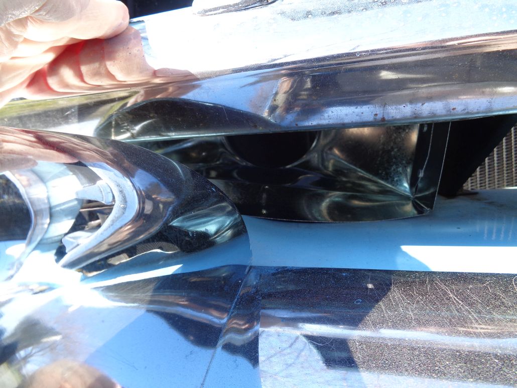
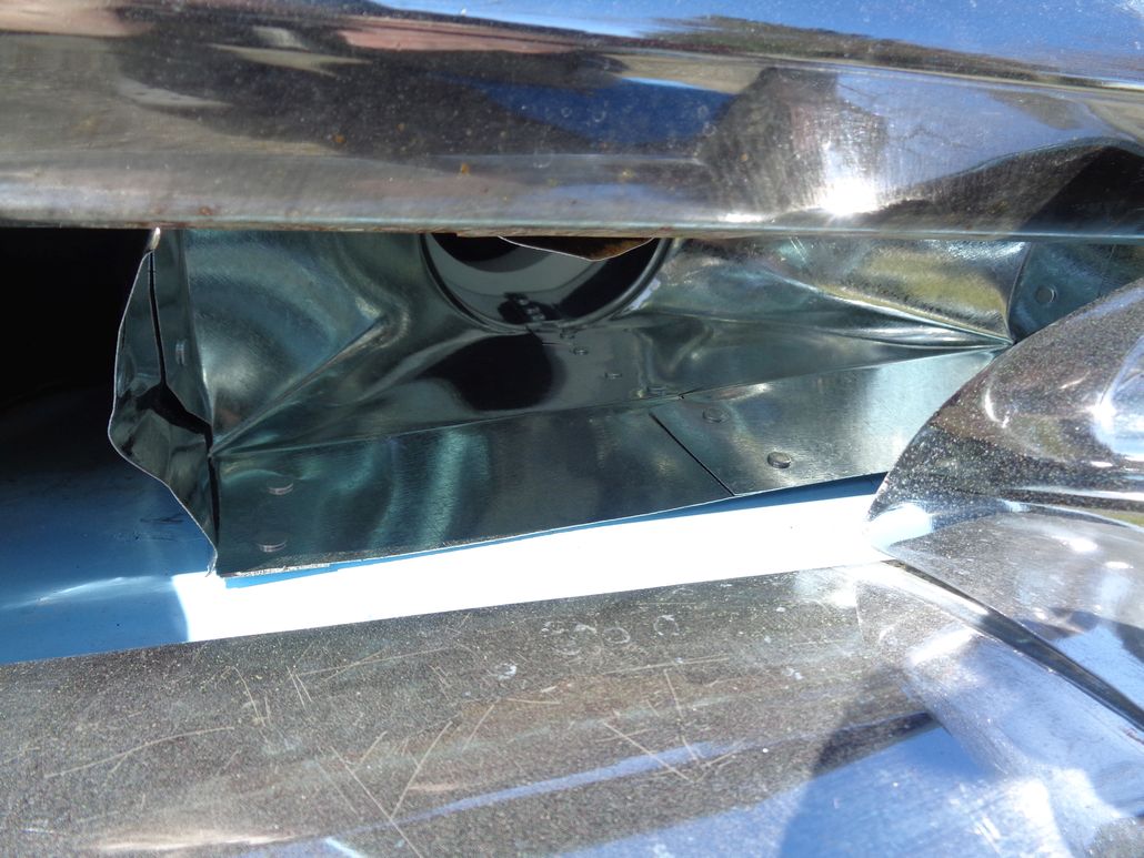
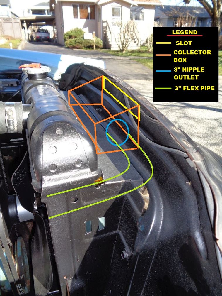
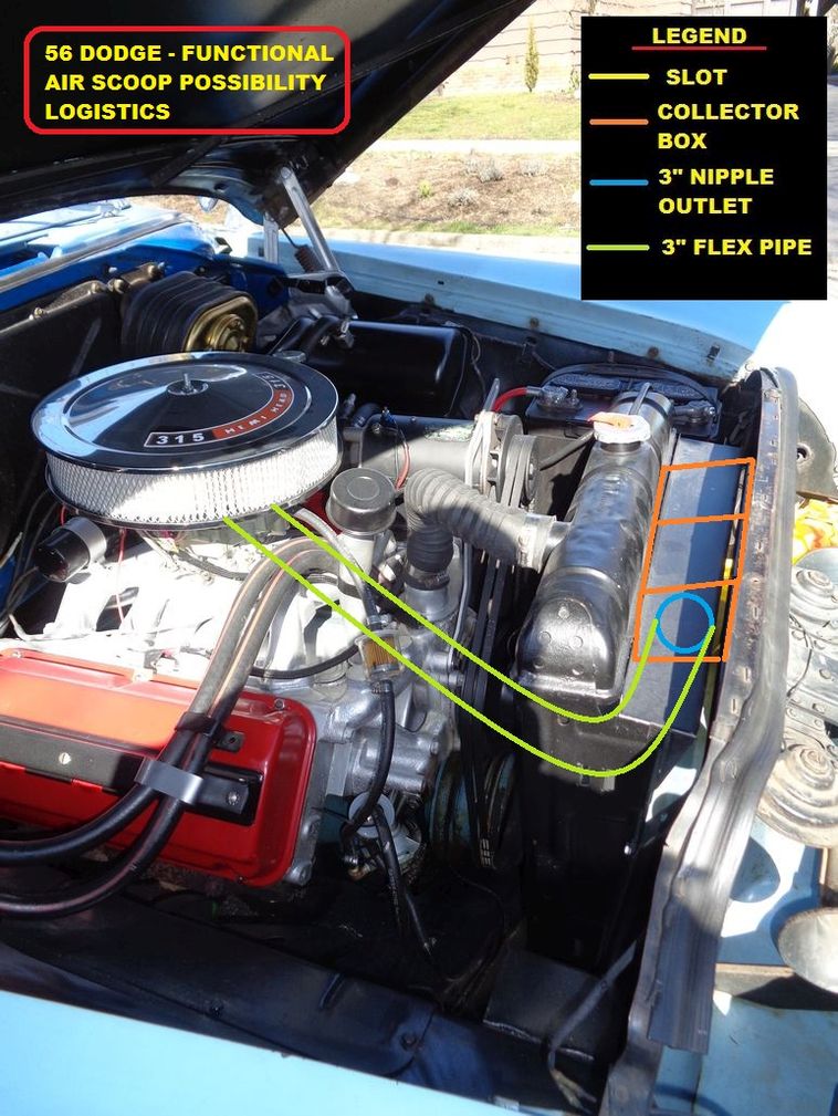
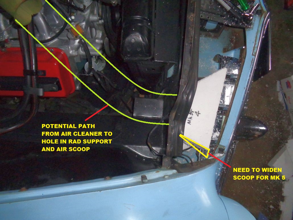
Location: Lower Mainland BC | While I was out playing with the behind-the-grill scoop option discussed above, I did some further thinking about activating that OE fake air scoop, as per the original purpose of this thread. IF I accept that the rad support would have to be cut to create an air path, it becomes a possibility. I would envision:
1. A slot in the hood behind the fake hood scoop in the grill ornament.
2. A duct of some form (plastic/fibreglas) attached to the underside of the hood running from the new hood opening and terminating just before the rad support. Initially mocked-up with cardboard and then made with ABS or perhaps aluminum or ??
3. A slot in the rad support
4. A collector box (plastic or fibreglas) on the engine side of the rad support terminating with a 3" nipple to attach 3" flex hose leading to a snorkel air cleaner
5. A snorkel air cleaner with a 3" snorkel, no wider than 16" (as per the OE oil bath air cleaner) - some ball peen hammer work might be needed.
Probably more work than the 3" round hole through the rad support option but "prettier" (maybe )
See annotated photos below.
Edited by 56D500boy 2018-03-16 4:01 PM
 (56DodgeWorkingHoodScoopPossibity_1.jpg) (56DodgeWorkingHoodScoopPossibity_1.jpg)
 (56DodgeWorkingHoodScoopPossibity_2.jpg) (56DodgeWorkingHoodScoopPossibity_2.jpg)
 (56DodgeWorkingHoodScoopPossibity_3.jpg) (56DodgeWorkingHoodScoopPossibity_3.jpg)
 (56DodgeWorkingHoodScoopPossibity_4.jpg) (56DodgeWorkingHoodScoopPossibity_4.jpg)
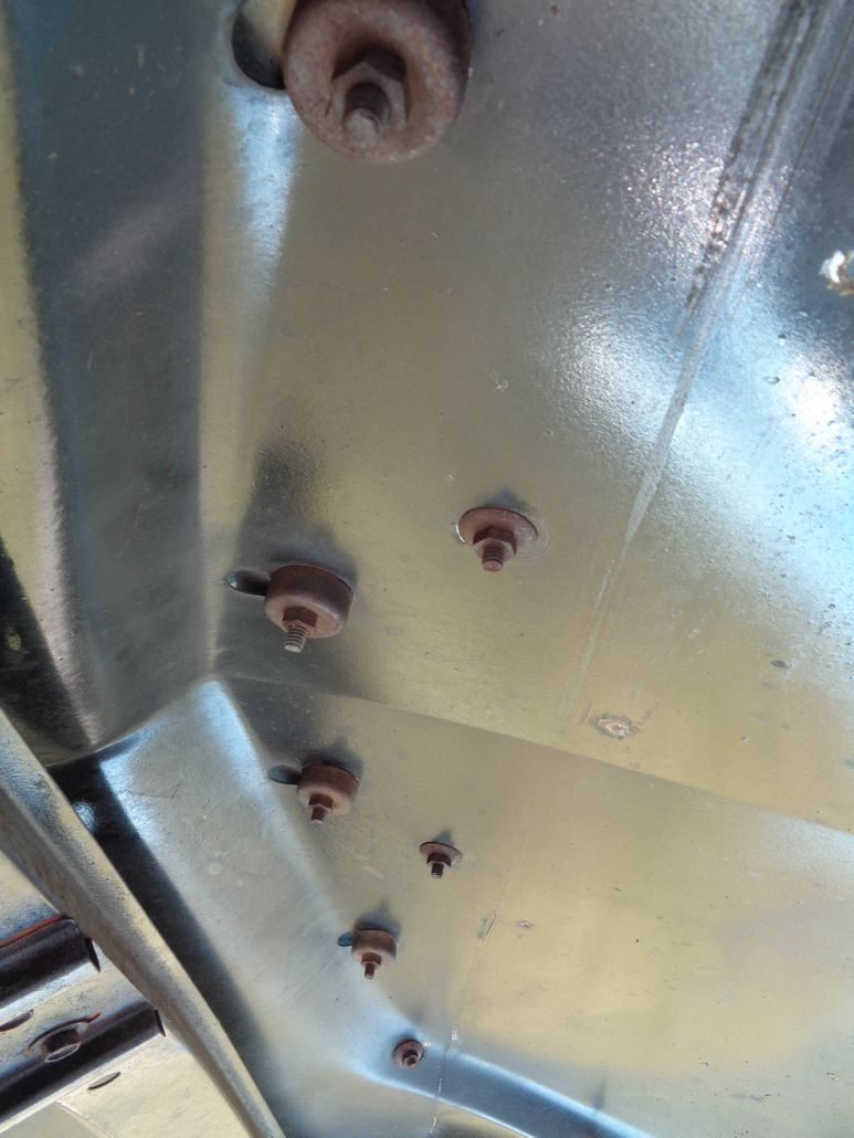 (UnderSideOf56DodgeHood.jpg) (UnderSideOf56DodgeHood.jpg)
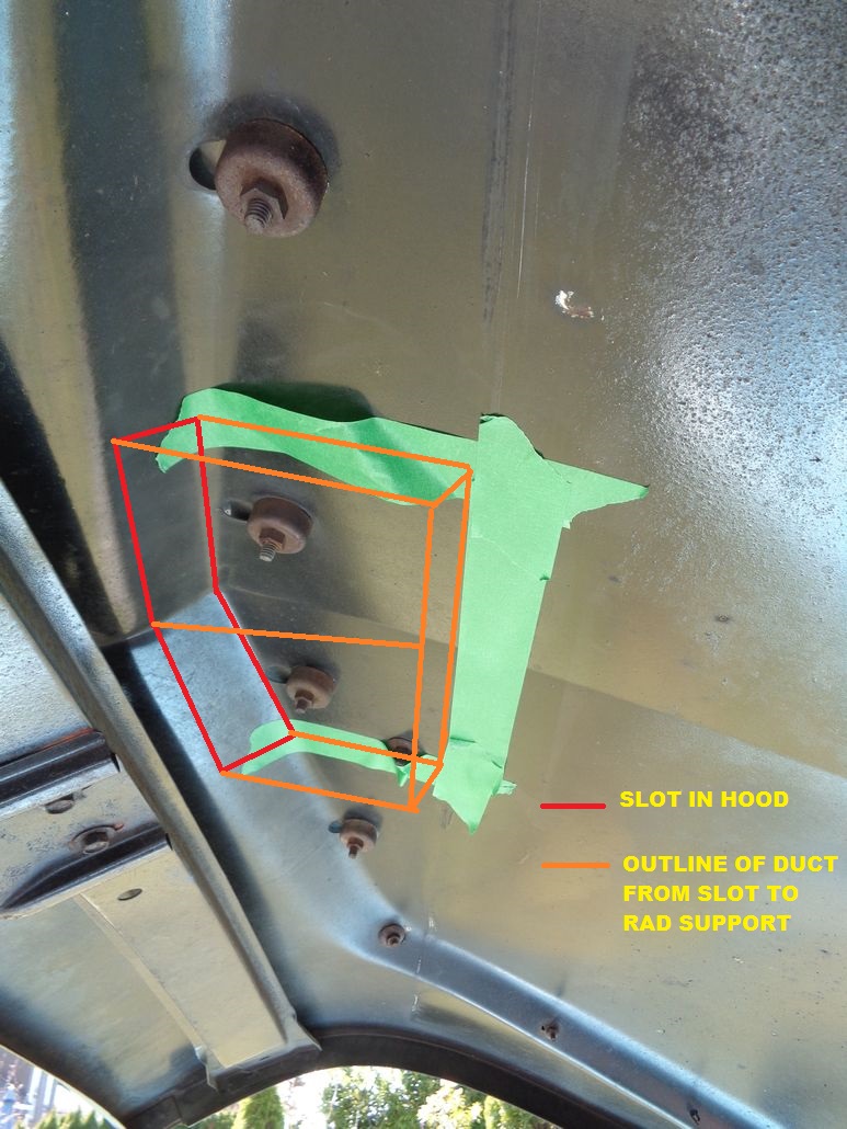 (UnderSideOf56DodgeHoodShowingAreaForSlotAndDuct_1.jpg) (UnderSideOf56DodgeHoodShowingAreaForSlotAndDuct_1.jpg)
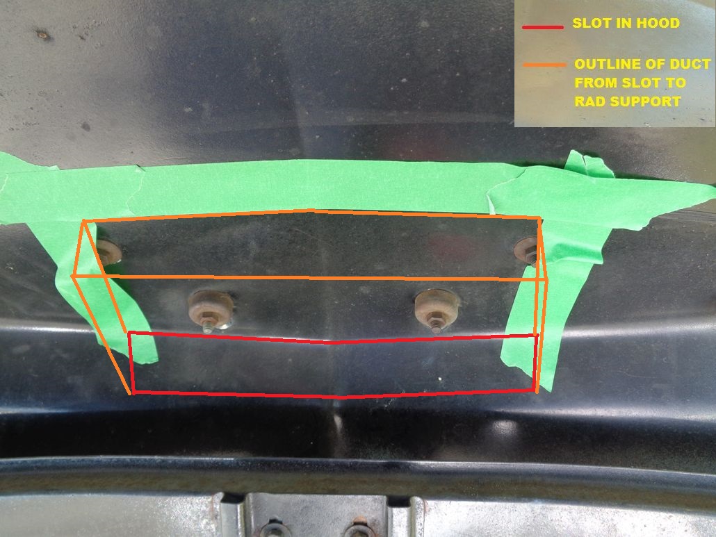 (UnderSideOf56DodgeHoodShowingAreaForSlotAndDuct_2.jpg) (UnderSideOf56DodgeHoodShowingAreaForSlotAndDuct_2.jpg)
Attachments
----------------
56DodgeWorkingHoodScoopPossibity_1.jpg (198KB - 567 downloads)
56DodgeWorkingHoodScoopPossibity_2.jpg (154KB - 577 downloads)
56DodgeWorkingHoodScoopPossibity_3.jpg (170KB - 579 downloads)
56DodgeWorkingHoodScoopPossibity_4.jpg (168KB - 574 downloads)
UnderSideOf56DodgeHood.jpg (109KB - 559 downloads)
UnderSideOf56DodgeHoodShowingAreaForSlotAndDuct_1.jpg (221KB - 567 downloads)
UnderSideOf56DodgeHoodShowingAreaForSlotAndDuct_2.jpg (210KB - 562 downloads)
|
|
| |
|
Expert 5K+
Posts: 7400
Location: northern germany | nice, i like your technical threads with all the pictures and drawings, etc.
that air box behind the hood inlet with a 90° bend (wall) directly after the opening would make it a cold air system, not a ram air system. is there really no room above the rad? |
|
| |
|
Regular
Posts: 65
| You could also use an air cleaner housing from a 5.0 Foxbody, they have dual outlets and the pipes go into the fender wells. Be easy enough to do for a Forward Look car of any year - save you from hacking up your nice steel. |
|
| |
|
Expert 5K+
Posts: 9900
Location: Lower Mainland BC | 1960fury - 2018-03-16 7:06 PM
nice, i like your technical threads with all the pictures and drawings, etc.
that air box behind the hood inlet with a 90° bend (wall) directly after the opening would make it a cold air system, not a ram air system. is there really no room above the rad?
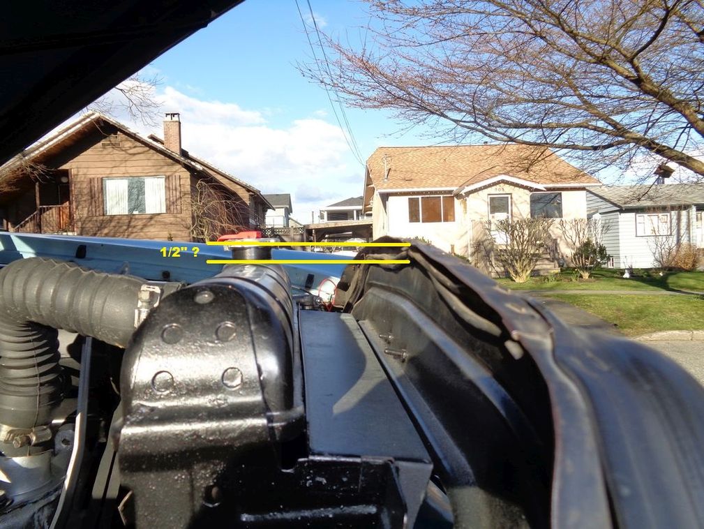
Agree about the lack of rack air with using the hoop "scoop" option. There is NO ROOM above the rad. Well maybe 1/2". Plus the rad cap, etc. is kind of in the way. Possible but not easy.
Edited by 56D500boy 2018-03-16 10:53 PM
 (ClearanceAboveRaditorToRadSupport.jpg) (ClearanceAboveRaditorToRadSupport.jpg)
Attachments
----------------
ClearanceAboveRaditorToRadSupport.jpg (179KB - 581 downloads)
|
|
| |
|
Expert 5K+
Posts: 9900
Location: Lower Mainland BC | 56RatKing - 2018-03-16 7:11 PM
You could also use an air cleaner housing from a 5.0 Foxbody, they have dual outlets and the pipes go into the fender wells. Be easy enough to do for a Forward Look car of any year - save you from hacking up your nice steel.
I am trying to achieve a bit of ram air not just cold air so that Fomoco aircleaner would NOT work for me. Or any Mopar dual snorkel air cleaner for that matter.
I "lucked" out and won an auction for a less than pretty 59-61 383/413 single snorkel air cleaner that should work with the through the rad support, behind the grill, air scoop option. The air cleaner was less than 1/5th of the very nice gold Golden Commando 383/413 air cleaner that I posted a photo of earlier. This one needs some work but that is fine. I need to paint it D500 hemi red (I have the official paint) anyway and I won't feel bad if I have to bash the bottom a bit to get the clearances for the fuel filter and the carb choke.
The pretty $299 one that was too nice and too much money:
https://musclecaraircleaners.com/products/1959-61-chrysler-golden-li...
The one I bought today:
https://www.ebay.ca/itm/292477495997?ul_noapp=true&autorefresh=true

Edited by 56D500boy 2018-03-16 11:04 PM
|
|
| |
|
Expert 5K+
Posts: 7400
Location: northern germany | just saw the wheeler dealer episode with the 53 firedome, they said the hood chrome is a cold air inlet too. very nice.
https://www.youtube.com/watch?v=s3ju7ve84dU&t=28s
Edited by 1960fury 2018-03-20 2:49 PM
|
|
| |
|
Expert 5K+
Posts: 9900
Location: Lower Mainland BC |
I could see that that might be possible because the 53 Desoto scoop is so high up on the hood and it might be behind the rad support gasket.
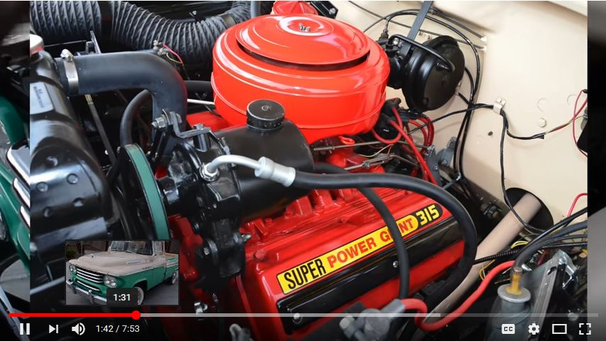
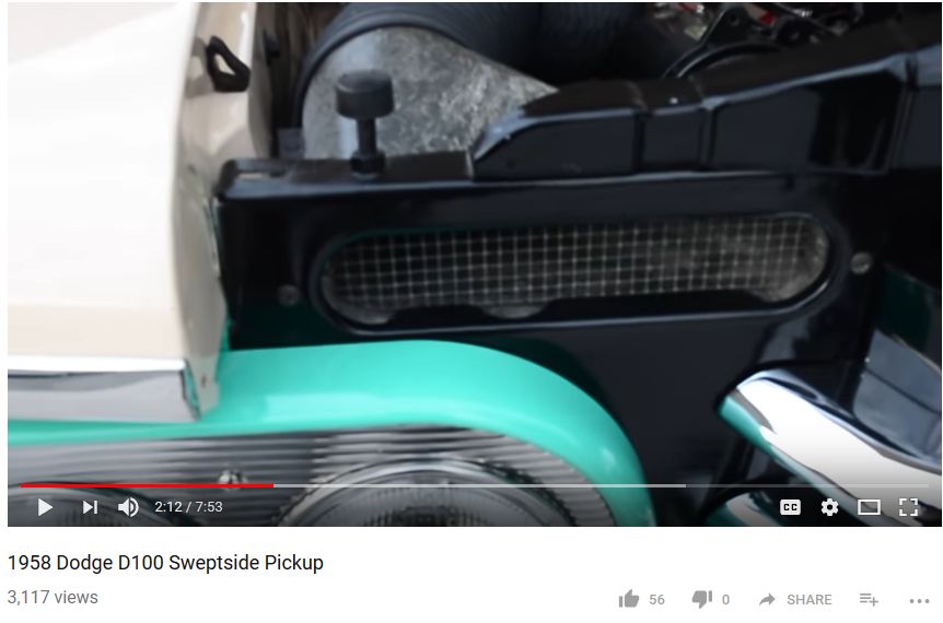
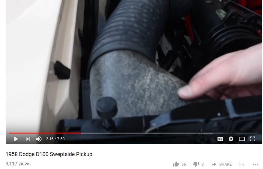
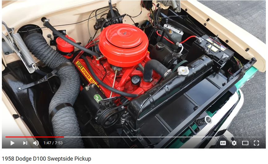
After I watched that video, I ended up watching a 1958 Dodge D100 Sweptside 315 Power Giant Hemi video that had cold air induction!! Factory screened slot in the rad support and factory fiberglas scoop. On the down side, they directed the air into the truck cab for ventilation, not to the engine for engine efficiency. Close but no cigars. But it does make me think.
https://www.youtube.com/watch?v=mDdofzpa7f0
Edited by 56D500boy 2018-03-20 4:59 PM
 (315PowerGiantInA1958DodgeSweptSidePickup.jpg) (315PowerGiantInA1958DodgeSweptSidePickup.jpg)
 (1958DodgeSweptsideColdAirInductionIntakeforAC.jpg) (1958DodgeSweptsideColdAirInductionIntakeforAC.jpg)
 (1958DodgeSweptsideColdAirInductionIntakeforAC_2.jpg) (1958DodgeSweptsideColdAirInductionIntakeforAC_2.jpg)
 (1958DodgeSweptsideColdAirInductionIntakeforAC_3.jpg) (1958DodgeSweptsideColdAirInductionIntakeforAC_3.jpg)
Attachments
----------------
315PowerGiantInA1958DodgeSweptSidePickup.jpg (83KB - 566 downloads)
1958DodgeSweptsideColdAirInductionIntakeforAC.jpg (48KB - 565 downloads)
1958DodgeSweptsideColdAirInductionIntakeforAC_2.jpg (39KB - 573 downloads)
1958DodgeSweptsideColdAirInductionIntakeforAC_3.jpg (95KB - 571 downloads)
|
|
| |
|
Expert 5K+
Posts: 9900
Location: Lower Mainland BC |
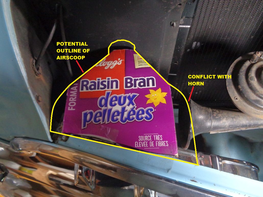
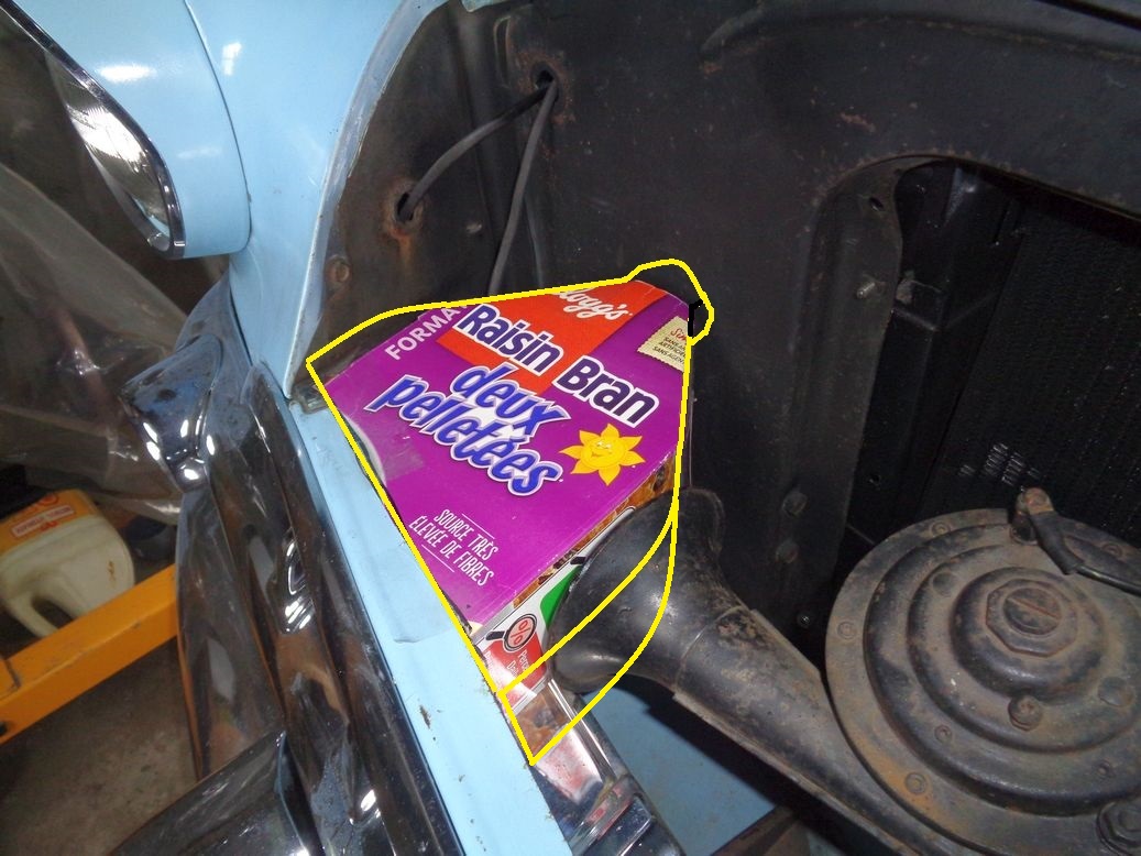
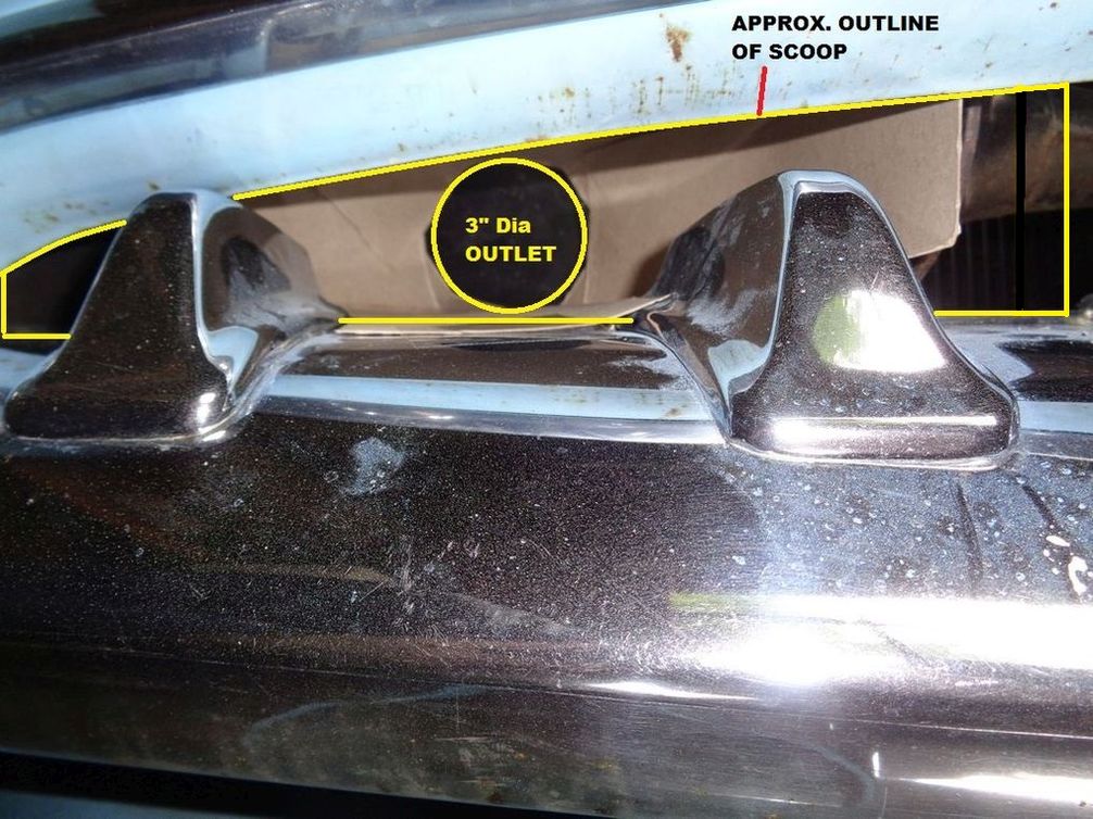
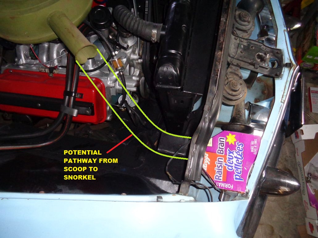
Inspired (?!) by that stock Sweptside fibreglass air scoop and after watching some videos about making a fiberglass scoop over a sculpted foam core, I have bought some supplies to make such a scoop. This afternoon, I found yet another empty Raisin Bran box to cut up to create a rough mock-up of scoop that would sit behind the right grill bar and lead to a 3" hole in the rad support which would then lead on to the snorkel on 59 Chrysler 383/413 air cleaner (which arrived today at my US mail drop - pick it up tomorrow). There will be conflicts: I would like the scoop to be bigger than the Raisin Bran box and that would mean that the right horn will have to go or otherwise be turned or (???).
Here's a peak at the current concept:
 (ScoopGrillHornAndRadSupport_Annotated.jpg) (ScoopGrillHornAndRadSupport_Annotated.jpg)
 (ScoopAndHorn_Annotated.jpg) (ScoopAndHorn_Annotated.jpg)
 (BasicBehindTheGrillAirScoop_Annotated.jpg) (BasicBehindTheGrillAirScoop_Annotated.jpg)
 (BasicScoopToAirCleanerFlow_Annotated.jpg) (BasicScoopToAirCleanerFlow_Annotated.jpg)
Attachments
----------------
ScoopGrillHornAndRadSupport_Annotated.jpg (224KB - 559 downloads)
ScoopAndHorn_Annotated.jpg (217KB - 568 downloads)
BasicBehindTheGrillAirScoop_Annotated.jpg (168KB - 548 downloads)
BasicScoopToAirCleanerFlow_Annotated.jpg (229KB - 536 downloads)
|
|
| |
|
Expert 5K+
Posts: 9664
Location: So. Cal | As shown, you are going to lose most of the benefit from the air drag inside that hose. Is there any way to increase it's diameter dramatically? In general, you want to keep the inside area the same as the inside area that you start with, except that it can decrease a little as the drag slows it down. The slow decrease of area will keep the speed up so you won't lose your dynamic pressure differential. You will lose a lot of air speed once it hits the air filter, but you want to keep the speed up until it reaches that point at least. |
|
| |
|
Expert 5K+
Posts: 9900
Location: Lower Mainland BC | Thanks for the comments Nathan.
I haven't got the aircleaner in my hands yet. I will be going to Point Roberts WA tomorrow to pick it up. I am told that the diameter of the snorkel is 3":
I could go 4" diameter on the scoop outlet and through the rad support and then use 4" flex hose. But at the end, I have to go down to 3" unless there is enough height on the side of the aircleaner to cut off the 3" snorkel and get a 4" welded on.
Alternatively, I could go 3" I.D. hard pipe from a 3" scoop outlet @ the rad support and then over to the air cleaner with only a bit of 3" flex at the end.
|
|
| |
|
Expert 5K+
Posts: 9900
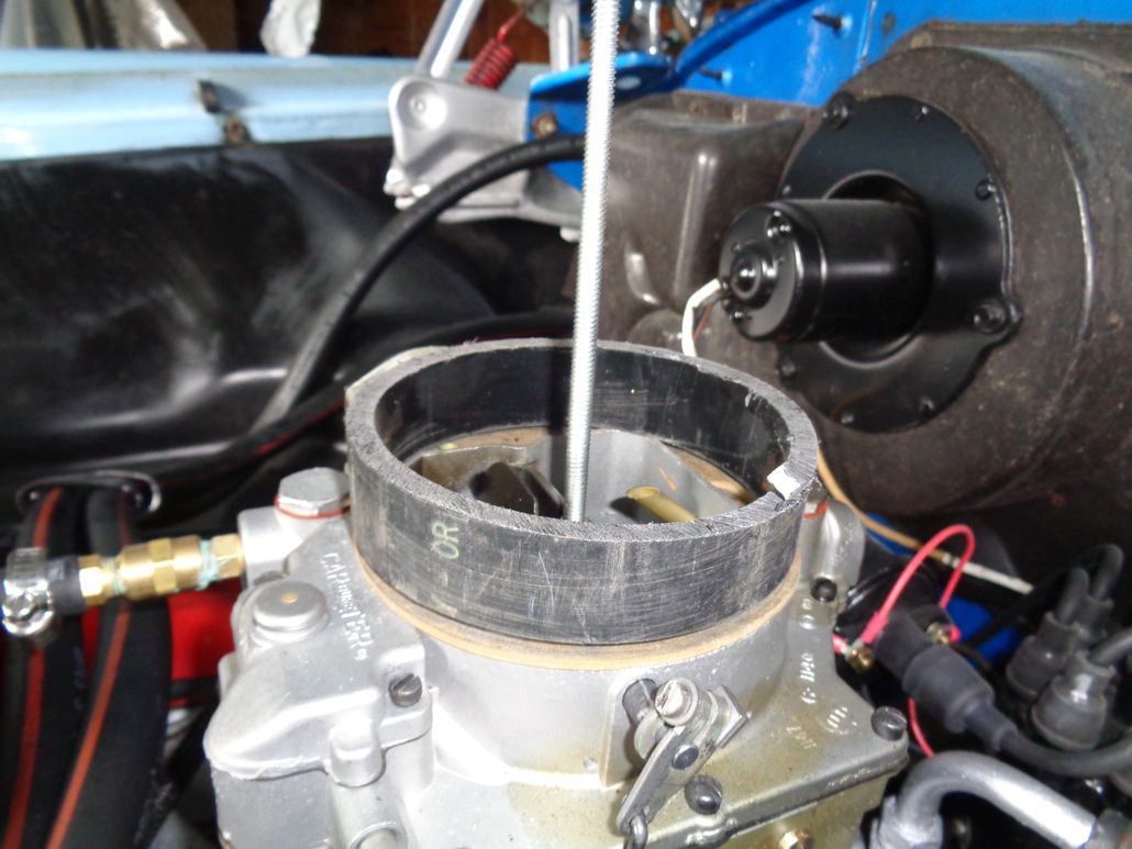
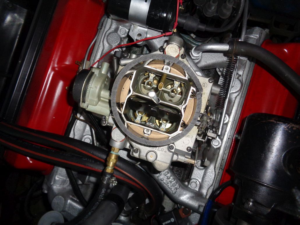
Location: Lower Mainland BC | 56D500boy - 2018-03-23 9:32 PM
I haven't got the aircleaner in my hands yet. I will be going to Point Roberts WA tomorrow to pick it up. I am told that the diameter of the snorkel is 3"
:)
Picked up the eBay $55 Golden Lion air cleaner today. It's going to work. I am going to have to beat it a bit with a ball peen hammer to get some clearances for the choke, carb fuel line and the PS pump but I was expecting that. At least I didn't buy the $299 gold air cleaner, that would have hurt to hit with a hammer. This one, no problemo.
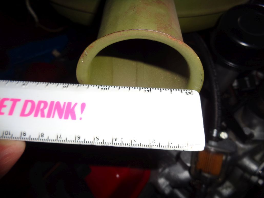
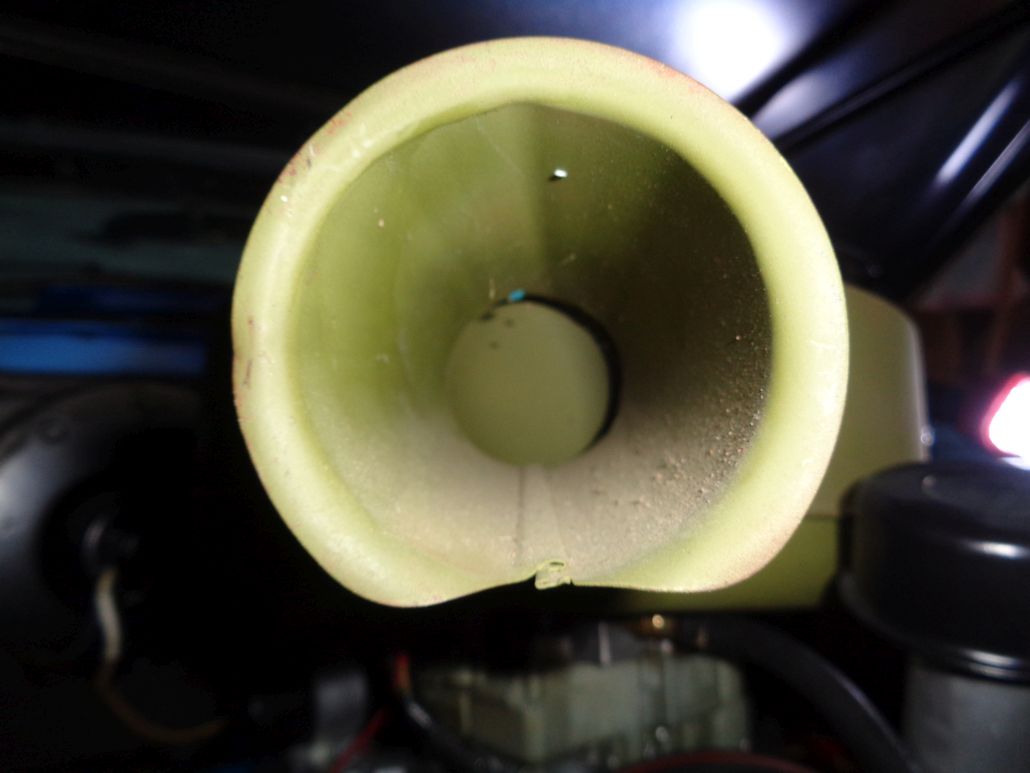
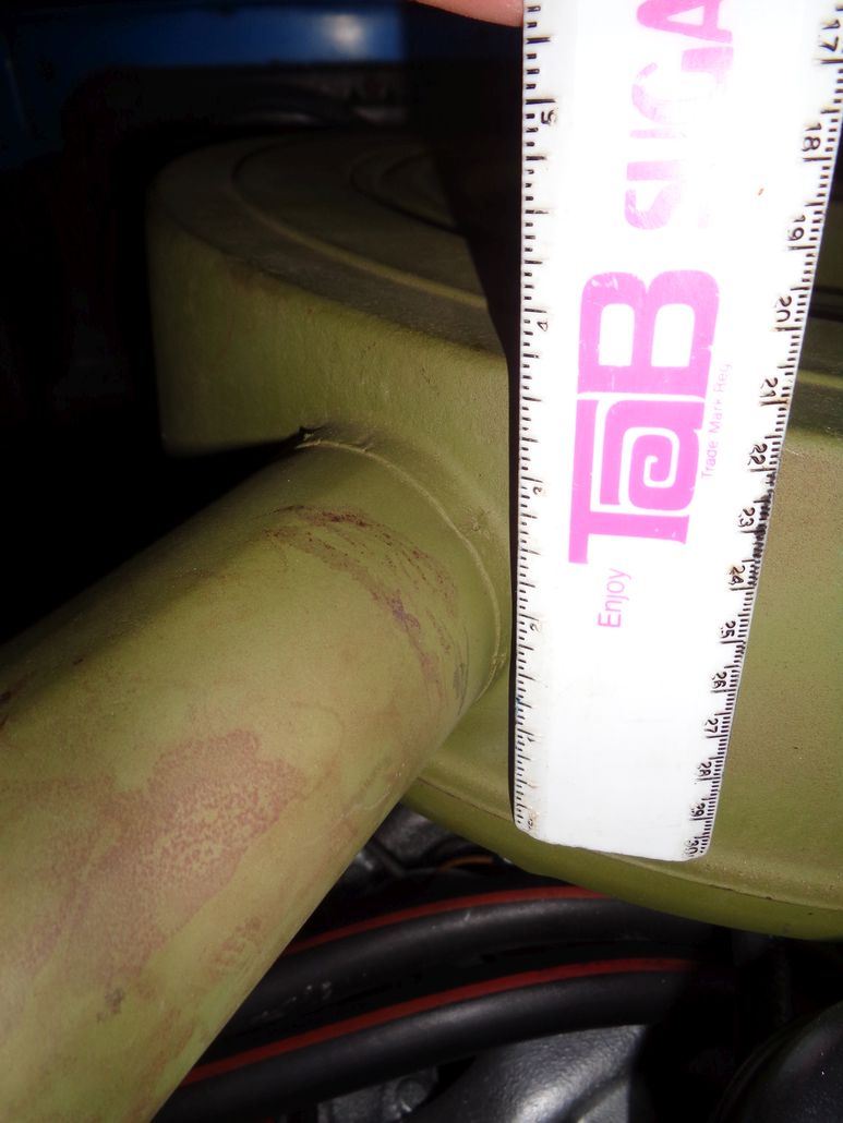
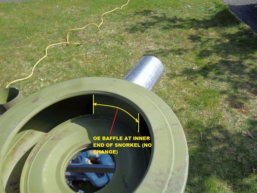
The snorkel isn't 3".  It is just 2.5" so I am likely going to have to make the inlet snorkel bigger. The side of the can is just over 3.5" so 4" is out but something a bit bigger than 3" might work. I suppose ovalish rectangular is possible too with a modification of the internal baffle that chases the incoming air around the inside of the can. It is just 2.5" so I am likely going to have to make the inlet snorkel bigger. The side of the can is just over 3.5" so 4" is out but something a bit bigger than 3" might work. I suppose ovalish rectangular is possible too with a modification of the internal baffle that chases the incoming air around the inside of the can.
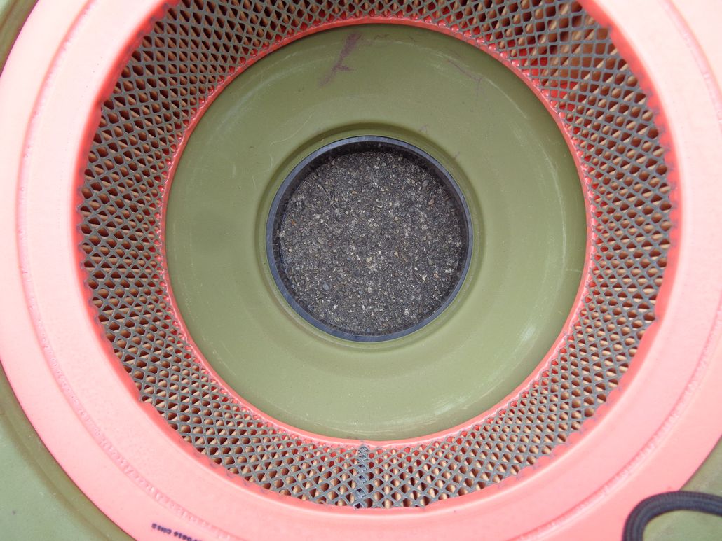
The WIX 42041 that I picked up yesterday fits perfectly. Quality piece. Made in Poland, not China.
Here are some photos from 30 minutes ago:
 (eBayGoldenLionAirCleanerOn56D5004bblHemi.jpg) (eBayGoldenLionAirCleanerOn56D5004bblHemi.jpg)
 (eBayGoldenLionAirCleanerOn56D5004bblHemi_FitmentAtCarbThroat.jpg) (eBayGoldenLionAirCleanerOn56D5004bblHemi_FitmentAtCarbThroat.jpg)
 (eBayGoldenLionAirCleanerOn56D5004bblHemi_WithWIX42041Filter.jpg) (eBayGoldenLionAirCleanerOn56D5004bblHemi_WithWIX42041Filter.jpg)
 (eBayGoldenLionAirCleanerOn56D5004bblHemi_WithWIX42041FilterAndOEPiePlate.jpg) (eBayGoldenLionAirCleanerOn56D5004bblHemi_WithWIX42041FilterAndOEPiePlate.jpg)
 (eBayGoldenLionAirCleanerOn56D5004bblHemi_SnorkelToScoopPathway_Annotated.jpg) (eBayGoldenLionAirCleanerOn56D5004bblHemi_SnorkelToScoopPathway_Annotated.jpg)
 (eBayGoldenLionAirCleanerOn56D5004bblHemi_SnorkelInsideDiameter2point5inches.jpg) (eBayGoldenLionAirCleanerOn56D5004bblHemi_SnorkelInsideDiameter2point5inches.jpg)
 (eBayGoldenLionAirCleanerOn56D5004bblHemi_Snorkel_BaffleAtInnerEnd.jpg) (eBayGoldenLionAirCleanerOn56D5004bblHemi_Snorkel_BaffleAtInnerEnd.jpg)
 (eBayGoldenLionAirCleanerOn56D5004bblHemi_CanSideHeight3point5Inches.jpg) (eBayGoldenLionAirCleanerOn56D5004bblHemi_CanSideHeight3point5Inches.jpg)
 (eBayGoldenLionAirCleanerOn56D5004bblHemi_InterferencesWithChokeAndFuelLine.jpg) (eBayGoldenLionAirCleanerOn56D5004bblHemi_InterferencesWithChokeAndFuelLine.jpg)
 (eBayGoldenLionAirCleanerOn56D5004bblHemi_InterferenceWithPSPump.jpg) (eBayGoldenLionAirCleanerOn56D5004bblHemi_InterferenceWithPSPump.jpg)
 (eBayGoldenLionAirCleanerOn56D5004bblHemi_InterferenceWithPSPump_1.jpg) (eBayGoldenLionAirCleanerOn56D5004bblHemi_InterferenceWithPSPump_1.jpg)
Attachments
----------------
eBayGoldenLionAirCleanerOn56D5004bblHemi.jpg (162KB - 559 downloads)
eBayGoldenLionAirCleanerOn56D5004bblHemi_FitmentAtCarbThroat.jpg (82KB - 602 downloads)
eBayGoldenLionAirCleanerOn56D5004bblHemi_WithWIX42041Filter.jpg (120KB - 573 downloads)
eBayGoldenLionAirCleanerOn56D5004bblHemi_WithWIX42041FilterAndOEPiePlate.jpg (124KB - 565 downloads)
eBayGoldenLionAirCleanerOn56D5004bblHemi_SnorkelToScoopPathway_Annotated.jpg (220KB - 565 downloads)
eBayGoldenLionAirCleanerOn56D5004bblHemi_SnorkelInsideDiameter2point5inches.jpg (71KB - 556 downloads)
eBayGoldenLionAirCleanerOn56D5004bblHemi_Snorkel_BaffleAtInnerEnd.jpg (73KB - 557 downloads)
eBayGoldenLionAirCleanerOn56D5004bblHemi_CanSideHeight3point5Inches.jpg (91KB - 568 downloads)
eBayGoldenLionAirCleanerOn56D5004bblHemi_InterferencesWithChokeAndFuelLine.jpg (115KB - 562 downloads)
eBayGoldenLionAirCleanerOn56D5004bblHemi_InterferenceWithPSPump.jpg (115KB - 562 downloads)
eBayGoldenLionAirCleanerOn56D5004bblHemi_InterferenceWithPSPump_1.jpg (115KB - 567 downloads)
|
|
| |
|
Expert 5K+
Posts: 9900
Location: Lower Mainland BC | 
Well Dave, I see you have a clearance problem, Dave

Why yes HAL, I do have a clearance problem, HAL.
Well Dave, have you considered making a spacer instead of using a ball peen hammer, to solve your problem, Dave?
Well, no HAL, I had not. What do you suggest HAL?
Well Dave, have you had a look at the McNichols pipe sizing chart, Dave?
Well, not HAL, I have not. Do you mean this one, HAL? http://www.mcnichols.com/?pageCode=pipedims
Yes Dave, that is the one. Perhaps you could consider a Schedule 10 Nominal 4 inch pipe. It has a 4.5" outside diameter and a 4.26" inside diameter. I believe you will find that the 4.26" ID will sit on the carburetor nicely Dave and the air cleaner will sit on the 4.5" OD nicely as well, Dave.
Well, HAL thank you very much for that. Now, could you please open the Pod bay door. I really, *really*, need to pee.
I'm sorry Dave, I'm afraid I can't do that. This conversation can serve no purpose anymore. Good bye Dave.
Edited by 56D500boy 2018-03-25 12:29 AM
|
|
| |
|
Expert 5K+
Posts: 9664
Location: So. Cal | Why not use the standard choke well instead of that electric choke? I have the standard one hooked up to my '58 Coronet and it works great. Electric chokes are never as good. |
|
| |
|
Expert 5K+
Posts: 9900
Location: Lower Mainland BC | Powerflite - 2018-03-24 6:13 PM
Why not use the standard choke well instead of that electric choke? I have the standard one hooked up to my '58 Coronet and it works great. Electric chokes are never as good.
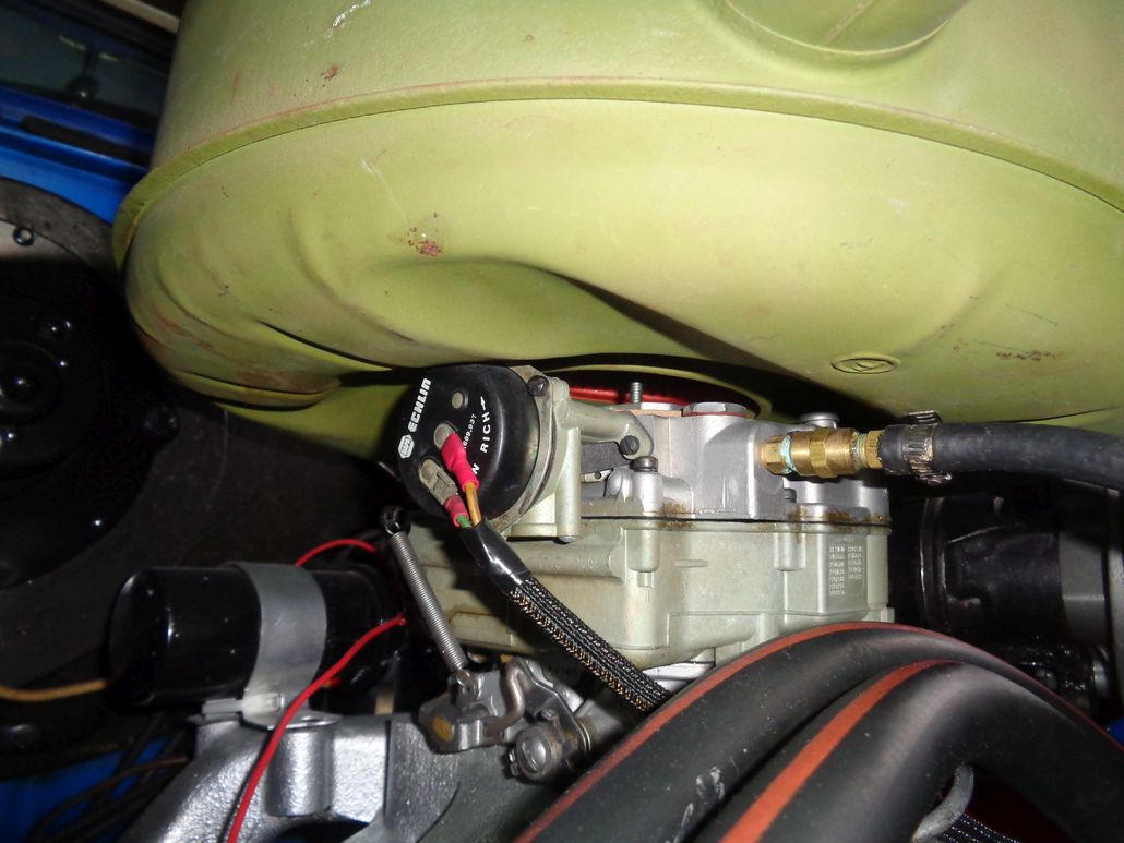
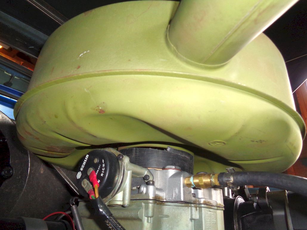
My 56 Dodge came with that Echlin Electric choke and no signs of any exhaust-heated mechanical choke mechanism *OR* the tubing/whatever to connect the exhaust manifold to the carb.
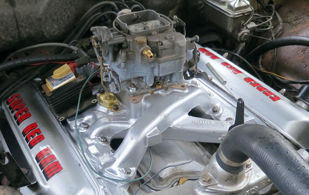
I don't have this stuff (as shown on this beautiful very correct local 55 Custom Royal early 270 hemi with Powerpack 4 bbl below). I don't think a mechanical choke would solve my current clearance problem.
Edited by 56D500boy 2018-03-24 7:32 PM
|
|
| |
|
Expert 5K+
Posts: 9664
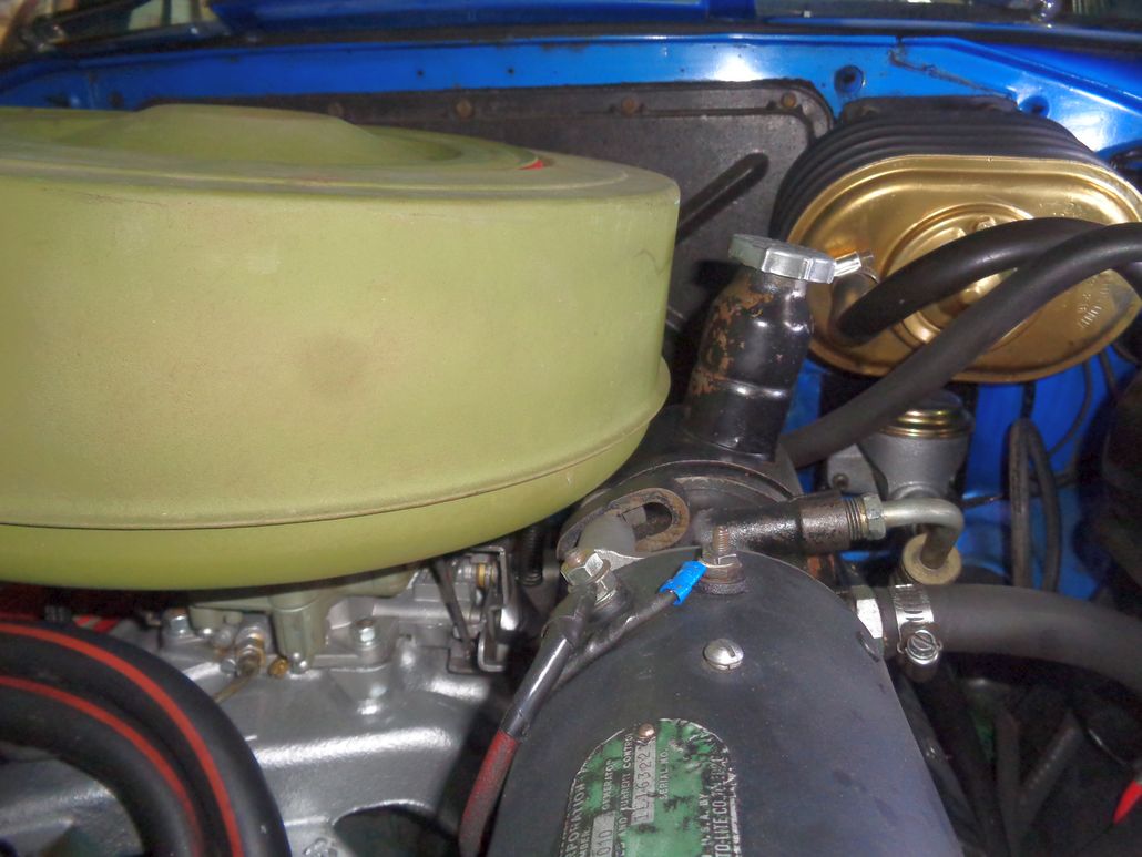
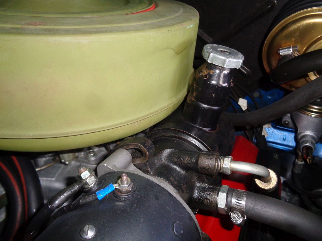
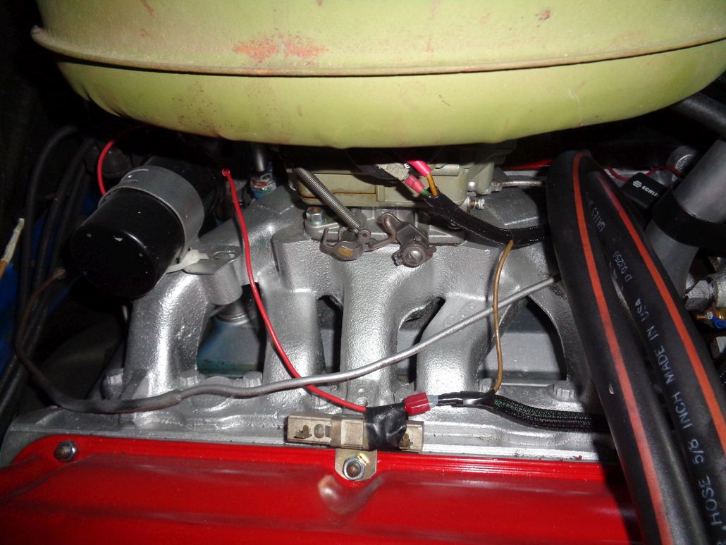
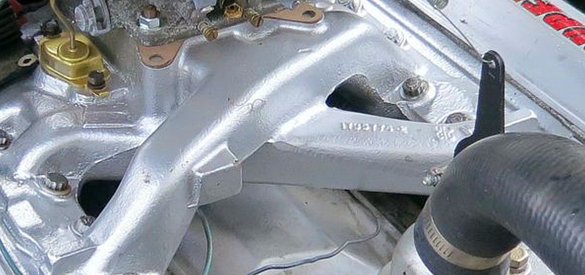
Location: So. Cal | The 315 4bbl manifold should have the provision for it at least, like mine does.
 (325Poly.jpg) (325Poly.jpg)
Attachments
----------------
325Poly.jpg (144KB - 550 downloads)
|
|
| |
|
Expert 5K+
Posts: 9900
Location: Lower Mainland BC | Powerflite - 2018-03-24 8:10 PM
The 315 4bbl manifold should have the provision for it at least, like mine does.
Made me look. But nope.
 (315HemiIntakeShowingNoChokeHeatPad.jpg) (315HemiIntakeShowingNoChokeHeatPad.jpg)
 (315HemiRightExhaustManifoldWithPotentialChokeHeatNipple.jpg) (315HemiRightExhaustManifoldWithPotentialChokeHeatNipple.jpg)
Attachments
----------------
315HemiIntakeShowingNoChokeHeatPad.jpg (136KB - 558 downloads)
315HemiRightExhaustManifoldWithPotentialChokeHeatNipple.jpg (108KB - 545 downloads)
|
|
| |
|
Expert 5K+
Posts: 9664
Location: So. Cal | Wow, I learn something new everyday. I had no idea there were different versions of a 315-325 4bbl intake. |
|
| |
|
Expert 5K+
Posts: 9900
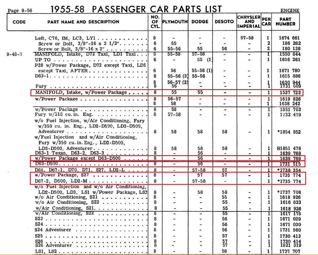
Location: Lower Mainland BC | It would appear that the 1955 Dodge 4bbl intake, the 1956 non-D500 power package, the 1956 D500 4 bbl intake and the 1957-58 4 bbl intakes all have different PNs. Interestingly, the one in your photo Nathan with the casting number of 1735 774 is indeed the Part Number for the 1957-58 4 bbl power package and D500 intake manifold. Very odd.
Edited by 56D500boy 2018-03-25 12:43 AM
 (IntakeManifoldPNs.jpg) (IntakeManifoldPNs.jpg)
Attachments
----------------
IntakeManifoldPNs.jpg (190KB - 554 downloads)
|
|
| |
|
Expert 5K+
Posts: 9664
Location: So. Cal | The 270 intake is obviously a different part because it isn't interchangeable with the 315-325. I am surprised you could read my casting number, but you are right. |
|
| |
|
Expert 5K+
Posts: 9900
Location: Lower Mainland BC | Powerflite - 2018-03-25 10:56 AM
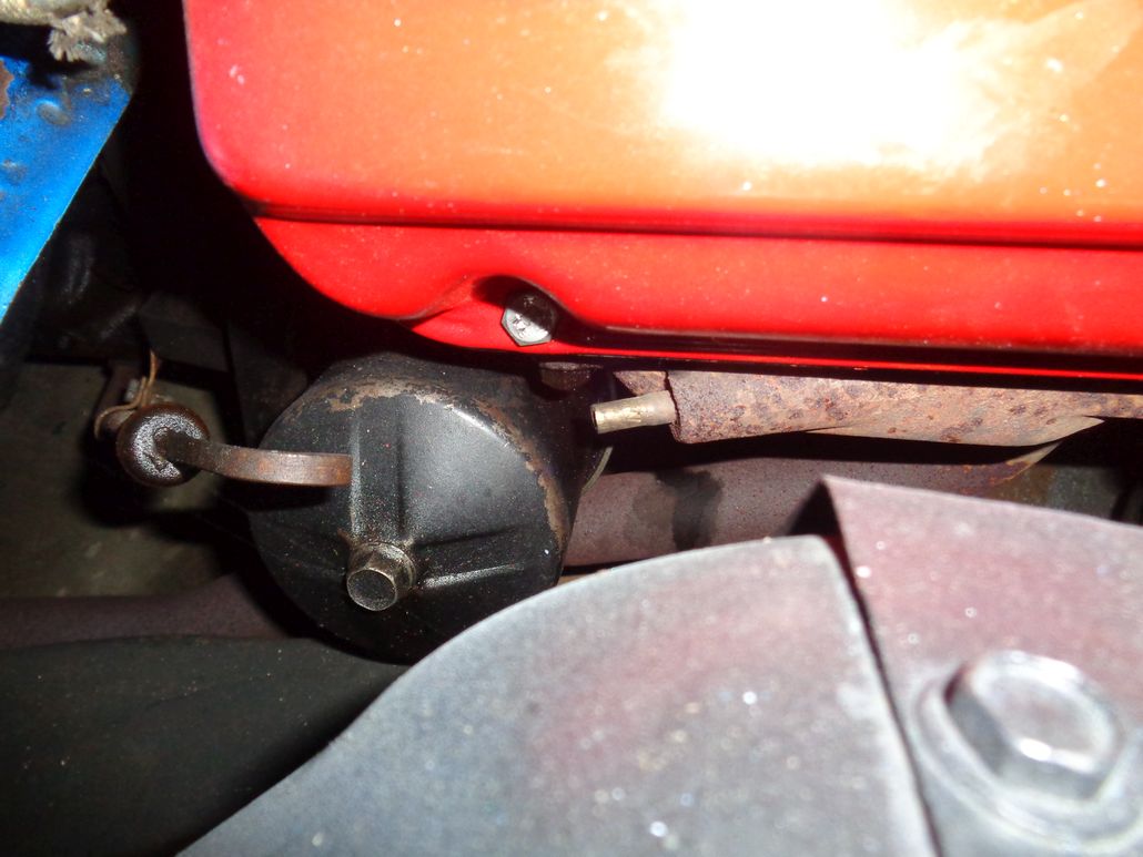
The 270 intake is obviously a different part because it isn't interchangeable with the 315-325. I am surprised you could read my casting number, but you are right. :)
I could read your 58 intake casting number even before I blew the photo up like below. Luck not, skill.
I have some 4" nominal ABS black plumbing pipe in the shed that I am going to pull out and see if an inch of it will work as an aircleaner spacer. Then I need to find my electric Styrofoam shaper and start on shaping the inlet air scoop (after I remove the right horn).
 (58Dodge4bblIntake1735774.jpg) (58Dodge4bblIntake1735774.jpg)
Attachments
----------------
58Dodge4bblIntake1735774.jpg (101KB - 539 downloads)
|
|
| |
|
Expert 5K+
Posts: 9900
Location: Lower Mainland BC | 56D500boy - 2018-03-25 12:02 PM
I have some 4" nominal ABS black plumbing pipe in the shed that I am going to pull out and see if an inch of it will work as an aircleaner spacer. Then I need to find my electric Styrofoam shaper and start on shaping the inlet air scoop (after I remove the right horn).
Had a few minutes before we went out for Sunday brunch so I found the ABS pipe bit that I have been saving for a rainy day. Didn't measure anything, just cut (very crudely ) what I thought would be needed and trialed it. It was Schedule 40 so the wall thickness is a bit much and would need some trimming at the carb. Might need something else at the top, where the air cleaner sits on it. Nevertheless, it does show that a spacer is probably doable and the way to go.
I do have 4 more feet of pipe to cut a nice 1.25" ring if I decide to stick with Schedule 40 (and not Schedule 10 as I thought would work better).
The proof of concept photos:
Edited by 56D500boy 2018-03-25 5:03 PM
 (CrudelyCutSchedule40ABSSpacer_1.jpg) (CrudelyCutSchedule40ABSSpacer_1.jpg)
 (CrudelyCutSchedule40ABSSpacer_2.jpg) (CrudelyCutSchedule40ABSSpacer_2.jpg)
 (eBayGoldenLionAirCleanerSittingOnTrialSchedule40ABSSpacer.jpg) (eBayGoldenLionAirCleanerSittingOnTrialSchedule40ABSSpacer.jpg)
 (CrudelyCutSchedule40ABSSpacerWithEbayGoldenLionAirCleanerShowingClearanceGained.jpg) (CrudelyCutSchedule40ABSSpacerWithEbayGoldenLionAirCleanerShowingClearanceGained.jpg)
Attachments
----------------
CrudelyCutSchedule40ABSSpacer_1.jpg (122KB - 553 downloads)
CrudelyCutSchedule40ABSSpacer_2.jpg (148KB - 540 downloads)
eBayGoldenLionAirCleanerSittingOnTrialSchedule40ABSSpacer.jpg (158KB - 527 downloads)
CrudelyCutSchedule40ABSSpacerWithEbayGoldenLionAirCleanerShowingClearanceGained.jpg (108KB - 535 downloads)
|
|
| |
|
Expert 5K+
Posts: 7400
Location: northern germany | if you are good with metal and a welder that elevated position of the ac hsg will make it easy to fabricate a smooth transition from ac hsg floor to carburetor throat. |
|
| |
|
Expert
Posts: 3575
Location: Netherlands | With the risc of showing my cheapness here I can say; don't overlook the kitchen utilities like a simple small cooking pan to modify it as a carb/af-housing spacer...
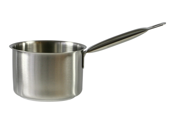
(Been there done that...) |
|
| |
|
Expert 5K+
Posts: 7400
Location: northern germany | BigBlockMopar - 2018-03-25 6:26 PM
With the risc of showing my cheapness here I can say; don't overlook the kitchen utilities like a simple small cooking pan to modify it as a carb/af-housing spacer...
(Been there done that...) :)
haha, i have a couple of household items in my car, like a christmas tree ornament peak in my air cleaner cover and an old bucket as an alternator fan shroud and i was even cheaper as i used an old platic bucket as an ac hsg spacer
Edited by 1960fury 2018-03-25 7:23 PM
|
|
| |
|
Expert 5K+
Posts: 9900
Location: Lower Mainland BC | 1960fury - 2018-03-25 5:38 PM
if you are good with metal and a welder that elevated position of the ac hsg will make it easy to fabricate a smooth transition from ac hsg floor to carburetor throat.
BigBlockMopar - 2018-03-25 6:26 PM
With the risk of showing my cheapness here I can say; don't overlook the kitchen utilities like a simple small cooking pan to modify it as a carb/af-housing spacer...
(Been there done that...) :)
Thanks for the comments. I like the way you guys think.
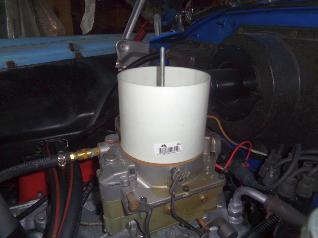
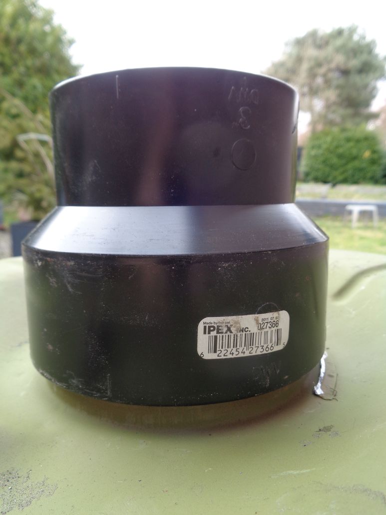
I don't have any welding or CNC skills (wish I did). What I do have is the type of mind that can see re-purposing something, like a cooking pan, if the size was right. I didn't see either of your two posts guys before I went out to the local Medium-Box Hardware store, "RONA", was the Canadian version of Lowes/Home Depot (now owned by Lowes but still called RONA). I actually went to buy some styrofoam bead board to laminate and to start sculpting the shape of the air scoop. However, I also wandered into the plumbing section where I bought a 4" x 3" (both nominal) ABS black plastic reducing coupling and a 4" x 4" thin-wall PVC coupling. The 4" end of the reducing coupling fits over the 4" nominal Schedule 40 black plastic plumbing pipe *AND* the 4" nominal PVC coupling. The ABS reducer was $7.89 and the PVC coupling was $2.49. The "Transition" glue to bond the ABS and PVC was $4.99. So not much money into it.
Got those all home and started to work.
First thing was to test the 4" x 4" PVC coupling on the carb. Must be Schedule 10 because it fit perfectly over the carb. Nothing to trim out there (except height).
Then I tried the 4" x 3" reducer on the bottom flange/nipple of the Golden Lion aircleaner at the 4" nominal end. A bit tight. Needs some grinding/sanding to fit better. No biggy.
Then I cut the 4" x 3" reducer at the 4" nominal end to create a collar to corral the 4" nominal PVC coupling. Cut it about 3/4" high on my table saw (cutting ABS stinks BTW).
Sanded off the burrs from sawing and pushed the new collar on to the bottom of the air cleaner. Then I inserted the white PVC coupling into the collar. Fit beautifully.
Then, without cutting the white PVC coupling but leaving it in the ABS collar that was pushed onto the air cleaner, I tried the assembly on the carburetor. Definitely got clearance now (LOL). Tomorrow, I will figure out what the real height I need is and then cut the coupling. I have two halves to get it right. Even if I screw both of them up, the coupling was only $2.49 and I can get another one and try again.
I might incorporate the remaining bit of the 4" x 3" reducing coupling into the air scoop because the OD of the 3" nominal end is pretty much 4" and 4" flex hose would fit over it. Just need to make the snorkel on the air cleaner appropriately larger.
Edited by 56D500boy 2018-03-25 9:00 PM
 (FourInchNominalPVCCouplingUnCutOn56D500WCFBCarburetor_1.jpg) (FourInchNominalPVCCouplingUnCutOn56D500WCFBCarburetor_1.jpg)
 (FourInchNominalPVCCouplingUnCutOn56D500WCFBCarburetor_2.jpg) (FourInchNominalPVCCouplingUnCutOn56D500WCFBCarburetor_2.jpg)
 (4InchX3InchABSReducingCouplingSittingOnUndersideOfGoldenLionAirCleaner.jpg) (4InchX3InchABSReducingCouplingSittingOnUndersideOfGoldenLionAirCleaner.jpg)
 (SectionOf4inchX3inchABSReducingCouplingPushedDownOverBottomOfGoldenLionAircleaner.jpg) (SectionOf4inchX3inchABSReducingCouplingPushedDownOverBottomOfGoldenLionAircleaner.jpg)
 (FourInchNominalPVCCouplingInsertedIntoSectionOf4inchX3inchABSReducingCouplingOnGoldenLionAirCleaner_1.jpg) (FourInchNominalPVCCouplingInsertedIntoSectionOf4inchX3inchABSReducingCouplingOnGoldenLionAirCleaner_1.jpg)
 (FourInchNominalPVCCouplingInsertedIntoSectionOf4inchX3inchABSReducingCouplingOnGoldenLionAirCleaner_2.jpg) (FourInchNominalPVCCouplingInsertedIntoSectionOf4inchX3inchABSReducingCouplingOnGoldenLionAirCleaner_2.jpg)
 (FourInchNominalPVCCouplingUnCutOn56D500WCFBCarburetor_3.jpg) (FourInchNominalPVCCouplingUnCutOn56D500WCFBCarburetor_3.jpg)
 (FourInchNominalPVCCouplingUnCutOn56D500WCFBCarburetor_4.jpg) (FourInchNominalPVCCouplingUnCutOn56D500WCFBCarburetor_4.jpg)
Attachments
----------------
FourInchNominalPVCCouplingUnCutOn56D500WCFBCarburetor_1.jpg (101KB - 537 downloads)
FourInchNominalPVCCouplingUnCutOn56D500WCFBCarburetor_2.jpg (109KB - 528 downloads)
4InchX3InchABSReducingCouplingSittingOnUndersideOfGoldenLionAirCleaner.jpg (84KB - 519 downloads)
SectionOf4inchX3inchABSReducingCouplingPushedDownOverBottomOfGoldenLionAircleaner.jpg (99KB - 541 downloads)
FourInchNominalPVCCouplingInsertedIntoSectionOf4inchX3inchABSReducingCouplingOnGoldenLionAirCleaner_1.jpg (83KB - 524 downloads)
FourInchNominalPVCCouplingInsertedIntoSectionOf4inchX3inchABSReducingCouplingOnGoldenLionAirCleaner_2.jpg (80KB - 509 downloads)
FourInchNominalPVCCouplingUnCutOn56D500WCFBCarburetor_3.jpg (76KB - 521 downloads)
FourInchNominalPVCCouplingUnCutOn56D500WCFBCarburetor_4.jpg (127KB - 536 downloads)
|
|
| |
|
Expert 5K+
Posts: 7400
Location: northern germany | 1960fury - 2018-03-25 5:38 PM
if you are good with metal and a welder that elevated position of the ac hsg will make it easy to fabricate a smooth transition from ac hsg floor to carburetor throat.
this is what i meant. old salt flat trick. i read many years ago that this will improve noticable HP and topspeed and of course i went all out with that, like i always do
some mods inside the carb throat too.
Edited by 1960fury 2018-03-26 5:26 PM
 (ramfuryds2.jpg) (ramfuryds2.jpg)
 (ov_achsgfloor1 (1).jpg) (ov_achsgfloor1 (1).jpg)
 (ov_actop1 (1).jpg) (ov_actop1 (1).jpg)
Attachments
----------------
ramfuryds2.jpg (55KB - 520 downloads)
ov_achsgfloor1 (1).jpg (69KB - 517 downloads)
ov_actop1 (1).jpg (71KB - 522 downloads)
|
|
| |
|
Expert 5K+
Posts: 7400
Location: northern germany | 1960fury - 2018-03-25 7:20 PM
BigBlockMopar - 2018-03-25 6:26 PM
With the risc of showing my cheapness here I can say; don't overlook the kitchen utilities like a simple small cooking pan to modify it as a carb/af-housing spacer...
(Been there done that...) :)
haha, i have a couple of household items in my car, like a christmas tree ornament peak in my air cleaner cover....
of course not for ornamentation, i hate ornamentation and bling-bling in the engine compartment, i just glued the christmas tip to the AC top as it had the perfect shape to improve airflow:
 (ov_actop (1).jpg) (ov_actop (1).jpg)
Attachments
----------------
ov_actop (1).jpg (58KB - 516 downloads)
|
|
| |
|
Expert 5K+
Posts: 9900
Location: Lower Mainland BC | Good work there Sid. Looks like the airflow would be very smooth.
What about covering those little air tubes on the outside of the main carb body?
Yours:

What are the black flexi-ducts?

These little tubes:
 (SmallAirTubesOnEdgeOf56WCFB.jpg) (SmallAirTubesOnEdgeOf56WCFB.jpg)
Attachments
----------------
SmallAirTubesOnEdgeOf56WCFB.jpg (148KB - 515 downloads)
|
|
| |
|
Expert 5K+
Posts: 9900
Location: Lower Mainland BC | AIR SCOOP SIZING TRIALS
Yesterday I bought a piece of 3" Styrofoam bead board to use to trial an air scoop. I cut it in quarters and laminated two of the pieces together and left the other two pieces loose.
I couldn't find my electric Styrofoam shaper "knife" but I did find my dry wall saw. The saw results in white bead board snow so I better find the electric shaper before I finalize the scoop and start with the fibreglassing, etc.
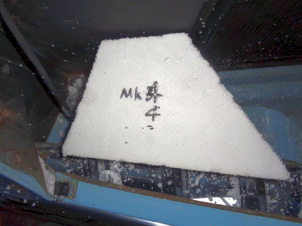
In the following sequence, Mark 1 and 2 are single thickness and Marks 3 and 4 are double thickness.
I removed the right side horn for now but I had problems with wiring to the right signal/park light. They ran the wires very awkwardly and they are in the way of the ultimate scoop. I would like to run the wiring better but I think it is a major job to remove the signal light, etc. So for now I left it.
As a result of the wiring, the some of the differences between Mk. 1 and 2 and Mk. 3 and 4 are trimming the scoop to avoid the wiring.
Mark 1 was a single layer trial with notches to clear the teeth on the grill bar. Mark 2 was based on Mark 1 but was trimmed shorter to avoid the bar grill teeth area.
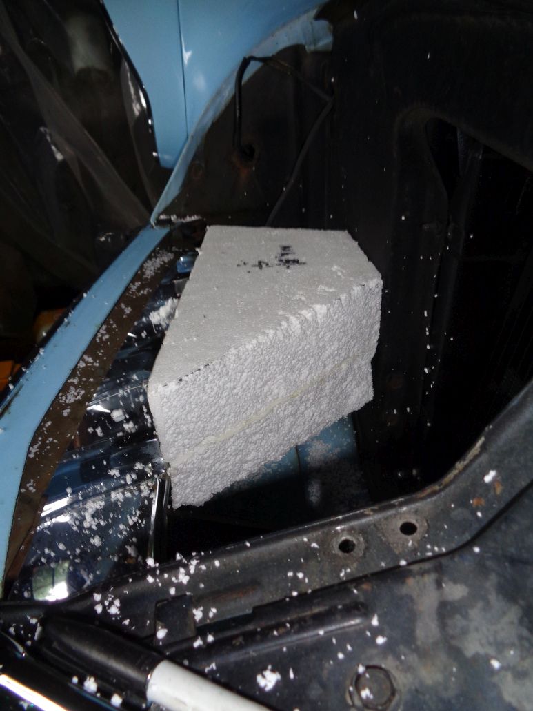
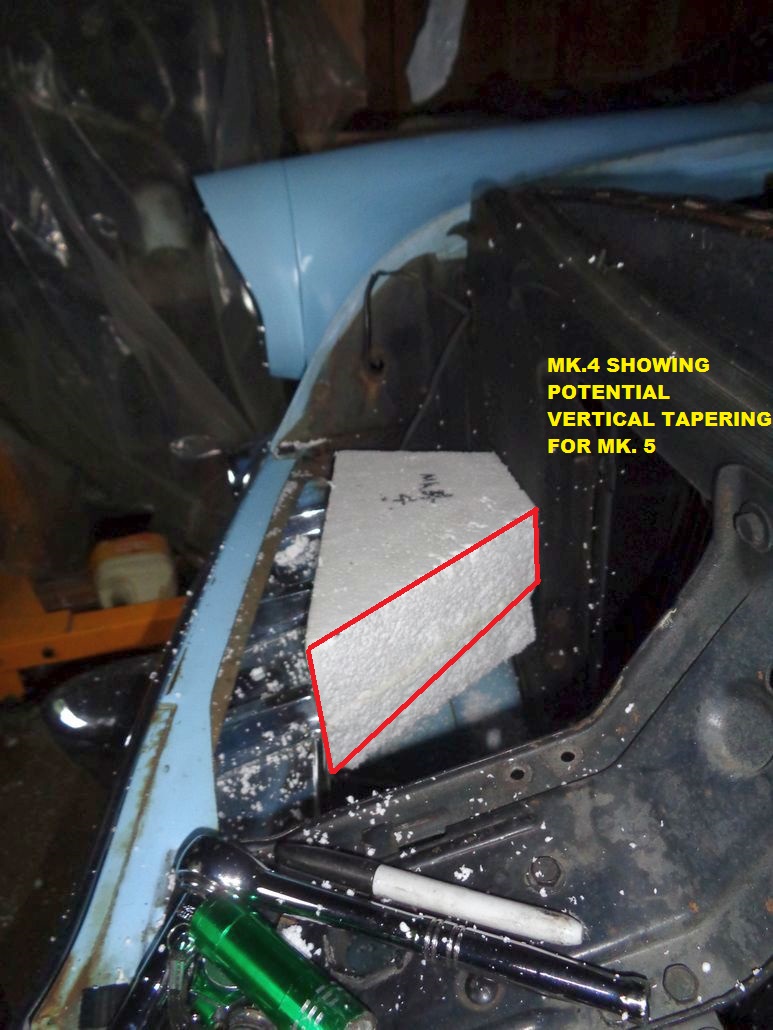
Mark 3 was a double layer scoop based on the Mark 1 plan view but twice the thickness. This gets a bit more air but would require tapering in the vertical at the rear to work better.
Mark 4 was Mark 3 with some additional trimming to avoid the signal/park light wiring.
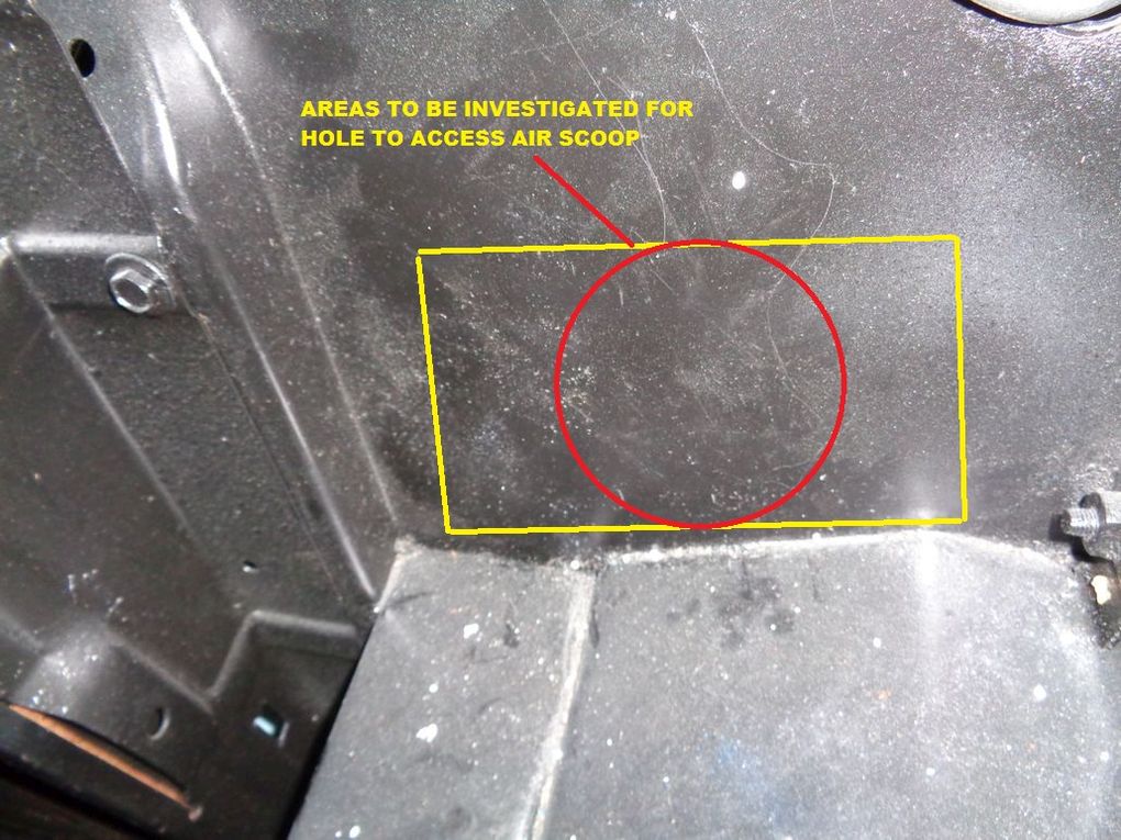
The hole in the rad support could be either round or rectangular. I think rectangular and then a transition to round. But who knows.
Need to buy more foam and find my electric foam sculpting hot knife for Mk. 5 trials.
Edited by 56D500boy 2018-03-27 1:06 AM
 (56DodgeAirScoopTrials_Mk1_Top.jpg) (56DodgeAirScoopTrials_Mk1_Top.jpg)
 (56DodgeAirScoopTrials_Mk1_side.jpg) (56DodgeAirScoopTrials_Mk1_side.jpg)
 (56DodgeAirScoopTrials_Mk1_Front.jpg) (56DodgeAirScoopTrials_Mk1_Front.jpg)
 (56DodgeAirScoopTrials_Mk2_Top.jpg) (56DodgeAirScoopTrials_Mk2_Top.jpg)
 (56DodgeAirScoopTrials_Mk3_Top.jpg) (56DodgeAirScoopTrials_Mk3_Top.jpg)
 (56DodgeAirScoopTrials_Mk3_Front_1.jpg) (56DodgeAirScoopTrials_Mk3_Front_1.jpg)
 (56DodgeAirScoopTrials_Mk3_Front_2.jpg) (56DodgeAirScoopTrials_Mk3_Front_2.jpg)
 (56DodgeAirScoopTrials_Mk4_Top.jpg) (56DodgeAirScoopTrials_Mk4_Top.jpg)
 (56DodgeAirScoopTrials_Mk4_SideView.jpg) (56DodgeAirScoopTrials_Mk4_SideView.jpg)
 (56DodgeAirScoopTrials_Mk4_SideView_ShowingPotentialTapering.jpg) (56DodgeAirScoopTrials_Mk4_SideView_ShowingPotentialTapering.jpg)
 (56DodgeAirScoopTrials_AreaInRadsupportForConnectionHoleToScoop.jpg) (56DodgeAirScoopTrials_AreaInRadsupportForConnectionHoleToScoop.jpg)
 (56DodgeAirScoopTrials_Mk4_TopWithPathToAirCleaner.jpg) (56DodgeAirScoopTrials_Mk4_TopWithPathToAirCleaner.jpg)
 (56DodgeAirScoopTrials_PotentialMark5TopShape.jpg) (56DodgeAirScoopTrials_PotentialMark5TopShape.jpg)
 (56DodgeAirScoopTrials_PotentialMark5SideShape.jpg) (56DodgeAirScoopTrials_PotentialMark5SideShape.jpg)
Attachments
----------------
56DodgeAirScoopTrials_Mk1_Top.jpg (90KB - 522 downloads)
56DodgeAirScoopTrials_Mk1_side.jpg (111KB - 513 downloads)
56DodgeAirScoopTrials_Mk1_Front.jpg (141KB - 520 downloads)
56DodgeAirScoopTrials_Mk2_Top.jpg (104KB - 519 downloads)
56DodgeAirScoopTrials_Mk3_Top.jpg (100KB - 504 downloads)
56DodgeAirScoopTrials_Mk3_Front_1.jpg (136KB - 521 downloads)
56DodgeAirScoopTrials_Mk3_Front_2.jpg (122KB - 513 downloads)
56DodgeAirScoopTrials_Mk4_Top.jpg (123KB - 507 downloads)
56DodgeAirScoopTrials_Mk4_SideView.jpg (128KB - 530 downloads)
56DodgeAirScoopTrials_Mk4_SideView_ShowingPotentialTapering.jpg (189KB - 526 downloads)
56DodgeAirScoopTrials_AreaInRadsupportForConnectionHoleToScoop.jpg (164KB - 521 downloads)
56DodgeAirScoopTrials_Mk4_TopWithPathToAirCleaner.jpg (222KB - 513 downloads)
56DodgeAirScoopTrials_PotentialMark5TopShape.jpg (222KB - 524 downloads)
56DodgeAirScoopTrials_PotentialMark5SideShape.jpg (201KB - 523 downloads)
|
|
| |
|
Expert 5K+
Posts: 9900
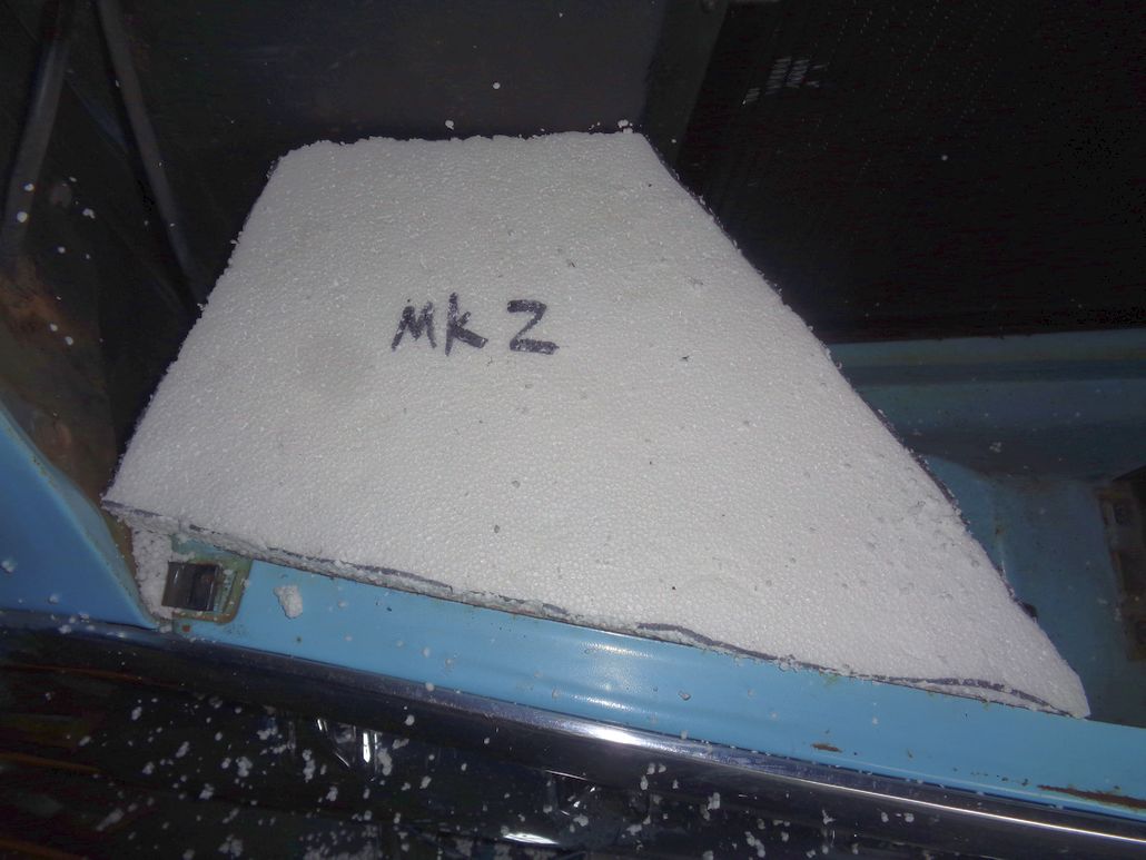
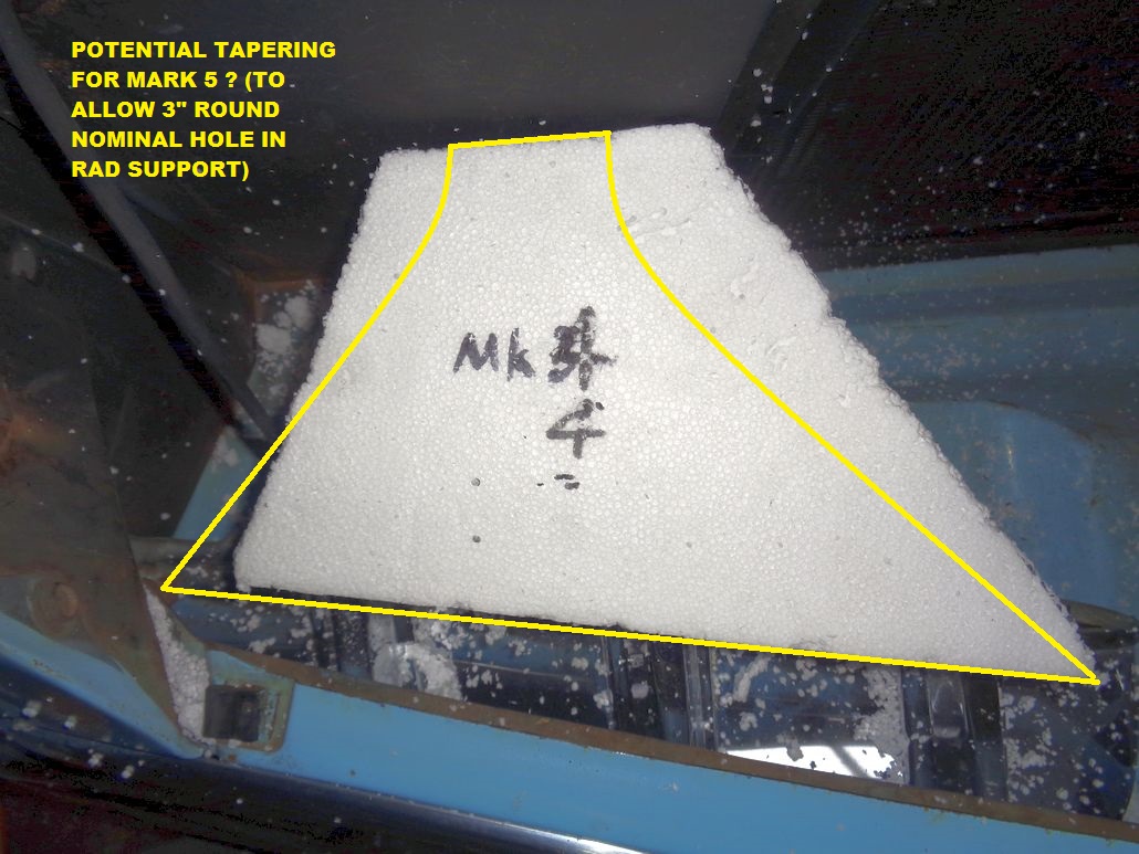
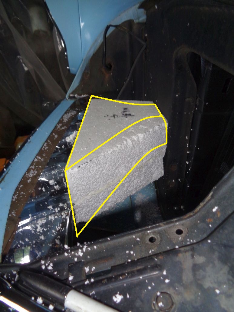
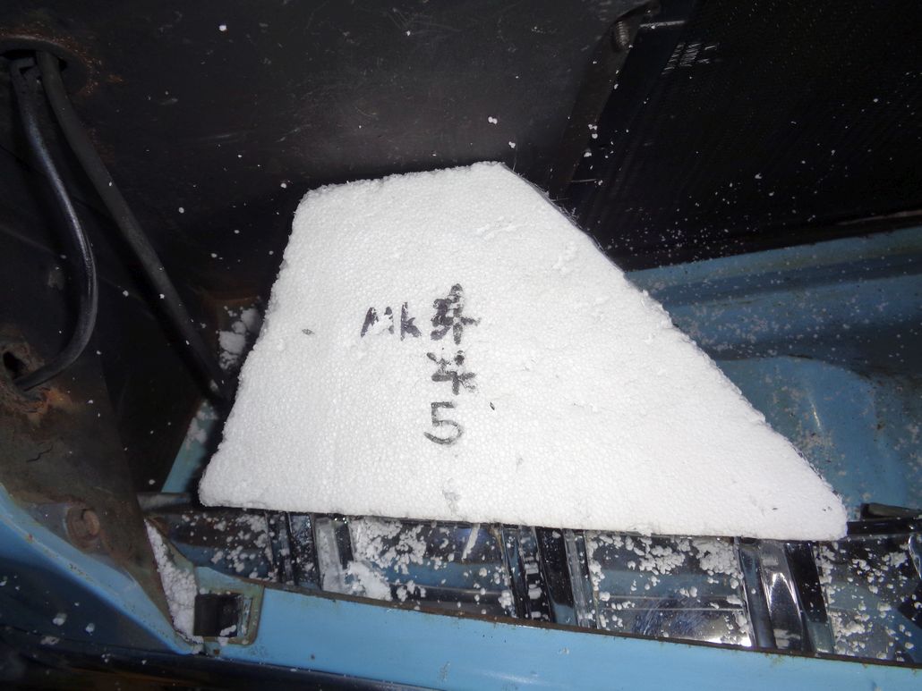
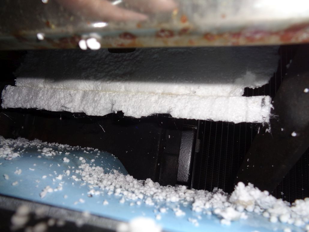
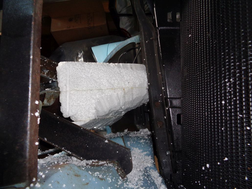
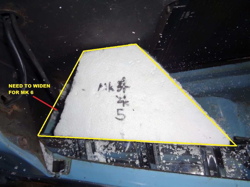
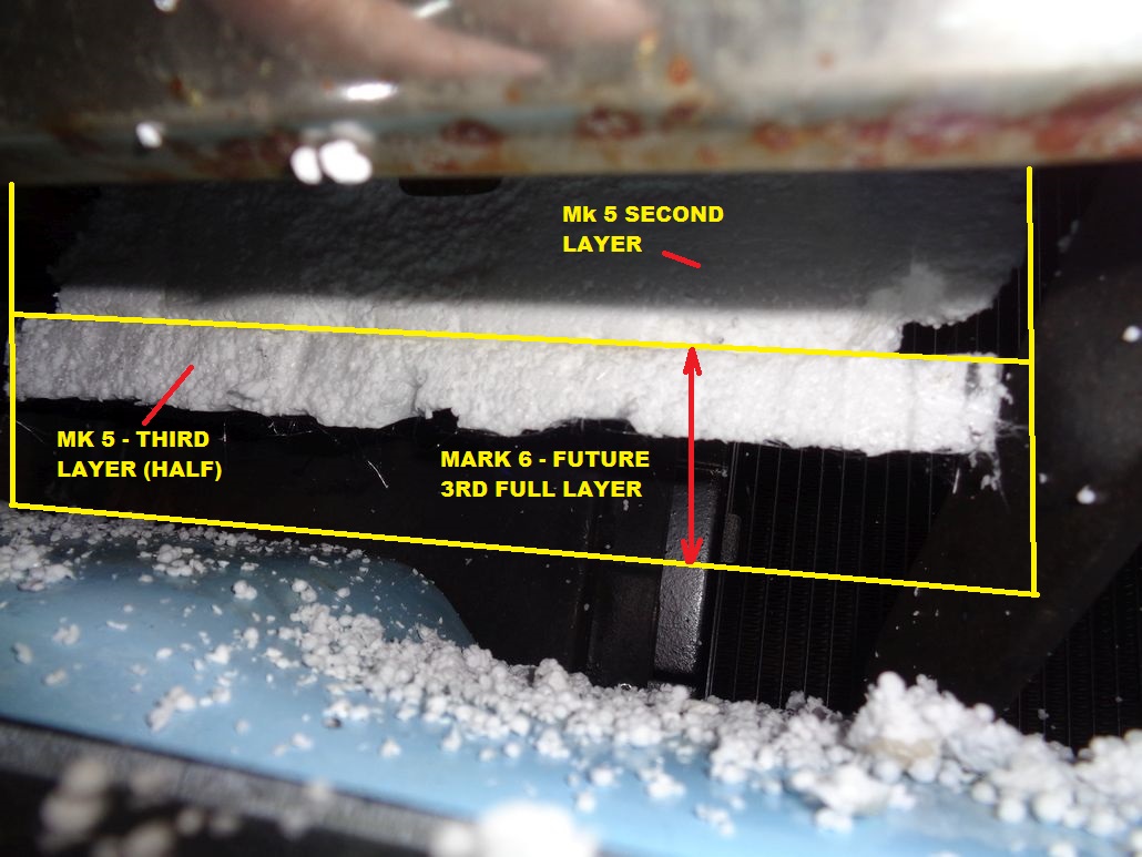
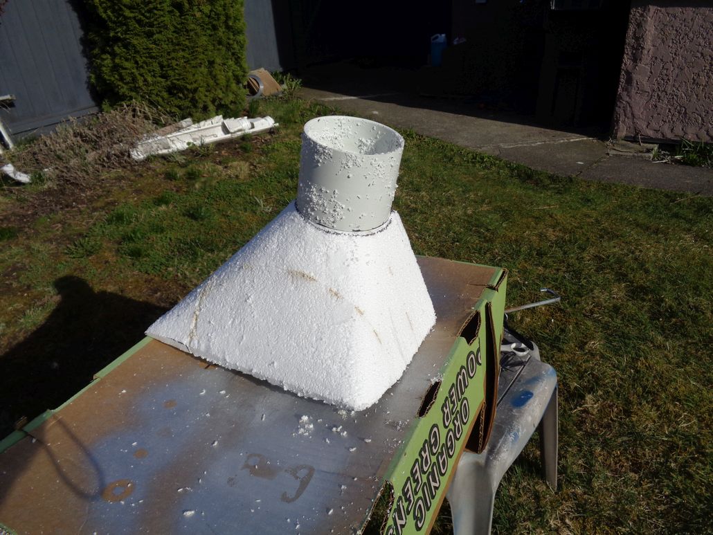
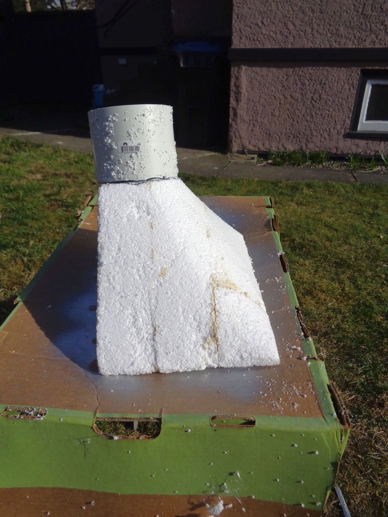
Location: Lower Mainland BC | Mk 5 Air Scoop Trial
I couldn't find my electric foam-cutting wand so I bought another one. (I'll probably find the old one tomorrow LOL).
I didn't buy any new foam so I shaped up the Mark 4 version as the Mark 5. Turns out what I had at the bulkhead/rad support was pretty much the diameter of a Schedule 10 4" PVC coupler which as the same OD as the ID of the 4" nominal aluminum flexi pipe so I didn't cut the scoop down to 3" nominal, just left it at 4" nominal.
I did add part of a third layer at the front bottom before I tapered the scoop on the bottom side. Turns out that I should have added a full third layer before I did the vertical trimming.
Working with the hot foam cutter is tricky. At this point, it is pure concept, not final mould/core so I'm not worried.
The photos below show the Mark 5 results and then the ideas that I need to take forward with the Mark 6 version. I need to buy another piece of foam and laminate three layers and then start again.
 (Mark5FromTheTop.jpg) (Mark5FromTheTop.jpg)
 (Mark5FrontViewWithHalfLayer.jpg) (Mark5FrontViewWithHalfLayer.jpg)
 (Mark5FromTheSide.jpg) (Mark5FromTheSide.jpg)
 (Mark5FromTheTop_Annotated.jpg) (Mark5FromTheTop_Annotated.jpg)
 (Mark5FrontViewWithHalfLayer_Annotated.jpg) (Mark5FrontViewWithHalfLayer_Annotated.jpg)
 (Mark5FromTheSide_Annotated.jpg) (Mark5FromTheSide_Annotated.jpg)
 (Mark5FromTheSide_AnnotatedWithBetterBottomCurve.jpg) (Mark5FromTheSide_AnnotatedWithBetterBottomCurve.jpg)
Attachments
----------------
Mark5FromTheTop.jpg (120KB - 536 downloads)
Mark5FrontViewWithHalfLayer.jpg (99KB - 519 downloads)
Mark5FromTheSide.jpg (152KB - 529 downloads)
Mark5FromTheTop_Annotated.jpg (203KB - 524 downloads)
Mark5FrontViewWithHalfLayer_Annotated.jpg (183KB - 515 downloads)
Mark5FromTheSide_Annotated.jpg (156KB - 515 downloads)
Mark5FromTheSide_AnnotatedWithBetterBottomCurve.jpg (163KB - 506 downloads)
|
|
| |
|
Expert 5K+
Posts: 9900
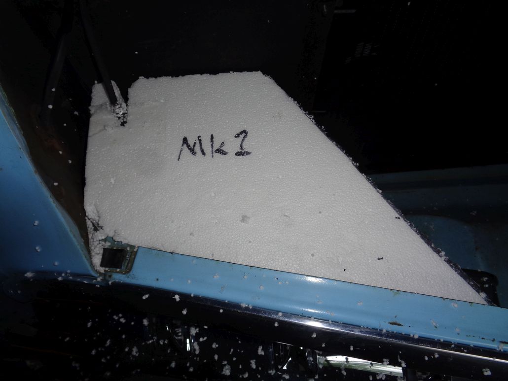
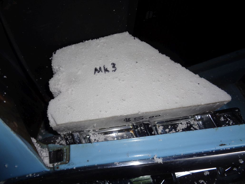
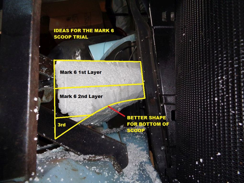
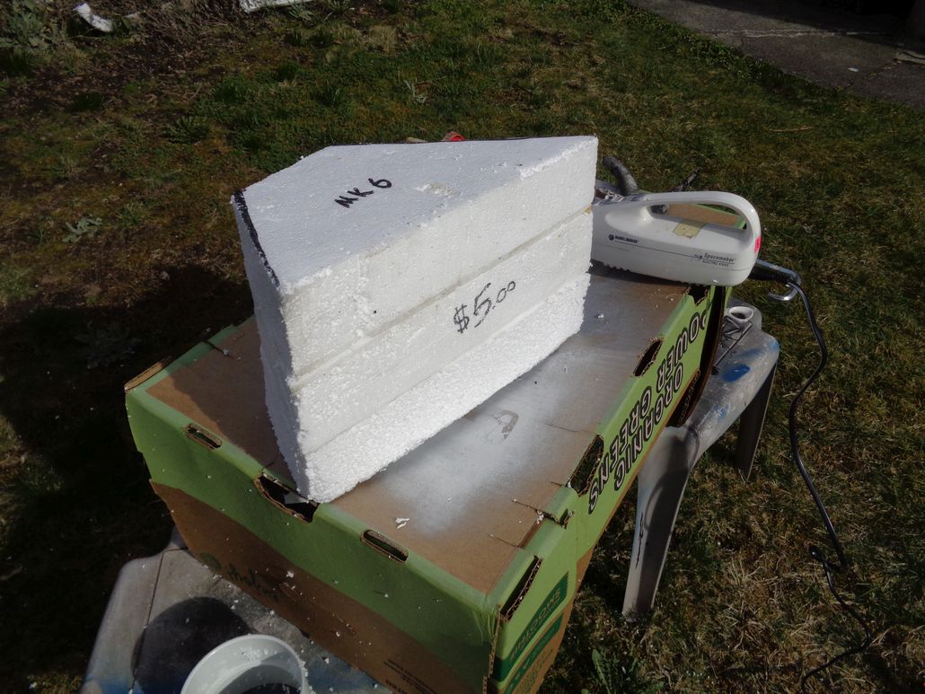
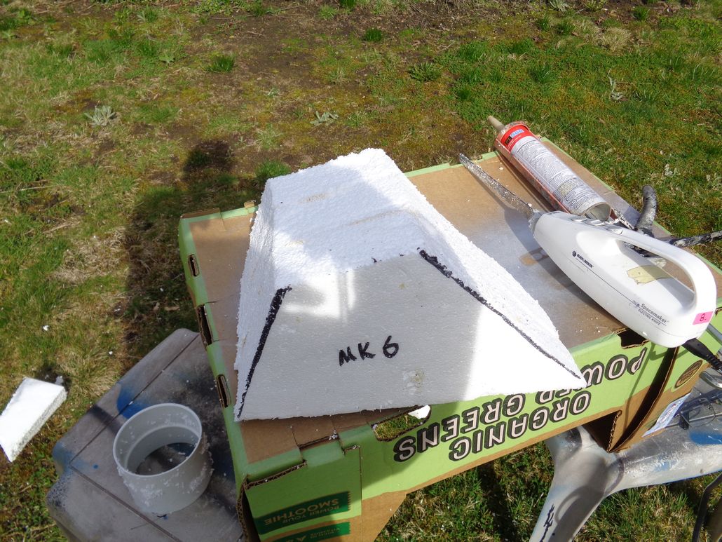
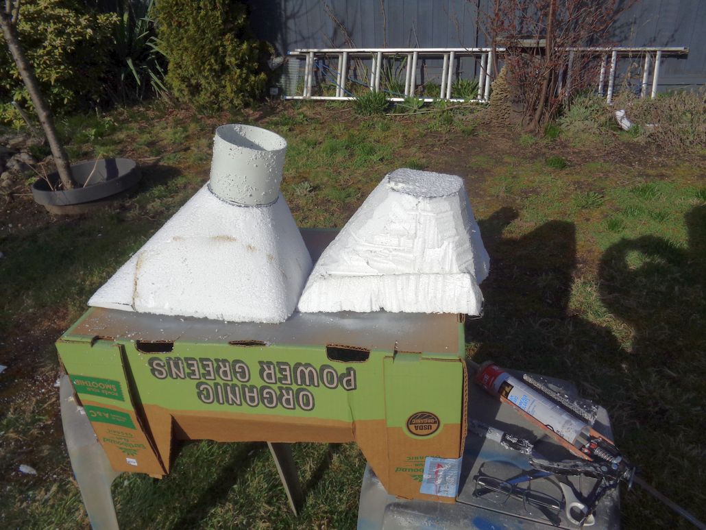
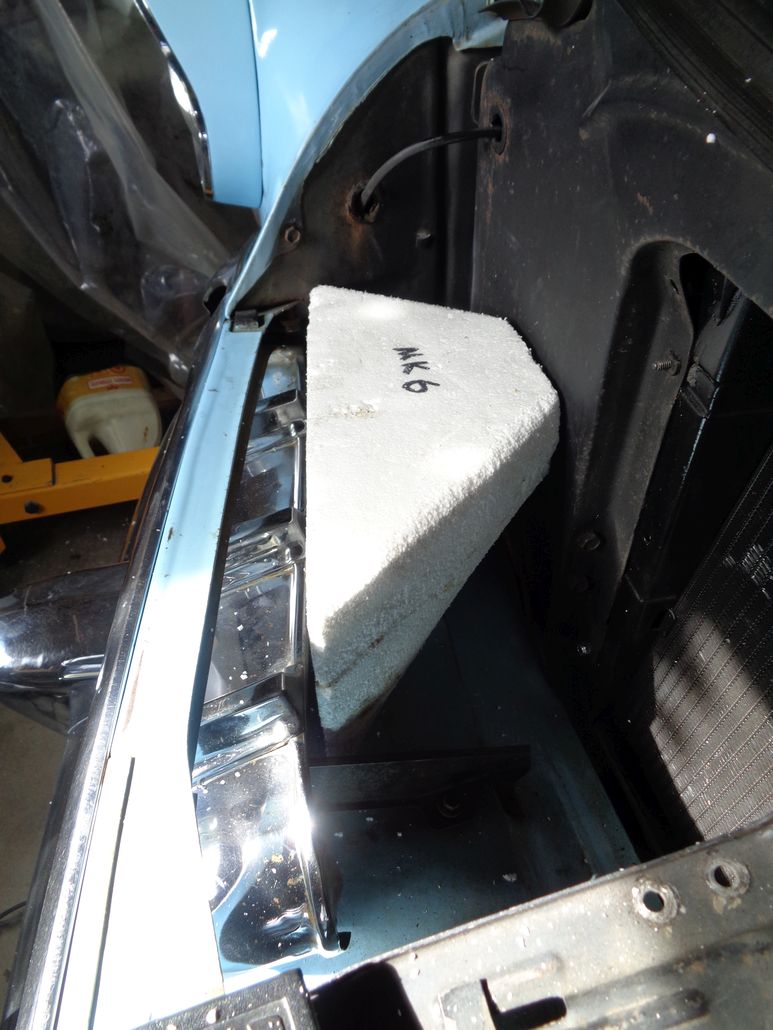
Location: Lower Mainland BC | MARK 6 SCOOP TRIAL
Bought some more foam and laminated three layers together with PL 300 Construction adhesive (the stuff that is made for foam - PL 400 eats foam - I learned that on a previous project).
Also bought a very used electric carving knife from Goodwill for $8 and after the glue had set up enough I went at it with the electric carving knife, the electric foam cutting "knife" and finally a hand held shaper. Worked outside. Bead board is nasty. I can't start my car until I a) vacuum up in the rad support area and b) get the air cleaner back on.
I made one mistake along the way today. I inadvertently cut too much on one corner. Solution was to patch in a new chunk of foam and re-cut and reshape.
The photos below show today's "progress". Once I get the signal light wire issue sorted, I will try the Mark 6 scoop in place. And then rework as needed. Then I hope to smooth the outside with something (perhaps "Concrete Fill") and then proceed to the fiberglassing stage.
 (Mark63LayerStartingBlock_1.jpg) (Mark63LayerStartingBlock_1.jpg)
 (Mark63LayerStartingBlock_2.jpg) (Mark63LayerStartingBlock_2.jpg)
 (Mark6BlockAfterShaping_1.jpg) (Mark6BlockAfterShaping_1.jpg)
 (Mark6BlockAfterShaping_2.jpg) (Mark6BlockAfterShaping_2.jpg)
 (Mark6BlockAfterShaping_3.jpg) (Mark6BlockAfterShaping_3.jpg)
 (Mark6BlockAfterShaping_4WIthMark5.jpg) (Mark6BlockAfterShaping_4WIthMark5.jpg)
Attachments
----------------
Mark63LayerStartingBlock_1.jpg (167KB - 504 downloads)
Mark63LayerStartingBlock_2.jpg (207KB - 517 downloads)
Mark6BlockAfterShaping_1.jpg (195KB - 533 downloads)
Mark6BlockAfterShaping_2.jpg (173KB - 516 downloads)
Mark6BlockAfterShaping_3.jpg (145KB - 523 downloads)
Mark6BlockAfterShaping_4WIthMark5.jpg (172KB - 512 downloads)
|
|
| |
|
Regular
Posts: 65
| Have you considered using a range hood adapter ? Seems like the would make one in the size you need and save you some time.
Somthing like this
https://www.homedepot.com/p/Speedi-Products-12-in-x-3-25-in-x-8-in-G... |
|
| |
|
Regular
Posts: 65
| This one would work too, since your hooking it up to a hose anyway
https://www.homedepot.com/p/Speedi-Products-14-in-x-3-25-in-x-8-in-W... |
|
| |
|
Expert 5K+
Posts: 9900
Location: Lower Mainland BC |
Sorry, you obviously didn't start at the top of this page. I've already considered and tried such HVAC pre-made tin boots. They're too "Rat Rod" for my tastes, even if they worked (too small). What I am doing is more work but the final product won't embarrass me (hopefully).
I'm using this YouTube video as my guide:
https://www.youtube.com/watch?v=8QQPRb8CHmA
But thanks for the suggestion.
My previous trial:

Edited by 56D500boy 2018-03-30 1:49 AM
|
|
| |
|
Expert 5K+
Posts: 9900
Location: Lower Mainland BC | Spent part of the afternoon polishing sill plates so I could finalize my carpet project and get the carpet held down. When I got tried of that, I went back to the air scoop project.
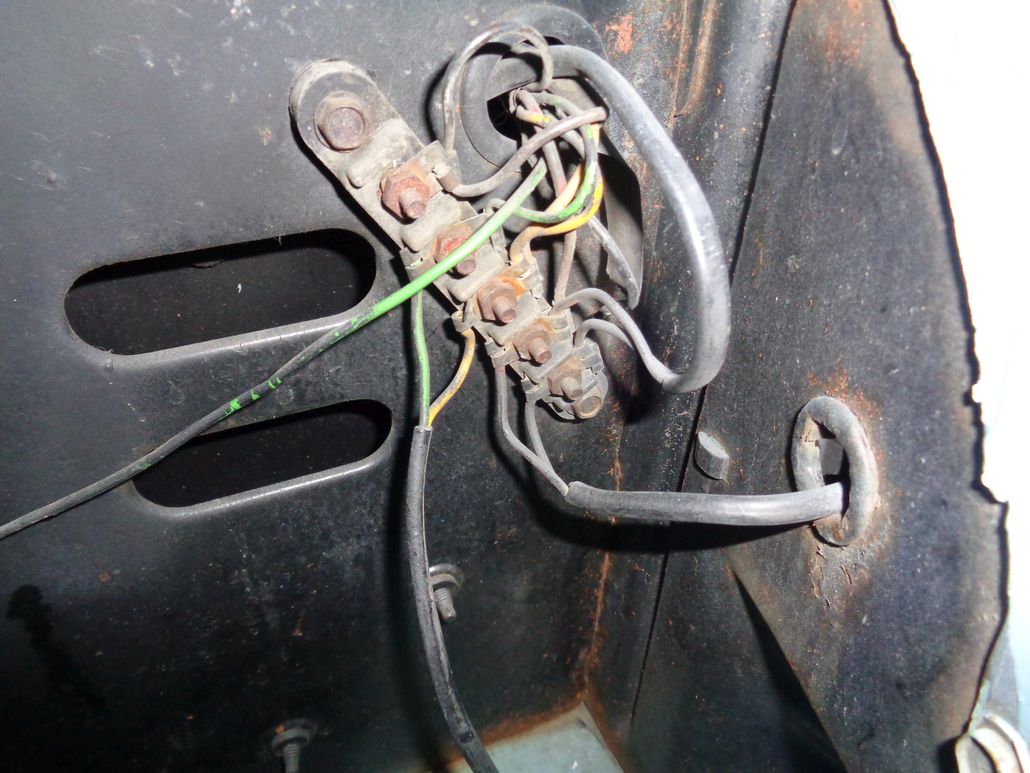
The first thing to do was to re-route the right park/signal light wiring so it didn't interfere with the scoop. The way the factory routed the wire was dumb (IMO). So, being a FL noob in most ways, and coming from a 93-94 Audi background, I figured that I just needed to get at the back of the signal/park light housing and disconnect the wiring there and re-route it. Sounds like a plan until I realize that I'm going to have to remove the housing from the grill bar to get at the back of the housing. Then it snowballs when I realize to do that I will have to remove the grill bar, at least enough so I can pull it out and expose the nuts or whatever at the back of the park/signal light housing.
Well about 30 minutes and probably 8 nuts/bolts later have the grill bar loose enough to remove the light housing. *THEN* I realize that there is no connector there to disconnect. Oh man. The can of worms that I opened. Now I have to de-rust the back of the grill bar and paint it. And paint the brackets. And de-rust the nuts and bolts. And clean up and paint the fender behind the end of the grill bar (minor surface rust). I can't put anything back unless I improve it. That is my mantra.
FINALLY, FINALLY, it hits me in the face. Hey idiot!! Follow that signal/park light wiring back! Maybe there is a connector. NOPE. No connector. BUT (and this is going to be no surprise to the non-noobs), there is a termination block on the rad support and you can disconnect wiring there and then re-route it at the right fender end. D'OH!!
I even previously posted the wiring diagram below (so I can't plead ignorance). Looks like I need to find the yellow and brown wires and temporarily disconnect them. Oh well, I learned something and my car will be better when I put that grill bar back after painting the backside of it and its brackets.

Edited by 56D500boy 2018-03-30 9:22 PM
|
|
| |
|
Expert 5K+
Posts: 9900
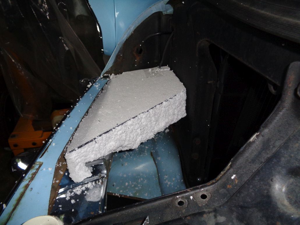
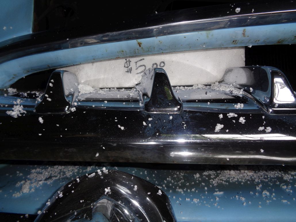
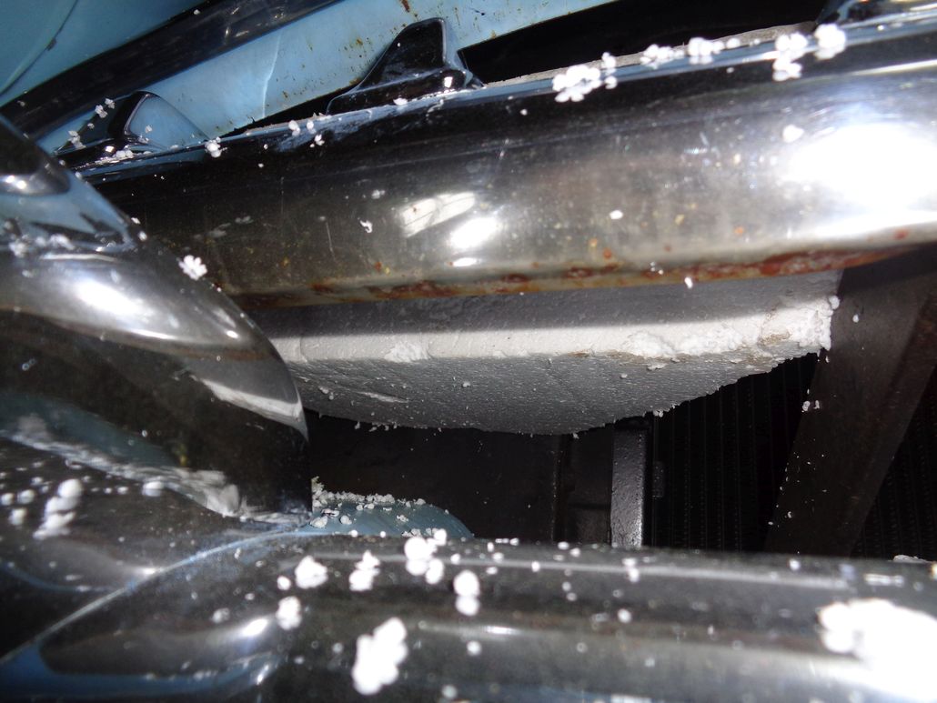
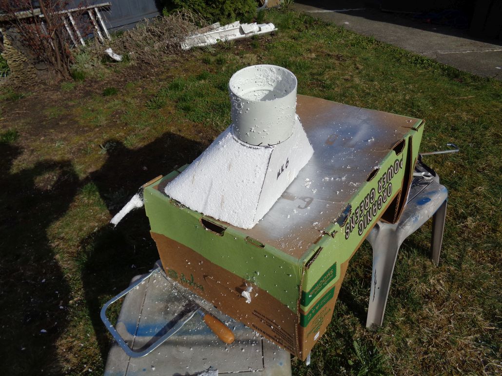
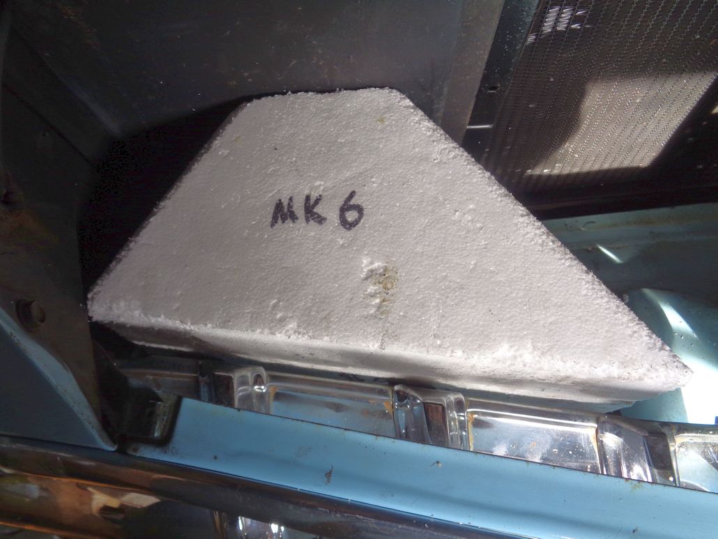
Location: Lower Mainland BC | You'll see why I am calling it "Committment Day" further down.
Started off the day disconnecting the Yellow and brown wires to the right parking/signal light at the terminal bar. This allowed me to pull the wires off the top of the rad support and then pull it through the rad support and get it out of the tanglement at the grill bar. With that wire out of the way, I then could try the Mark 6 foam form for fitment.
I am quite happy with the result. I will have to add a bit of foam at the top to accommodate the "pipe" connection (Schedule 10 PVC coupler) that, even at its lowest point is still higher than the top of the Mark 6 form. No biggy. I had already mentally allowed for about 1/2" rise on the top when I marked the back of the form for shaping. Turns out that it might be more like an inch. Still no biggy.
Then I removed the grill bar completely so I had access to the rad support. I placed the PVC coupler on the engine bay side of the rad support and marked a point at the top where I could drill a pilot hole. Once I had the pilot hole drilled and had a reference point to work from, I placed the coupler in position on the grill side of the rad support and then scribed the circumference of the coupler on the rad support. The I drilled a larger pilot hole, big enough to get the metal blade of my Bosch jig-saw through the hole. At that point I was pretty much committed to this project. As soon as I started cutting the hole with my jig saw, I was really committed.
Turns out at I would have never been able to do any of this cutting if I had figured out the wiring issue and had NOT removed the grill bar. I needed the grill bar out in order get enough room for the jig saw. Even then I ran into issues and was only able to use the jig saw to cut between 12 oclock and 10 oclock (anti-clockwise) and from about 6 to 4 oClock (anti-clockwise). Then I ran into impediments with the jig saw.
I needed another solution (smaller jig saw?) but I wasn't about to go out and buy another tool. Instead I got out my trusty Dremel and loaded it with an E-Z-Load reinforced cut off disk. Then I carefully ran the cut-off wheel (at about 4 out of 5 on the variable speed) around the inside of the scribe line. I was surprised that I had the steadiness to do that but I did. About 20 minutes and one blade change later, I had a 4"+ hole cut out. A little cleaning with a plug stone on my angle grinder and it was done.
Not shown in the photos below, I subsequently sanded the edges of the hole and painted the entire right section of the rad support with Tremclad semi-gloss black. I will sand it a bit tomorrow and give it another coat before moving on.
 (56DodgeRadSupportTerminalStrip_Before.jpg) (56DodgeRadSupportTerminalStrip_Before.jpg)
 (Mark6InPlaceWithoutWiringIssue_1.jpg) (Mark6InPlaceWithoutWiringIssue_1.jpg)
 (Mark6InPlaceWithoutWiringIssue_2.jpg) (Mark6InPlaceWithoutWiringIssue_2.jpg)
 (Mark6InPlaceWithoutWiringIssue_Front_1.jpg) (Mark6InPlaceWithoutWiringIssue_Front_1.jpg)
 (Mark6InPlaceWithoutWiringIssue_Front_2.jpg) (Mark6InPlaceWithoutWiringIssue_Front_2.jpg)
 (Mark6InPlaceWithoutWiringIssue_Front_3.jpg) (Mark6InPlaceWithoutWiringIssue_Front_3.jpg)
 (Mark6Commitment_Schedule10HoleInRadSupport_1.jpg) (Mark6Commitment_Schedule10HoleInRadSupport_1.jpg)
 (Mark6Commitment_Schedule10HoleInRadSupport_2.jpg) (Mark6Commitment_Schedule10HoleInRadSupport_2.jpg)
 (Mark6Commitment_Schedule10HoleInRadSupport_3.jpg) (Mark6Commitment_Schedule10HoleInRadSupport_3.jpg)
 (Mark6Commitment_Schedule10HoleInRadSupport_4.jpg) (Mark6Commitment_Schedule10HoleInRadSupport_4.jpg)
Attachments
----------------
56DodgeRadSupportTerminalStrip_Before.jpg (143KB - 516 downloads)
Mark6InPlaceWithoutWiringIssue_1.jpg (140KB - 536 downloads)
Mark6InPlaceWithoutWiringIssue_2.jpg (123KB - 545 downloads)
Mark6InPlaceWithoutWiringIssue_Front_1.jpg (136KB - 503 downloads)
Mark6InPlaceWithoutWiringIssue_Front_2.jpg (98KB - 514 downloads)
Mark6InPlaceWithoutWiringIssue_Front_3.jpg (129KB - 522 downloads)
Mark6Commitment_Schedule10HoleInRadSupport_1.jpg (127KB - 516 downloads)
Mark6Commitment_Schedule10HoleInRadSupport_2.jpg (151KB - 499 downloads)
Mark6Commitment_Schedule10HoleInRadSupport_3.jpg (137KB - 511 downloads)
Mark6Commitment_Schedule10HoleInRadSupport_4.jpg (84KB - 508 downloads)
|
|
| |
|
Expert 5K+
Posts: 9900
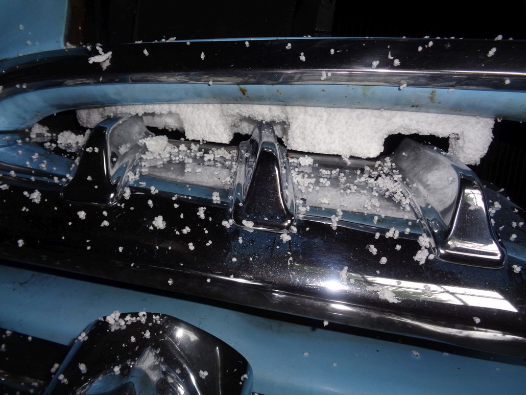
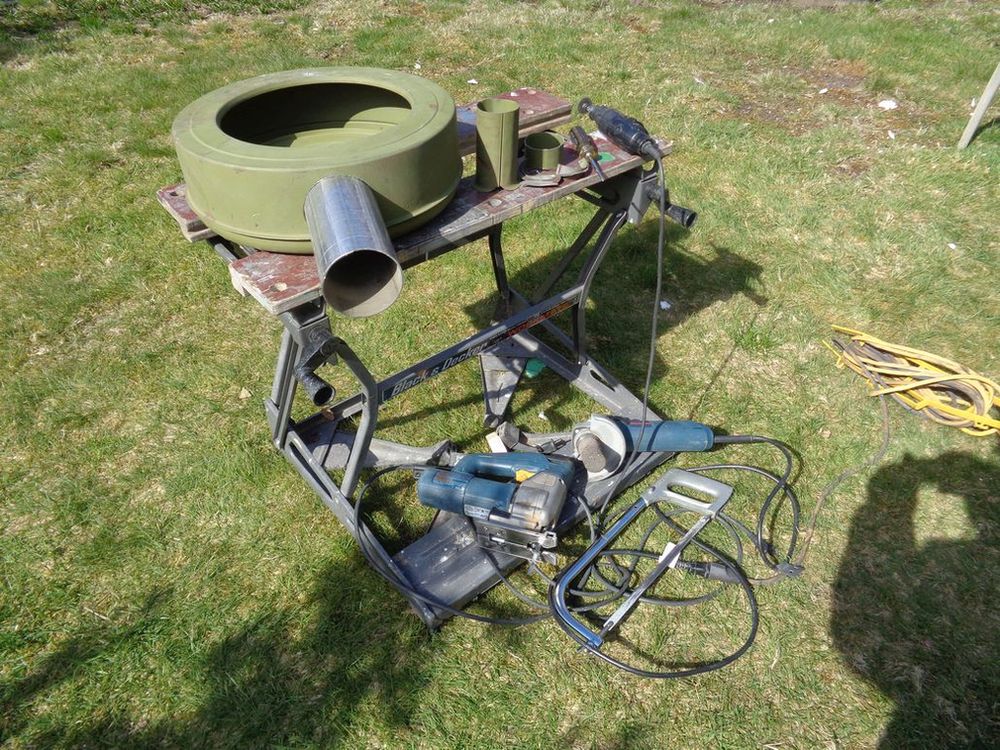
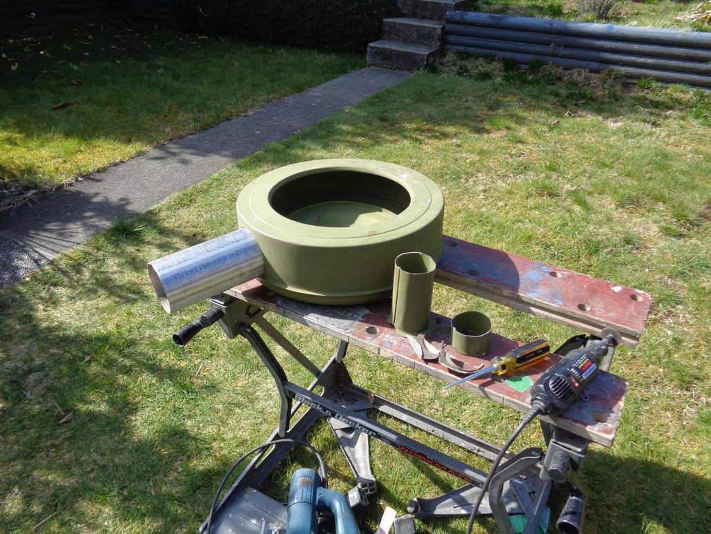
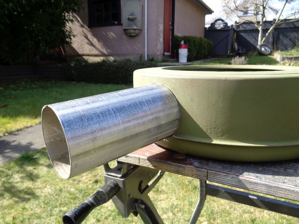
Location: Lower Mainland BC | Since probably before I even bought the green eBay Golden Lion air cleaner shell, I knew that the snorkel was going to be too small for my plan(s). So the other day I bought a couple of pieces of 3.5" OD Pipe that I could work with. The first one had an 1/8" wall thickness - likely too thick. Then I went to my friendly local muffler shop and got a piece of 14 gauge 3.5" exhaust pipe. (Cost me $8).
When I got home I show these to my metal fabricator-by-trade neighbour and he suggested using the exhaust pipe and scribing it to the metal can. That was the other day.
I had some time while some primer was drying on the car (behind the right grill bar), so I started the removal of the old snorkel.
This is what I started with:

I used my Dremel with a cut-off wheel to cut off a section of crimped joint between the upper and lower halves of the air cleaner shell. That allowed me to get the exhaust pipe closer to the shell and make the initial scribes. I thought I would be using the Dremel to cut the hole but it was too awkward on the small radius. SO I used my hacksaw to remove as much of the snorkel as possible. That allowed me to use my Bosch jig saw (with metal blade) to cut the initial scribed hole (staying on the inside as much as possible).
With that material out, I rescribed the hole to the exhaust pipe and started using my angle grinder and plug stone to grind away the unwanted material. Many tries and re-scribing. Slowly slowly and oops the exhaust pipe slipped into the hole. I am quite pleased with the fit.
Now I need to get it tacked in place and welded to the shell. Might be a bit tricky. Will cost me a case of beer.
Today's fun:
Edited by 56D500boy 2018-04-02 6:30 PM
 (GoldenLionAirCleanerSnorkelMod_1.jpg) (GoldenLionAirCleanerSnorkelMod_1.jpg)
 (GoldenLionAirCleanerSnorkelMod_2.jpg) (GoldenLionAirCleanerSnorkelMod_2.jpg)
 (GoldenLionAirCleanerSnorkelMod_3.jpg) (GoldenLionAirCleanerSnorkelMod_3.jpg)
 (GoldenLionAirCleanerSnorkelMod_4_annotated.jpg) (GoldenLionAirCleanerSnorkelMod_4_annotated.jpg)
Attachments
----------------
GoldenLionAirCleanerSnorkelMod_1.jpg (244KB - 497 downloads)
GoldenLionAirCleanerSnorkelMod_2.jpg (232KB - 506 downloads)
GoldenLionAirCleanerSnorkelMod_3.jpg (143KB - 503 downloads)
GoldenLionAirCleanerSnorkelMod_4_annotated.jpg (190KB - 512 downloads)
|
|
| |
|
Expert 5K+
Posts: 9664
Location: So. Cal | I thought you were going to do 2 snorkels. That 3.5" size is much better.
Edited by Powerflite 2018-04-02 7:43 PM
|
|
| |
|
Expert 5K+
Posts: 9900
Location: Lower Mainland BC | Powerflite - 2018-04-02 7:42 PM
I thought you were going to do 2 snorkels. That 3.5" size is much better.
I gave up on the two snorkel idea a while ago. The location of the battery and wiring on the left side and my reluctance to go through the fender liners like Sid did in Germany killed that idea. As a result a single snorkel was the answer. I then set about to find a 383/413 Golden Lion air cleaner because of the throat size (4 7/32") would work on my WCFB carb. The 3.5" diameter for the new snorkel is about as big as I can go.
I've been cleaning up and painting in the right front side where the grill bar is located. I needed the grill bar out to cut the 4"+ hole in the rad support and while it was out, I decided to "betterify (tm)" the areas that the grill bar hides because I'm not going to want to go back in there later.
Painting is 99% done and drying (two small glitches to fix tomorrow). And then I can start the reassembly and the final mods on the Mark 6 air scoop foam core prior to starting to lay up fiberglass and resin.
|
|
| |
|
Expert 5K+
Posts: 9900
Location: Lower Mainland BC | Got through with the grill bar rehab (enough for now anyway) and the painting in the area between the rad support and the grill bar (and a bit of the side fender). Put the grill bar back in and moved the park/signal light wire out of the way (the previous location was making it impossible for me to try the Mark 6 scoop in place properly).
With the wires out of the way and the Mark 6 foam scoop form in position, I see that there need to be a Mark 7 with a bit more added at the top to match the 4" hole I cut in the rad support, while leaving the base of the scoop sitting on the "gravel" pan between the rad support and the bumper. And probably some shaping at the bottom to move the exit up an inch or so.
Slowly Slowly.
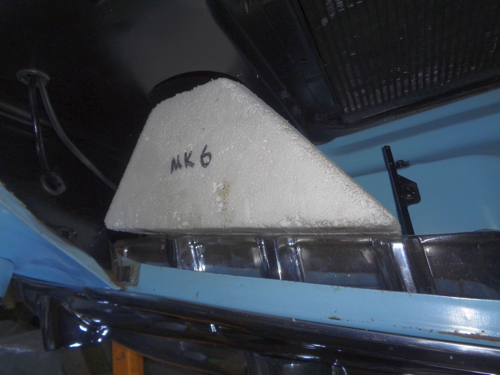 (Mark6InPlaceWithNoWireInterference_Above_1.jpg) (Mark6InPlaceWithNoWireInterference_Above_1.jpg)
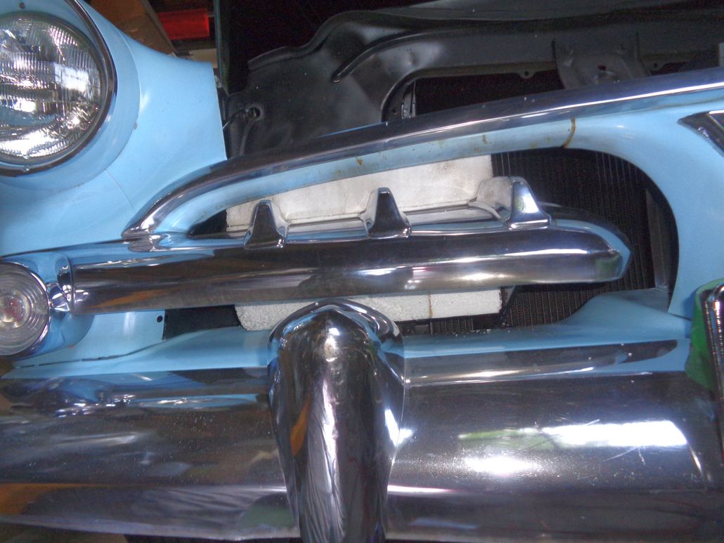 (Mark6InPlaceWithNoWireInterference_Front.jpg) (Mark6InPlaceWithNoWireInterference_Front.jpg)
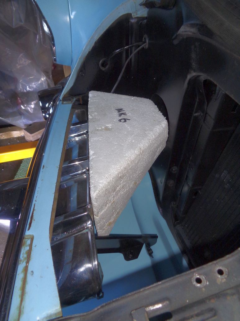 (Mark6InPlaceWithNoWireInterference_Side.jpg) (Mark6InPlaceWithNoWireInterference_Side.jpg)
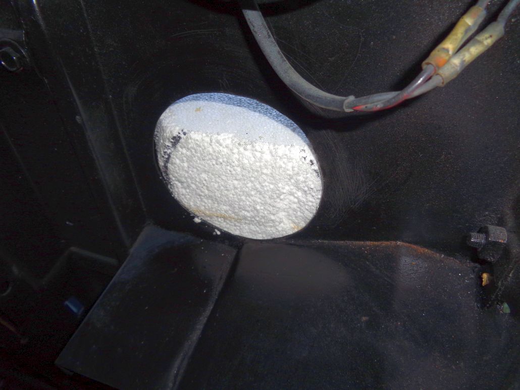 (Mark6InPlaceWithNoWireInterference_Back.jpg) (Mark6InPlaceWithNoWireInterference_Back.jpg)
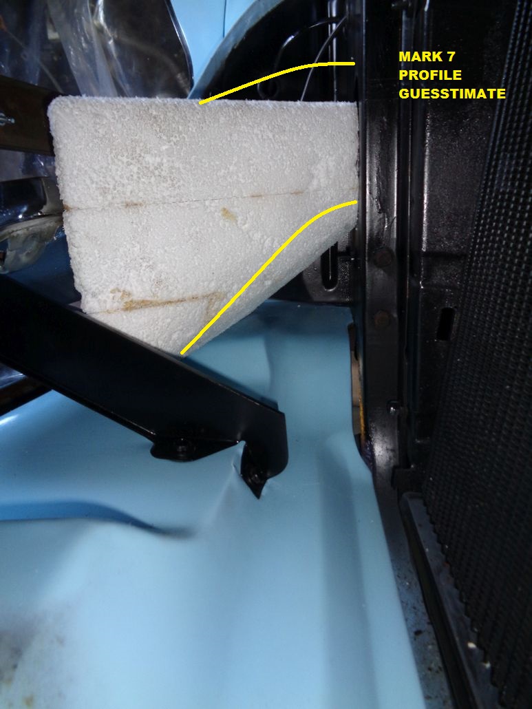 (Mark7ProfileEstimate_Annotated.jpg) (Mark7ProfileEstimate_Annotated.jpg)
Attachments
----------------
Mark6InPlaceWithNoWireInterference_Above_1.jpg (97KB - 517 downloads)
Mark6InPlaceWithNoWireInterference_Front.jpg (130KB - 520 downloads)
Mark6InPlaceWithNoWireInterference_Side.jpg (115KB - 516 downloads)
Mark6InPlaceWithNoWireInterference_Back.jpg (106KB - 530 downloads)
Mark7ProfileEstimate_Annotated.jpg (165KB - 516 downloads)
|
|
| |
|
Expert 5K+
Posts: 9900
Location: Lower Mainland BC | My last post included this guesstimate about what the Mark 7 scoop form might look like.

To get to Mark 7 from Mark 6, I added a partial layer on the back half(ish) of the top of the Mark 6 form. After the glue (PL 300 Construction FOAM board adhesive) set up, I started cutting away the excess, first with my $8 second hand store electric carving knife and then with my electric foam hot knife (more like a hot "rod" than a blade). Slowly it got to what I had imagined. Then I went at the form with my ancient Stanley Shure-form hand shaper/plane until I was happy with the general shape.
Then I bought some artists's Gesso (canvas primer) and painted the form with that and let it dry overnight. Then this morning, I put a thin layer of pre-mixed dry wall mud on the form, in hopes of creating a nice smooth surface. When it dried, I tried it in the car (looked promising) and then I started sanding it with 80 grit. After getting it pretty good, I put it back in the car and took some photos (see below). When I was done with the photos, I put a bit more dry wall mud on in areas that had imperfections that I wanted to eliminate. I will let that dry in the basement bathroom ("my" bathroom) with the electric baseboard heater cranked a bit. Tomorrow I will sand it one last time, and with luck (weatherwise), I will start putting the fiberglass on with epoxy resin.
I am using this video as my general guide on this scoop project.
https://www.youtube.com/watch?v=8QQPRb8CHmA
Today's photos:
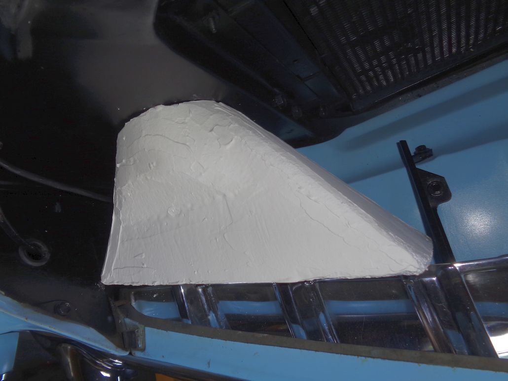 (Mark7ScoopFormFromAbove_BeforeSanding.jpg) (Mark7ScoopFormFromAbove_BeforeSanding.jpg)
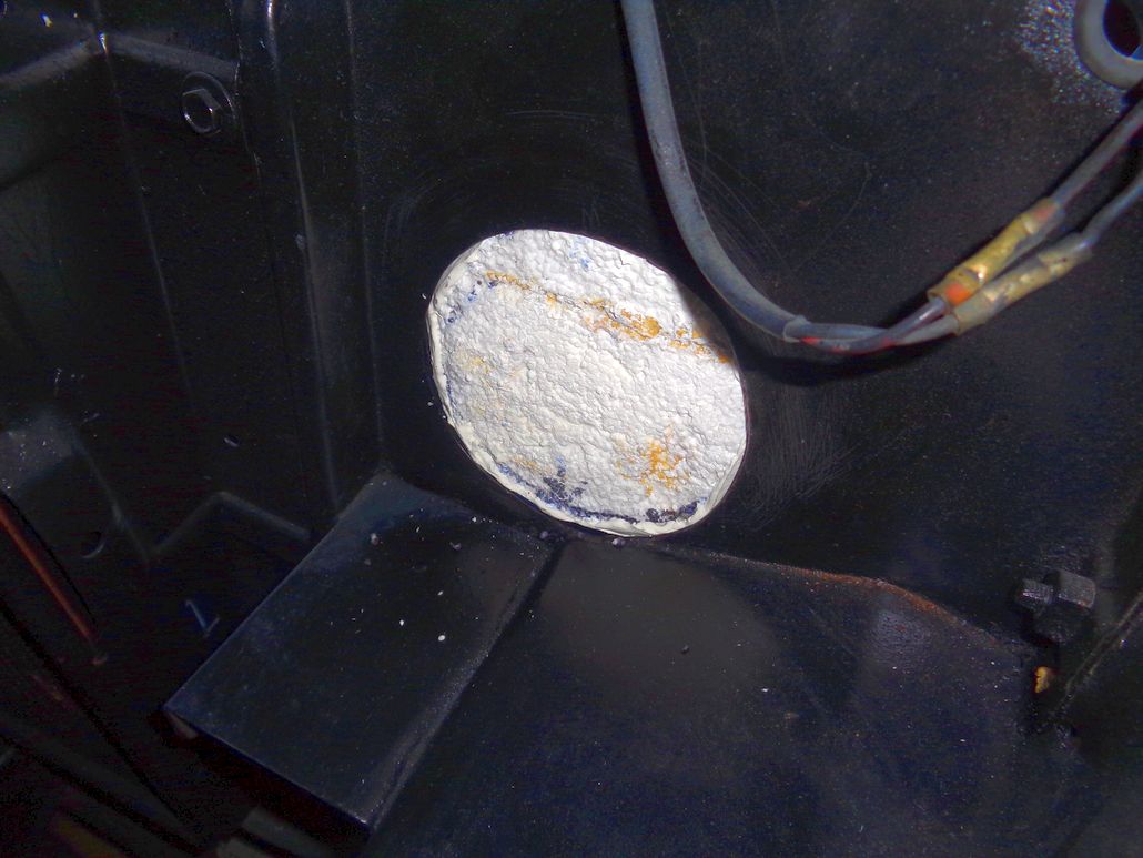 (Mark7ScoopFormFromEngineBaySide.jpg) (Mark7ScoopFormFromEngineBaySide.jpg)
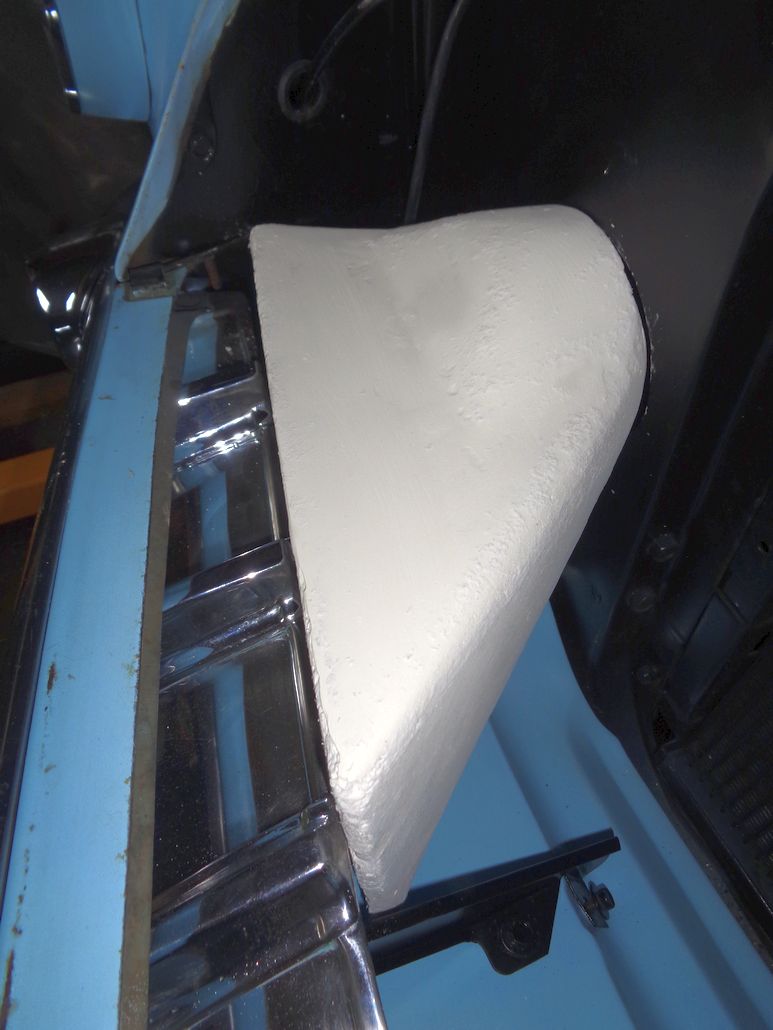 (Mark7ScoopFormFromAboveCenter_AfterSanding.jpg) (Mark7ScoopFormFromAboveCenter_AfterSanding.jpg)
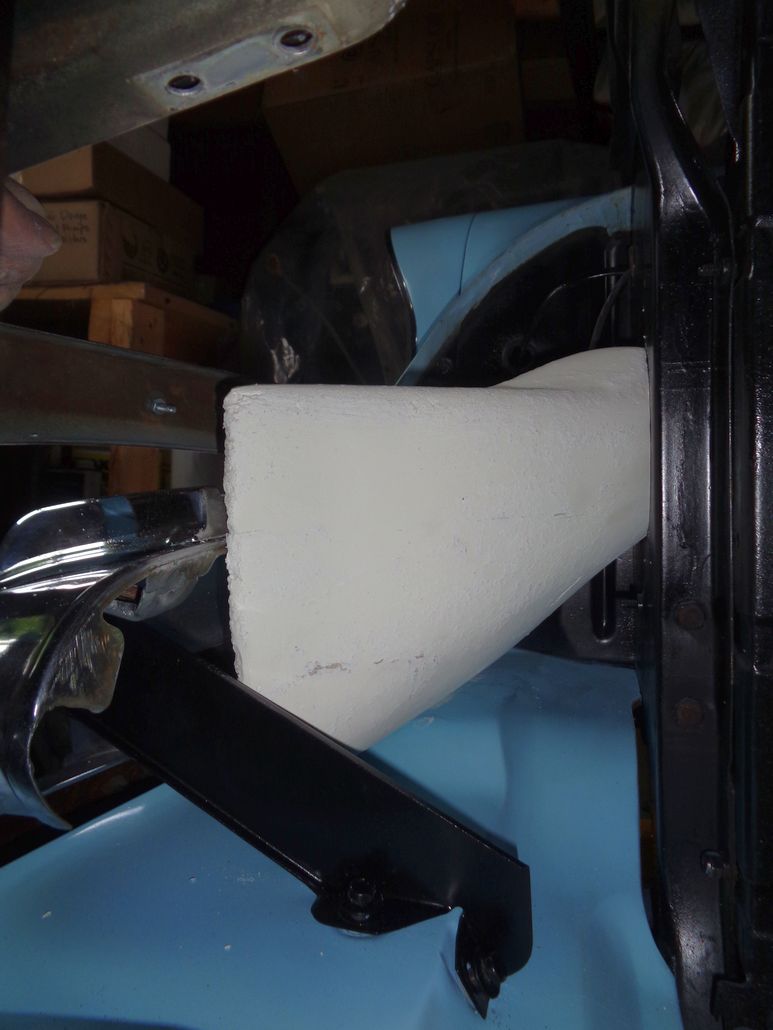 (Mark7ScoopFormFromSide_AfterSanding.jpg) (Mark7ScoopFormFromSide_AfterSanding.jpg)
Attachments
----------------
Mark7ScoopFormFromAbove_BeforeSanding.jpg (86KB - 534 downloads)
Mark7ScoopFormFromEngineBaySide.jpg (115KB - 506 downloads)
Mark7ScoopFormFromAboveCenter_AfterSanding.jpg (90KB - 507 downloads)
Mark7ScoopFormFromSide_AfterSanding.jpg (85KB - 509 downloads)
|
|
| |
|
Expert 5K+
Posts: 9900
Location: Lower Mainland BC | Guess what? The video I was following makes it look so much easier than reality. Who knew? LOL.
I had applied another thin layer of dry wall mud on the foam - just to fill in a few divots that I didn't like. After I sanded that off I decided today was the day that the epoxy resin and fibreglass cloth were going to meet the Mark 7 foam form. At the last minute, I panicked about making sure that the scoop would meet up with the PVC coupler properly and decided to glue-gun a coupler to the form. Bad idea - I am not very good with a glue gun. Turns out hot glue can't be easily smoothed, or ground or cut or anything. I did what I could including adding some masking tape to smooth the transition from the foam to the coupler. It's not pretty. I will only need about 1/2" of coupler going through the rad support (it was my template for scribing and cutting that hole) so it might turn out okay (and if it doesn't, its going to be painted black anyway - so most of the "sins" will be hidden).
I dry fitted a piece of fiberglass cloth and, without fully figuring things out (bad idea), I mixed up 6 oz of epoxy resin (4 oz of Part A and 2 oz of Part B). Then I started appling the mixed resin to the form where it was going to get cloth. Then I added the cloth and more resin, cutting away unneeded cloth with a pair of my wife's best scissors (That will be okay won't it??)(I kid). I didn't have the top of the form figured out before I started so when I got the bottom and the sides on, I cut another piece of cloth and applied it on top with overhangs down the side (about an inch). At least that is what I should have done. In reality I reused a section of the first piece that I had cut off and then tried to make it work. Not easy. Ended up cutting smaller pieces and adding them (with resin) to cover areas that my "patch" missed. Dumb idea. It's like I am using papier mache' techniques only in fibreglass and resin, not newspaper and paste. .
At this point I hope that I fix things on the next layer(s). Definitely use one piece for the top, not a lot of little pieces. Live and learn. Nothing ventured, nothing gained. It's not the mistakes you make, it's how you dispose of the witnesses.
Today's "mess" (the resin makes the fibreglass cloth completely transparent so you can see the masking tape that I put on to the foam and the PVC coupler):
Edited by 56D500boy 2018-04-10 11:13 AM
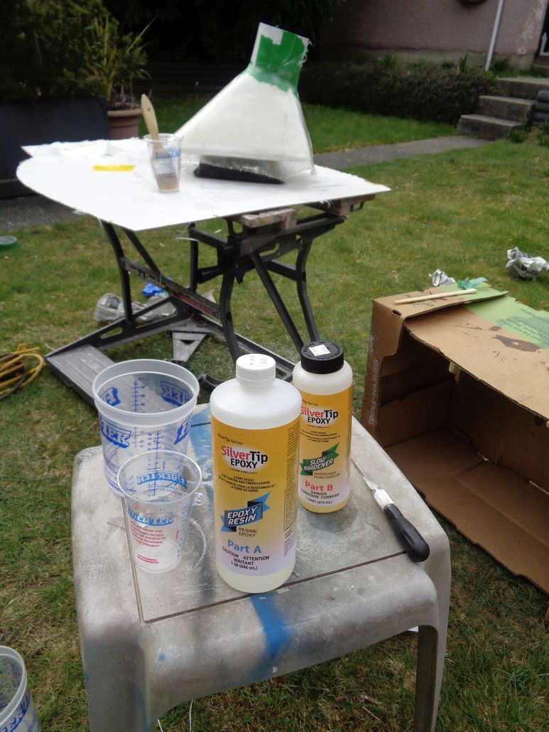 (Mark7ScoopGettingItsFirstLayerOfFibreglasAndEpoxyResin_1.jpg) (Mark7ScoopGettingItsFirstLayerOfFibreglasAndEpoxyResin_1.jpg)
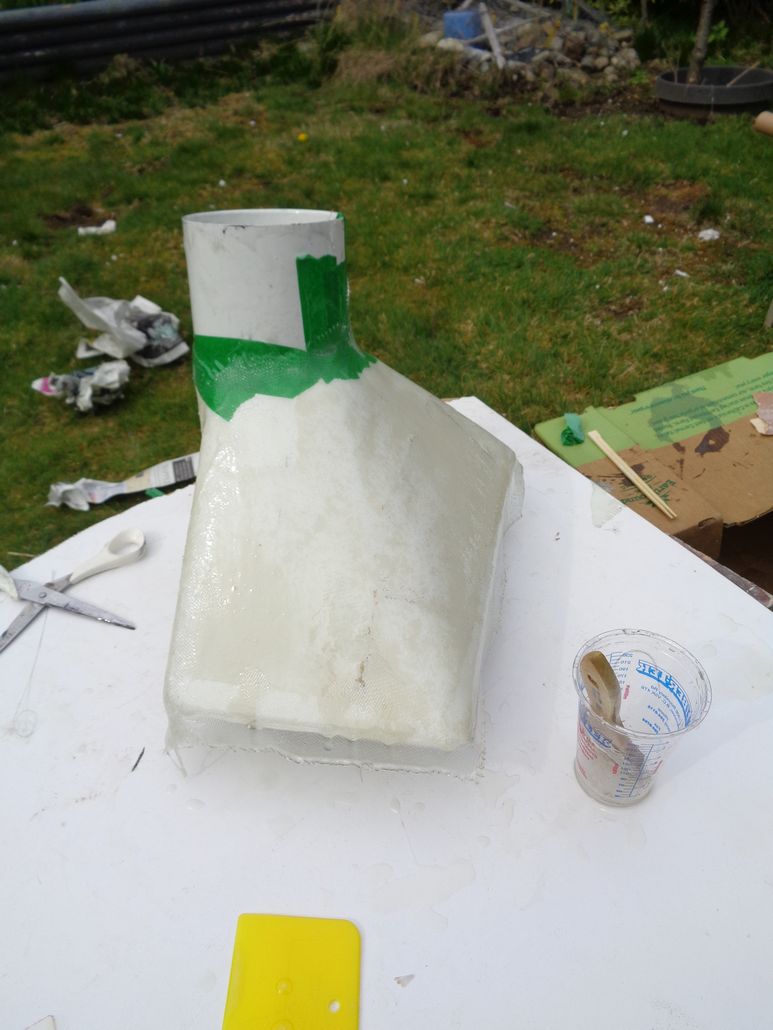 (Mark7ScoopGettingItsFirstLayerOfFibreglasAndEpoxyResin_2.jpg) (Mark7ScoopGettingItsFirstLayerOfFibreglasAndEpoxyResin_2.jpg)
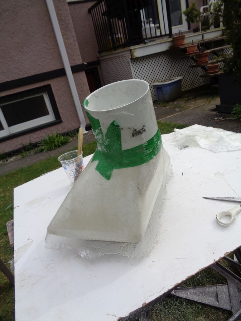 (Mark7ScoopGettingItsFirstLayerOfFibreglasAndEpoxyResin_3.jpg) (Mark7ScoopGettingItsFirstLayerOfFibreglasAndEpoxyResin_3.jpg)
Attachments
----------------
Mark7ScoopGettingItsFirstLayerOfFibreglasAndEpoxyResin_1.jpg (154KB - 516 downloads)
Mark7ScoopGettingItsFirstLayerOfFibreglasAndEpoxyResin_2.jpg (101KB - 505 downloads)
Mark7ScoopGettingItsFirstLayerOfFibreglasAndEpoxyResin_3.jpg (113KB - 514 downloads)
|
|
| |
|
Expert 5K+
Posts: 9900
Location: Lower Mainland BC | Not much to show but I did move on. I used the Dremel with a cut-off/grinding wheel and 100 grit sand paper to smooth off the first layer after it set up. For the second layer, I cut paper templates of the bottom and top of the scoop (with over laps) and once I was happy with them, I laid them on the raw fiberglass cloth and cut the two pieces. Then I mixed up 6 ounces (4 part A and 2 part B) of expoxy resin and laid on the second layer of fiberglass. Discovered that I probably put too much resin on because I got cloth movement and dripping. Live and learn. Today I ground and sanded the second layer and went and bought a pint of Part B hardener but this time "FAST". Cut the raw fibreglass cloth based on the paper template again and mixed up 4.5 oz of resin (3 of part A and 1.5 of part B - fast. Then I applied the third layer of fiberglass. I used push pins on the corners, sticking the pins through the wet fiberglass and into the foam to ensure that I have the cloth in the correct position. Faster set up and less material = less dripping and less (or no?) slippage of the cloth.
Tomorrow (or the next sunny day), I will sand/grind off the glitches in the 3rd layer and then apply a single layer of real carbon fiber cloth that I will give several coats of resin (over the next few days) to get the appropriate "depth".
Some photos tomorrow.
To |
|
| |
|
Expert 5K+
Posts: 9900
Location: Lower Mainland BC | 56D500boy - 2018-04-12 9:08 PM
Tomorrow (or the next sunny day), I will sand/grind off the glitches in the 3rd layer and then apply a single layer of real carbon fiber cloth that I will give several coats of resin (over the next few days) to get the appropriate "depth".
Rained yesterday so I worked on the rehab of the lighting terminal block in the garage.
Today was better. No rain so I could back at the air scoop.
Ground off the glitches in the 3rd layer of fiberglass and then sanded. Also trimmed off most of the sacrificial 4" PVC coupler, leaving about 1/2" to see if it and the rest of the scoop would fit back in the car. Nope. I am hoping that I can get down to 3/8" of coupler left - I just need a bit to feed through the hole that I cut in the rad support - then I will install a piece of 4" PVC from the engine bay side - maybe just friction fit.
Once I tried the scoop and failed to get the fit, I moved on to the carbon fibre (CF) layer. That stuff is NOT easy to work with, at least the wider weave CF cloth that I chose (there is a tighter weave but I didn't like the look of it). I got the CF on, in two parts, top and bottom. But once again, I probably added to much resin and the cloth wanted to drift due to gravity. Not sure why I can't do minimal resin, i.e. just enough to stick the CF to the fiberglass. Oh well. Live and learn. (I won't be doing this again though)
Today's photos (no CF photos yet).
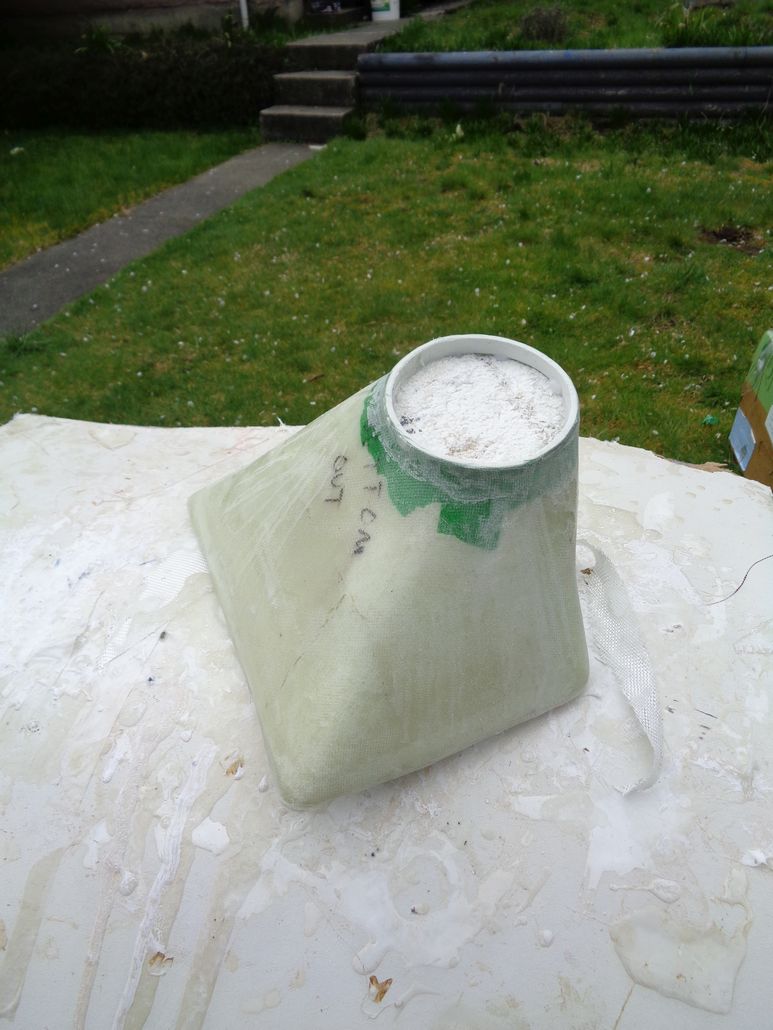 (Mark7After3rdLayerAndARoughTrim_1.jpg) (Mark7After3rdLayerAndARoughTrim_1.jpg)
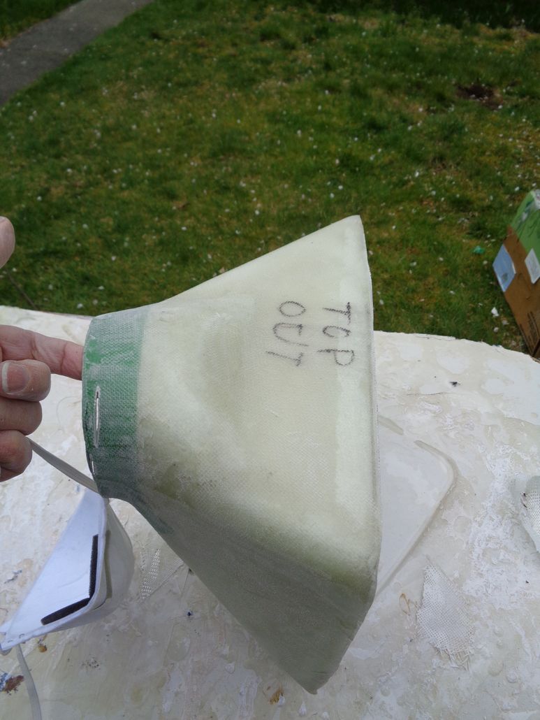 (Mark7After3rdLayerAndARoughTrim_2.jpg) (Mark7After3rdLayerAndARoughTrim_2.jpg)
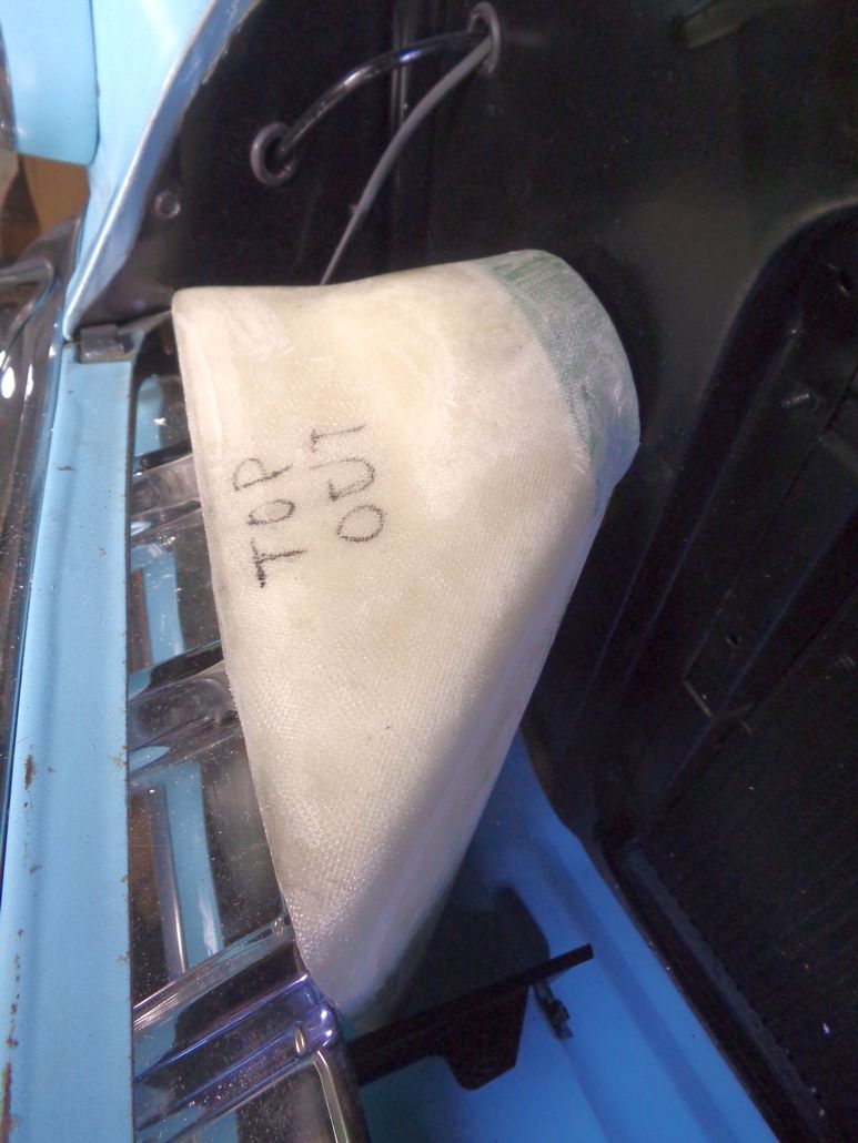 (Mark7After3rdLayerAndARoughTrim_TryingTheFit_1.jpg) (Mark7After3rdLayerAndARoughTrim_TryingTheFit_1.jpg)
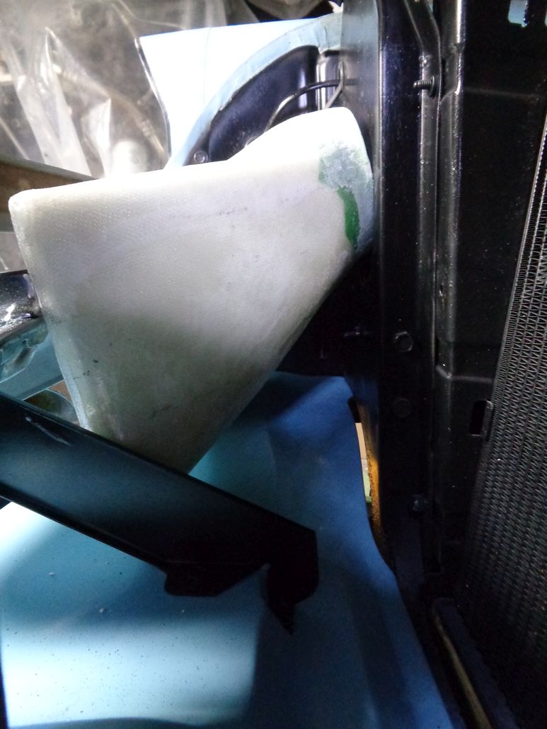 (Mark7After3rdLayerAndARoughTrim_TryingTheFit_2.jpg) (Mark7After3rdLayerAndARoughTrim_TryingTheFit_2.jpg)
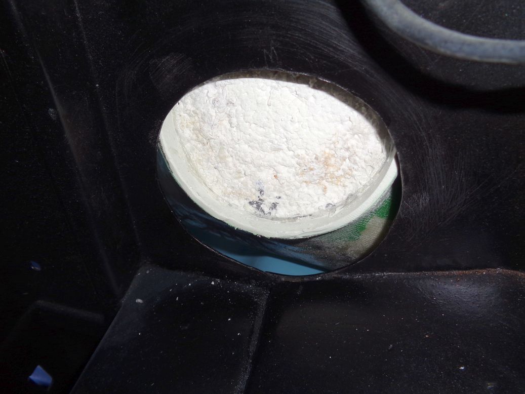 (Mark7After3rdLayerAndARoughTrim_TryingTheFit_3.jpg) (Mark7After3rdLayerAndARoughTrim_TryingTheFit_3.jpg)
Attachments
----------------
Mark7After3rdLayerAndARoughTrim_1.jpg (131KB - 463 downloads)
Mark7After3rdLayerAndARoughTrim_2.jpg (118KB - 472 downloads)
Mark7After3rdLayerAndARoughTrim_TryingTheFit_1.jpg (108KB - 472 downloads)
Mark7After3rdLayerAndARoughTrim_TryingTheFit_2.jpg (112KB - 484 downloads)
Mark7After3rdLayerAndARoughTrim_TryingTheFit_3.jpg (105KB - 470 downloads)
|
|
| |
|
Expert 5K+
Posts: 9900
Location: Lower Mainland BC | Okay. The Mark 7 with Carbon Fibre (CF) is in place (sort of).
I put the CF layer on the other day. New material. New mistakes (which I won't share ).
For some reason, even with the faster setting Part B epoxy resin, it took 2 or 3 days to cure up enough that I thought that I could trim it with my Dremel and the E-Z-Cut cutoff blade. I've only done a rough trim so far and will probably go at the edges with the belt sander. I trimmed about 1/8" off the PVC coupler (so now it is only about 3/8" deep) and that seemed to be enough to let me jam the Mark 7 into place for a trial. Not sure how easy it will be to get out. When I get it out I will need to grind away some of the resin around the PVC coupler ring to make the scoop fit better to the hole in the rad support.
I will do some more sanding, then gut the shell of the polystyrene bead foam form and then add another layer of resin. I don't think I will try to make it perfect because, it just isn't. Not bad for a first attempt. There won't be another attempt so what I get after another layer of just resin will be what it is.
Today's photos (car is outside while I continue to try to finalize the position of the carpet):
Edited by 56D500boy 2018-04-18 5:56 PM
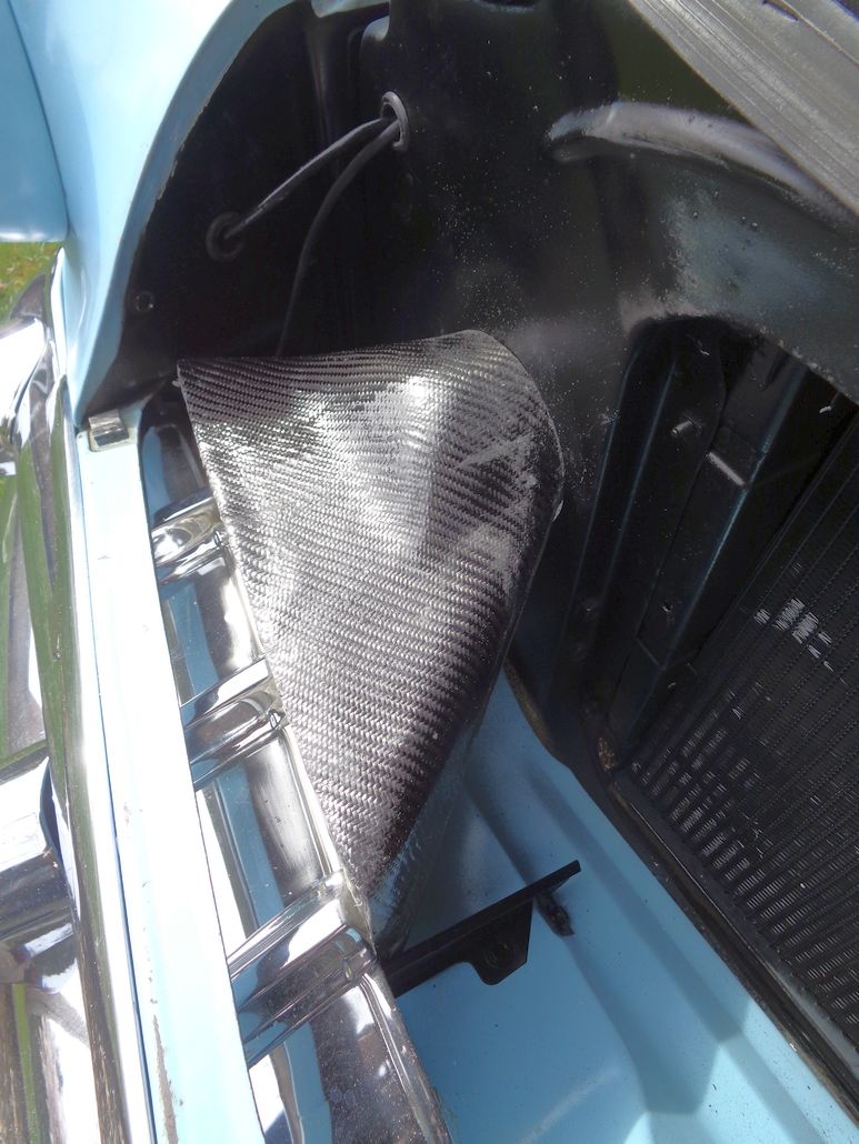 (Mark7WithOneLayerOfCarbonFiber_1.jpg) (Mark7WithOneLayerOfCarbonFiber_1.jpg)
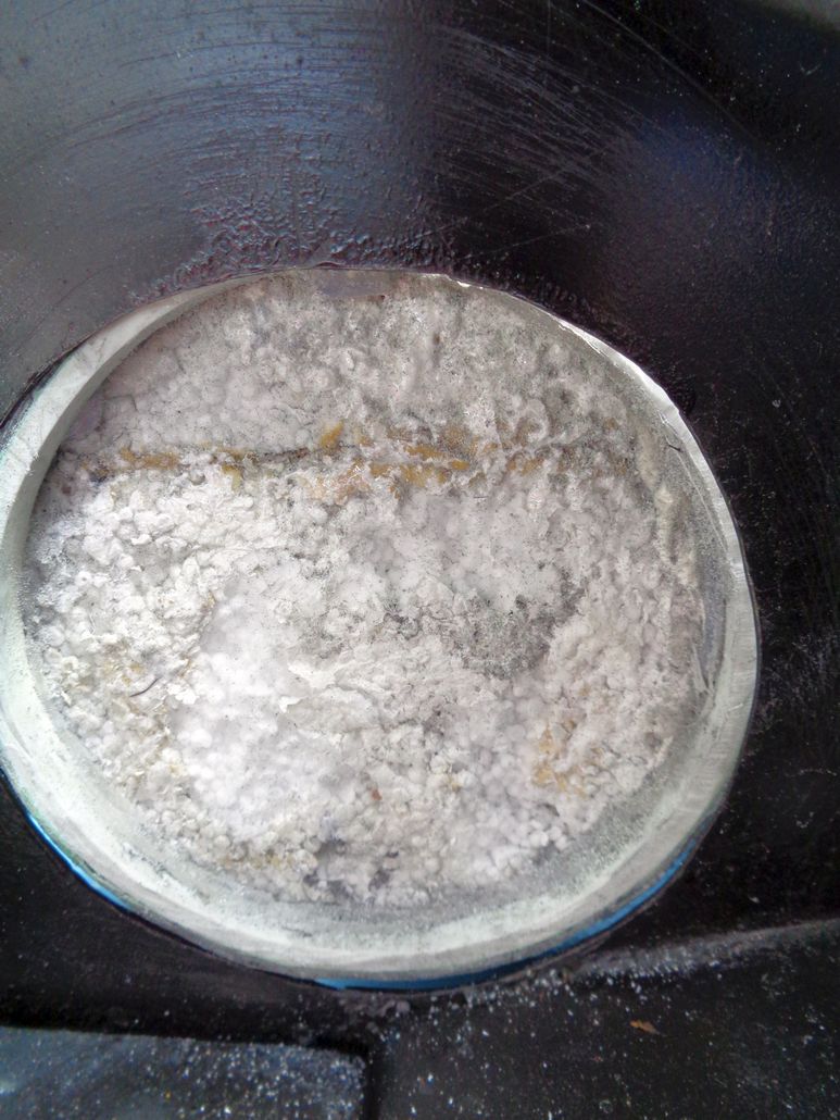 (Mark7WithOneLayerOfCarbonFiber_2.jpg) (Mark7WithOneLayerOfCarbonFiber_2.jpg)
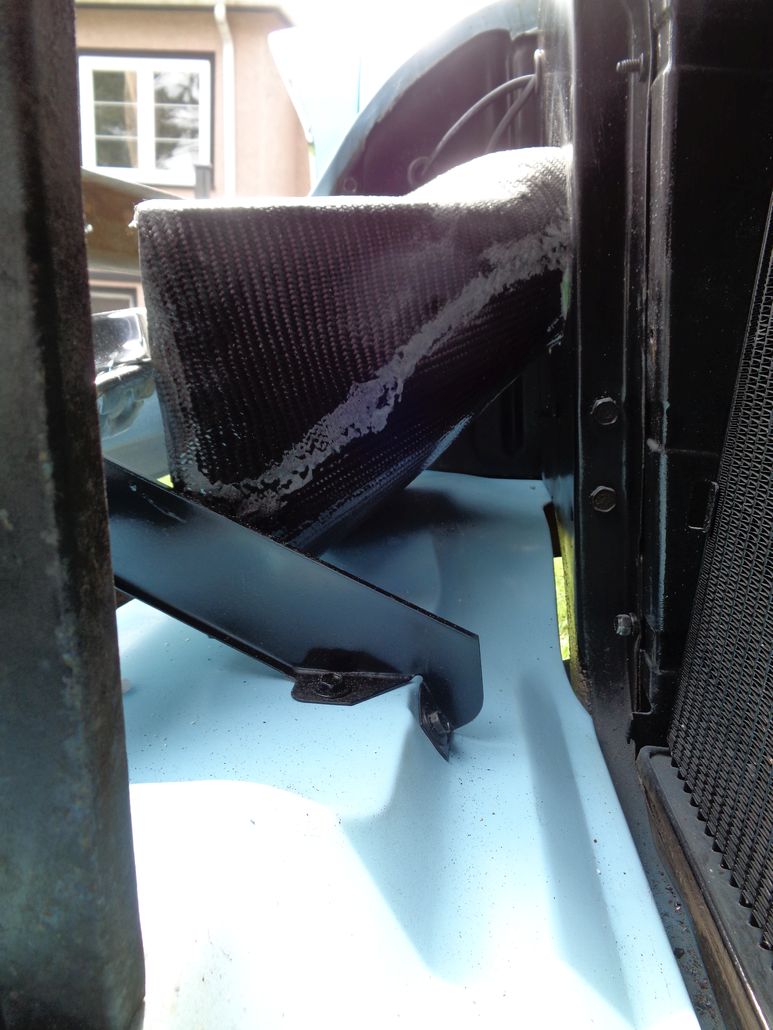 (Mark7WithOneLayerOfCarbonFiber_3.jpg) (Mark7WithOneLayerOfCarbonFiber_3.jpg)
Attachments
----------------
Mark7WithOneLayerOfCarbonFiber_1.jpg (159KB - 455 downloads)
Mark7WithOneLayerOfCarbonFiber_2.jpg (153KB - 451 downloads)
Mark7WithOneLayerOfCarbonFiber_3.jpg (122KB - 450 downloads)
|
|
| |
|
Expert
Posts: 3967
Location: DFW, TX | It's starting to look like something! Thanks for the (detailed ) updates. |
|
| |
|
Expert 5K+
Posts: 9900
Location: Lower Mainland BC | 57burb - 2018-04-19 4:14 PM
It's starting to look like something! Thanks for the (detailed ) updates.
Thanks. It's going to look pretty okay after the next and hopefully last coat of resin and a then some sanding and polishing.
But I need to get going on the modified air cleaner to make it all work.
I am in the process of selling one of my cars (93 Audi S4 sedan) and I am getting a bit distracted.
|
|
| |
|
Expert 5K+
Posts: 9900
Location: Lower Mainland BC | 56D500boy - 2018-04-19 8:13 PM
I am in the process of selling one of my cars (93 Audi S4 sedan) and I am getting a bit distracted.
:)
Okay. My 350 hp 1993 Audi S4 quattro sedan (probably capable of 160 mph because they could do 150 mph with the factory 227 hp)that I had for 2 months short of 20 years and put a lot of blood sweat and $$$ into sold. Bye.
Back to the 56 Dodge.
Been working on the carpet install which has meant working on the C and B pillar covers so I can hold the new windlace in place. Today while the new paint on the B-pillar covers was drying, I started to play with the air scoop.
Dug into the foam core and extracted about 85% of it. Then I trial fitted it again into the space between the rad support and the right grill bar. Fits better than I remembered. Plus a piece of 4" PVC fits perfectly into the remaining 1/2" of the 4" coupling that I left in the scoop. I need to cut that piece of 4" PVC shorter and paint it. I also need to totally remove the foam core (somehow), add a final coat of resin on the outside and finalize the 2 or 3 options that I have for an anti-squirrel grill in the front of the scoop.
Photos from today:
Edited by 56D500boy 2018-05-11 11:15 PM
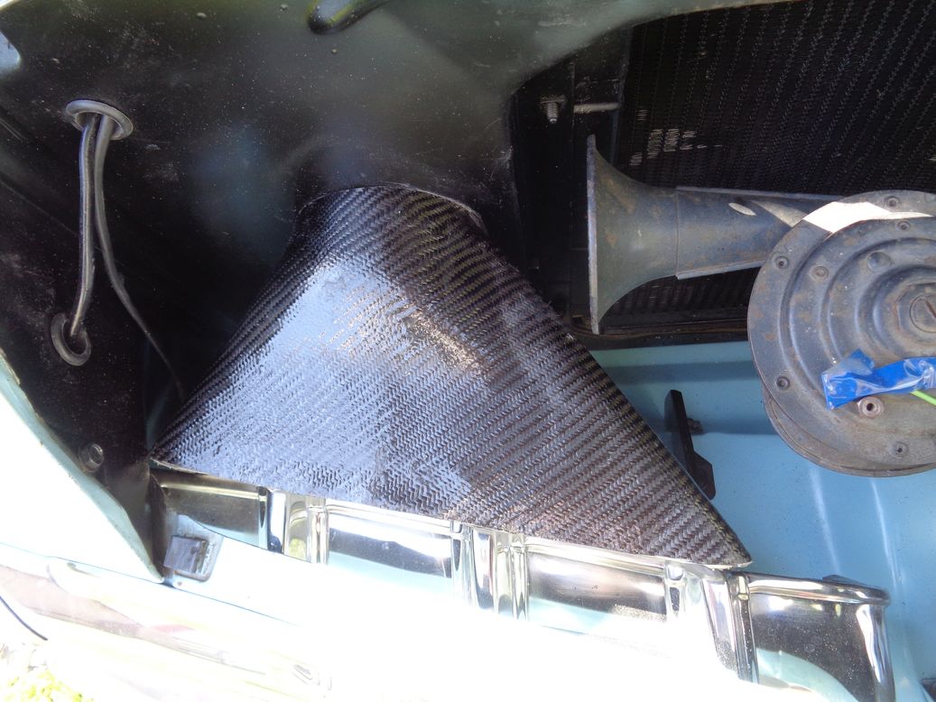 (Mark7ScoopFromAboveMay11_2018.jpg) (Mark7ScoopFromAboveMay11_2018.jpg)
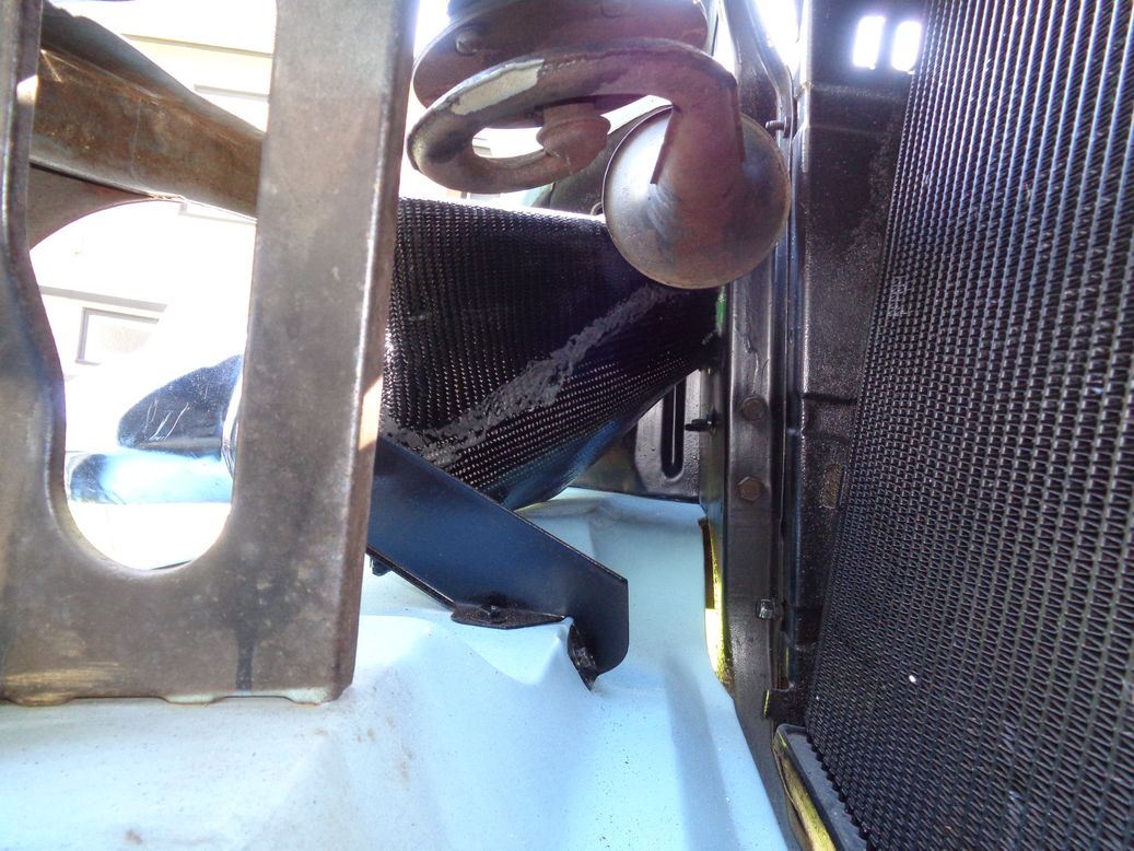 (Mark7ScoopFromSideMay11_2018.jpg) (Mark7ScoopFromSideMay11_2018.jpg)
 (Mark7ScoopFromFrontMay11_2018.jpg) (Mark7ScoopFromFrontMay11_2018.jpg)
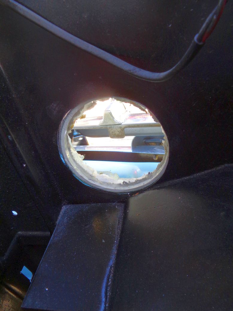 (Mark7ScoopFromEngineBayMay11_2018.jpg) (Mark7ScoopFromEngineBayMay11_2018.jpg)
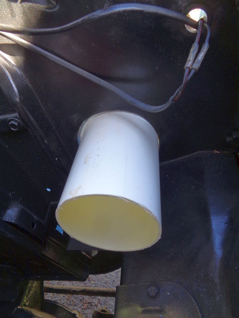 (Mark7ScoopFromEngineBayWith4inchPVCNippleMay11_2018.jpg) (Mark7ScoopFromEngineBayWith4inchPVCNippleMay11_2018.jpg)
Attachments
----------------
Mark7ScoopFromAboveMay11_2018.jpg (145KB - 691 downloads)
Mark7ScoopFromSideMay11_2018.jpg (172KB - 699 downloads)
Mark7ScoopFromFrontMay11_2018.jpg (170KB - 679 downloads)
Mark7ScoopFromEngineBayMay11_2018.jpg (103KB - 708 downloads)
Mark7ScoopFromEngineBayWith4inchPVCNippleMay11_2018.jpg (99KB - 671 downloads)
|
|
| |
|
Expert 5K+
Posts: 9664
Location: So. Cal | Now you need to paint the inside of it black to make it less visible from outside the car. |
|
| |
|
Expert 5K+
Posts: 9900
Location: Lower Mainland BC | Powerflite - 2018-05-12 1:24 AM
Now you need to paint the inside of it black to make it less visible from outside the car.
Absolutely. That was always part of "the Plan". Flat black yet. However, I can't do that until I get rid of all the white polystyrene beads. I've only used a 1" putty knife so far but will be getting out the big guns in the next few days. There is a possibility of Acetone being used.
We'll see.
I will post a photo when it is done, i.e. another coat of resin on the carbon fibre and maybe on the inside too.
Edited by 56D500boy 2018-05-12 1:40 AM
|
|
| |
|
Expert 5K+
Posts: 9900
Location: Lower Mainland BC | Previously I had found this advertisement from the August 1956 issue of Car Life:
Yesterday I bought a May 1956 Car Life magazine and there was an article about how to achieve 25 mpg and it featured the same cold air induction system. I see they definitely had a flapper/butterfly in the system.
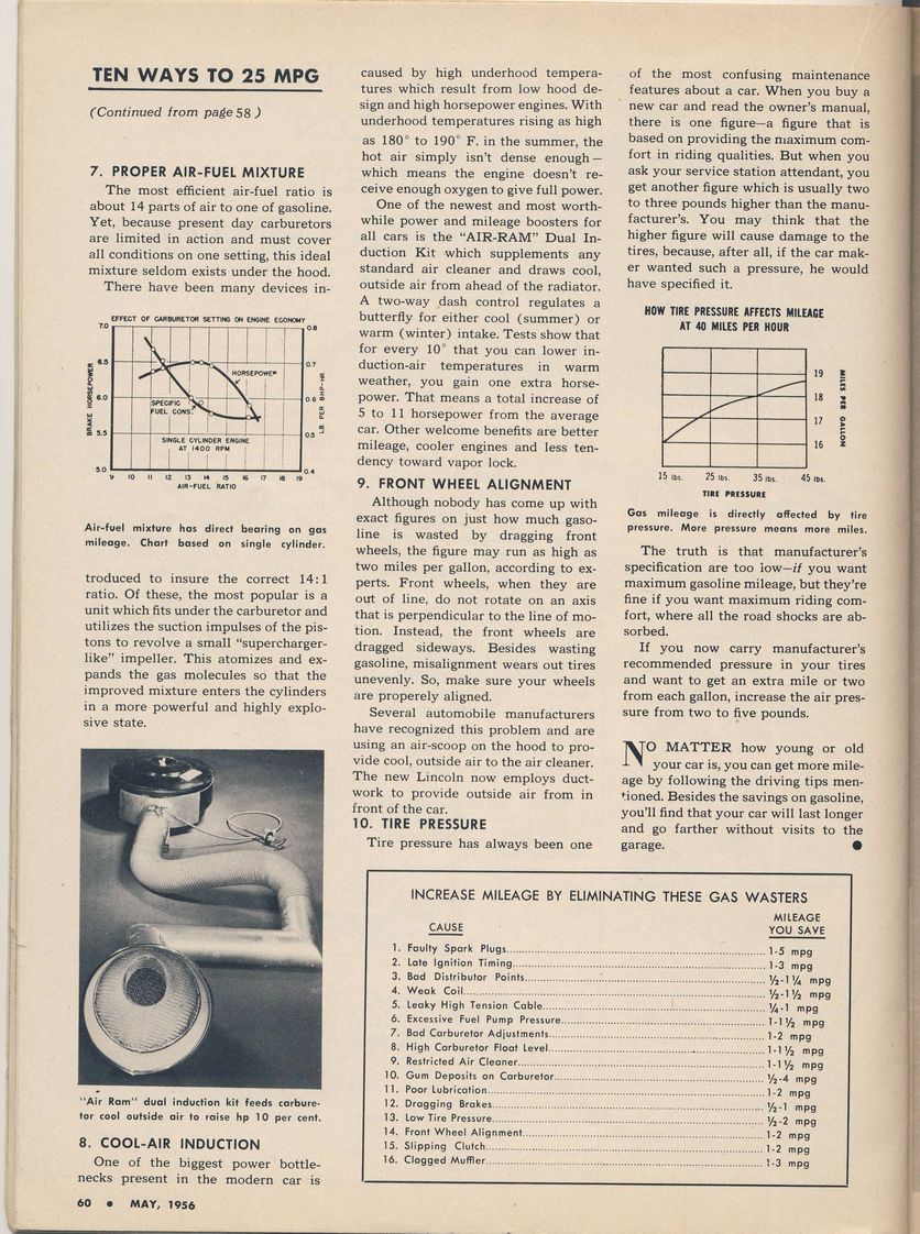 (CarLifeMay56_CoolAirInduction_small.jpg) (CarLifeMay56_CoolAirInduction_small.jpg)
Attachments
----------------
CarLifeMay56_CoolAirInduction_small.jpg (243KB - 686 downloads)
|
|
| |
|
Expert 5K+
Posts: 7400
Location: northern germany | Some of the old ads in the magazine are rubbish, this is not. Thanks for sharing. |
|
| |
|
Expert 5K+
Posts: 9900
Location: Lower Mainland BC | After recently finishing (98%) the conversion of an OE oil bath air cleaner to paper, I got back to this project. I've painted the modified Golden Lion filter with black crinkle paint (still drying - photos to come) and cleaning out the inside of the air scoop.
When I did the scoop plug, I should have covered the form with clear packing tape because the fiberglass resin did not stick to it and the resulting surface was shiny and smooth. But I didn't. So I have to deal with the resin getting in to the dry wall mud that I had applied in some areas as well as into the beaded part of the foam in other places. It was a bit of nightmare.
In the end after trying a bunch of mechanical means, scrapers, wire wheels, brushes, etc. what worked was my 20 year old Dremel and a die-grinder bit on medium speed, followed by wet sanding in our laundry sink with 220 grit paper. Then I dried it and painted it with a semi-gloss black paint. Not sure if I will add a coat of resin over that or not. Probably not. Outside, yes. Inside, no.
I tried the painted scoop in its location behind the right grill bar and it is very much hidden/stealth. Perfect.
Needs some final sanding/trimming on the inlet edge. I've added some JB Weld at the outlet end where the white PVC ring is "attached" to the fiberglass shell.
Some photos from today:
Edited by 56D500boy 2018-06-06 4:13 PM
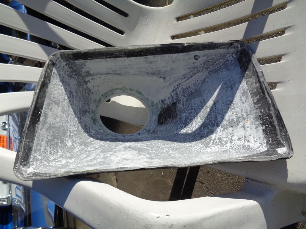 (AirScoopAfterTrimmingTheInteriorWithADremelDieGrinder_1.jpg) (AirScoopAfterTrimmingTheInteriorWithADremelDieGrinder_1.jpg)
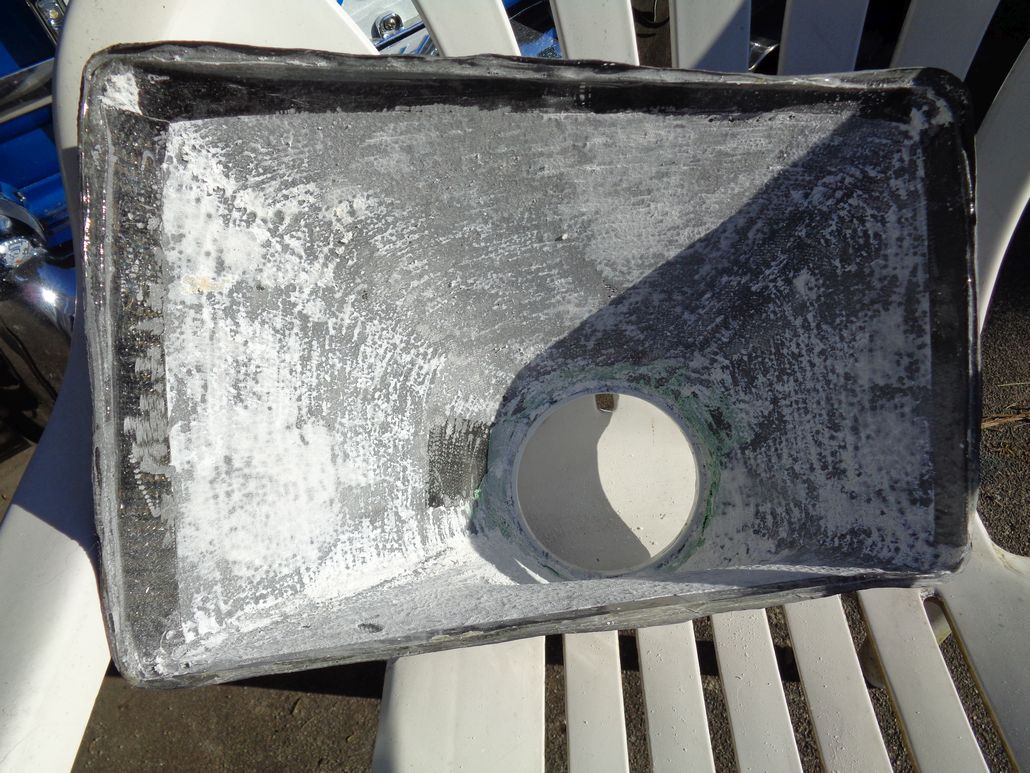 (AirScoopAfterTrimmingTheInteriorWithADremelDieGrinder_2.jpg) (AirScoopAfterTrimmingTheInteriorWithADremelDieGrinder_2.jpg)
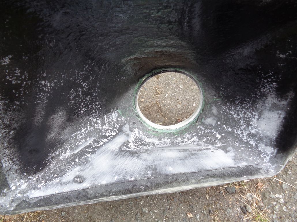 (AirScoopAfterTrimmingTheInteriorWithADremelDieGrinder_AndWetSandingWith220Grit.jpg) (AirScoopAfterTrimmingTheInteriorWithADremelDieGrinder_AndWetSandingWith220Grit.jpg)
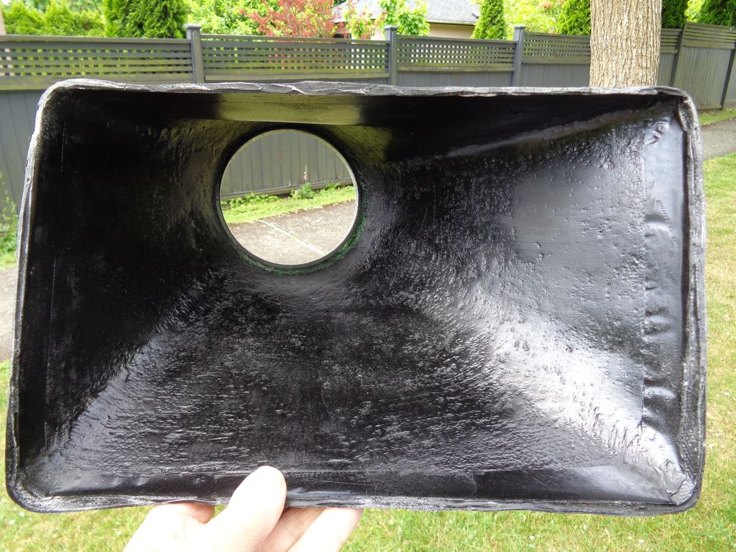 (AirScoopAfterTrimmingTheInteriorWithADremelDieGrinder_AndWetSandingWith220GritAndSemiGlossPaint.jpg) (AirScoopAfterTrimmingTheInteriorWithADremelDieGrinder_AndWetSandingWith220GritAndSemiGlossPaint.jpg)
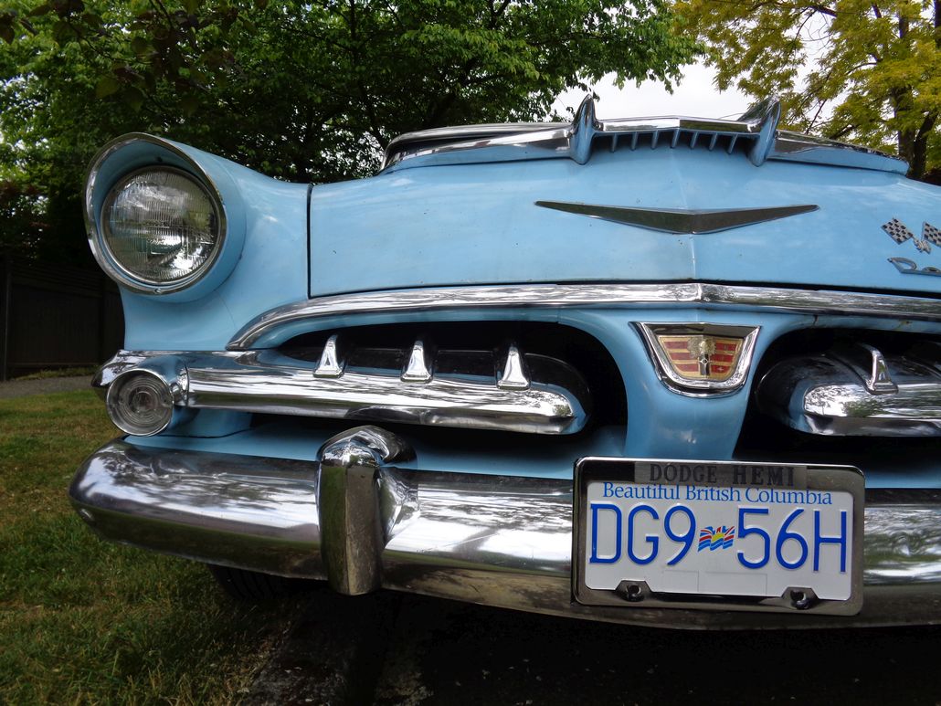 (AirScoopInPlaceWithSemiGlossBlackInteriorPaint.jpg) (AirScoopInPlaceWithSemiGlossBlackInteriorPaint.jpg)
Attachments
----------------
AirScoopAfterTrimmingTheInteriorWithADremelDieGrinder_1.jpg (147KB - 684 downloads)
AirScoopAfterTrimmingTheInteriorWithADremelDieGrinder_2.jpg (185KB - 667 downloads)
AirScoopAfterTrimmingTheInteriorWithADremelDieGrinder_AndWetSandingWith220Grit.jpg (178KB - 652 downloads)
AirScoopAfterTrimmingTheInteriorWithADremelDieGrinder_AndWetSandingWith220GritAndSemiGlossPaint.jpg (205KB - 678 downloads)
AirScoopInPlaceWithSemiGlossBlackInteriorPaint.jpg (181KB - 676 downloads)
|
|
| |
|
Expert 5K+
Posts: 9900
Location: Lower Mainland BC | Applied the "last" coat of resin on the outside of the air scoop this afternoon. While it was drying/curing, I cut the white PVC coupler down to a size that works as a spacer that leaves me about 3/8" between the bottom of the air cleaner and the top of the carburetor choke.
Trialled the modified Golden Lion air cleaner on the carb and discovered that I need a longer carb/air cleaner rod. Off to RONA (now owned by Lowes) to buy a stick of 1/4" x 20 thread ready rod. While I was there, I also picked up a 4" galvanized heating duct damper to put somewhere between the scoop and the air cleaner and a length of flexible dryer duct (the good kind).
When I got back, I cut an appropriate length of ready rod and mounted the air cleaner. Then I tried the flexible duct over the air cleaner snorkel. Oops. Needs a spacer/adapter. No problem. I had a black ABS reducer that was perfect size to fit over the snorkel and inside the flexi duct. (Luck or skill ?? LOL. LUCK). So I cut an adapter ring and gave it a light sanding. It will need more to fully fit over the snorkel. Fine for now.
I put the adapter ring on the end of the snorkel and tried the duct. Hmm....Snorkel is a bit long. *IF* I want to include the damper in series between the scoop and the air cleaner, the snorkel is going to have to be about 3" or more shorter so the bend in the flexiduct isn't crazy. I can figure that out tomorrow. For today, I pushed the flexiduct further over the snorkel to see if there was some improvement. Some but it's going to need a hack saw on the snorkel.
Some photos from today:
Edited by 56D500boy 2018-06-06 9:22 PM
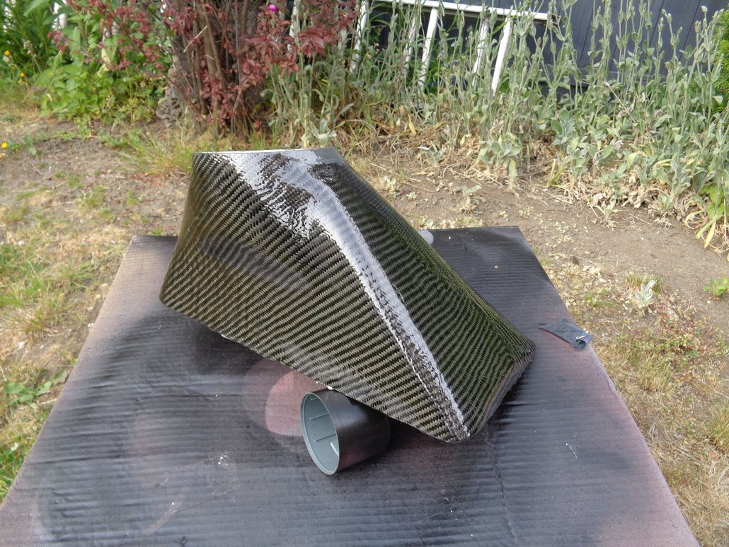 (LastCoatOfResinDryingOnAirScoop.jpg) (LastCoatOfResinDryingOnAirScoop.jpg)
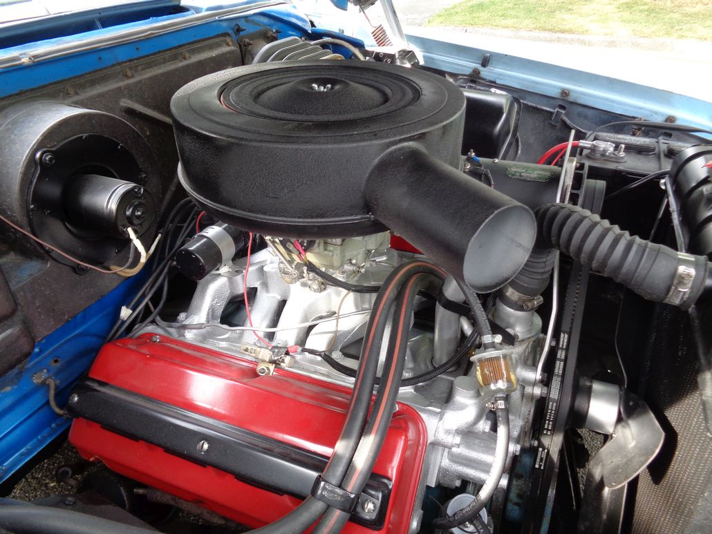 (ModifiedGoldenLionAirCleanerOn315Hemi.jpg) (ModifiedGoldenLionAirCleanerOn315Hemi.jpg)
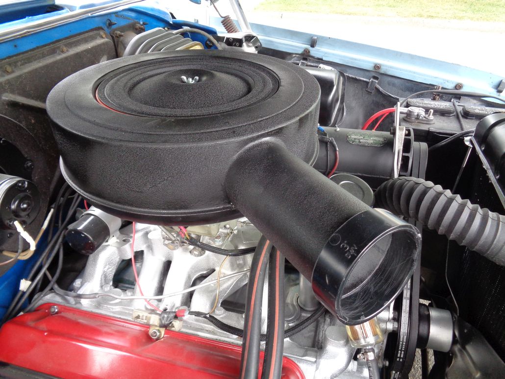 (ModifiedGoldenLionAirCleanerOn315Hemi_WithABSAirHoseAdapterRing.jpg) (ModifiedGoldenLionAirCleanerOn315Hemi_WithABSAirHoseAdapterRing.jpg)
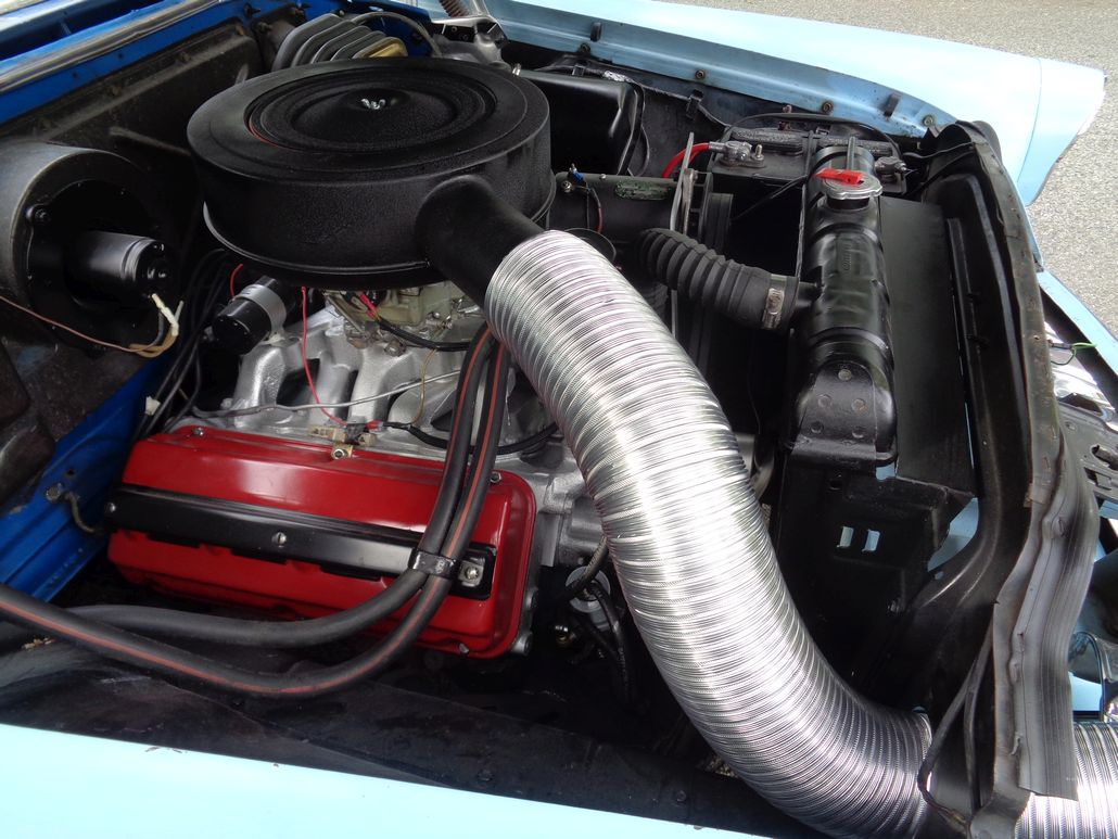 (ModifiedGoldenLionAirCleanerOn315Hemi_WithABSAirHoseAdapterRingAnd4InchFlexiDuct.jpg) (ModifiedGoldenLionAirCleanerOn315Hemi_WithABSAirHoseAdapterRingAnd4InchFlexiDuct.jpg)
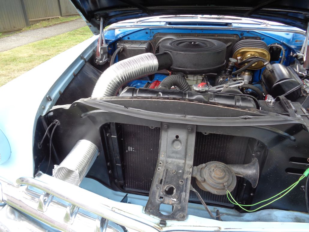 (ModifiedGoldenLionAirCleanerOn315Hemi_WithABSAirHoseAdapterRingAnd4InchFlexiDuct_PushedOnFurther.jpg) (ModifiedGoldenLionAirCleanerOn315Hemi_WithABSAirHoseAdapterRingAnd4InchFlexiDuct_PushedOnFurther.jpg)
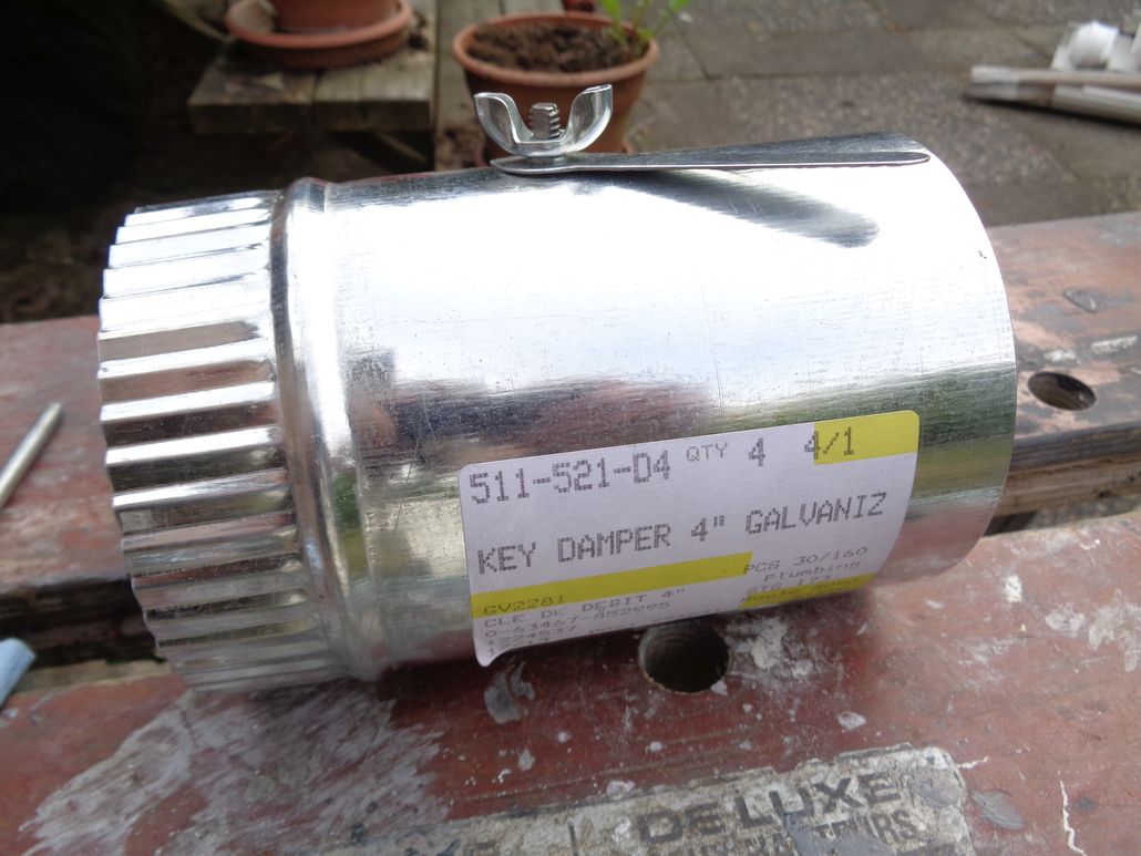 (Galvanized4InchFlowDamper_1.jpg) (Galvanized4InchFlowDamper_1.jpg)
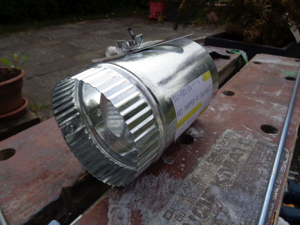 (Galvanized4InchFlowDamper_2.jpg) (Galvanized4InchFlowDamper_2.jpg)
Attachments
----------------
LastCoatOfResinDryingOnAirScoop.jpg (222KB - 680 downloads)
ModifiedGoldenLionAirCleanerOn315Hemi.jpg (167KB - 728 downloads)
ModifiedGoldenLionAirCleanerOn315Hemi_WithABSAirHoseAdapterRing.jpg (171KB - 680 downloads)
ModifiedGoldenLionAirCleanerOn315Hemi_WithABSAirHoseAdapterRingAnd4InchFlexiDuct.jpg (154KB - 657 downloads)
ModifiedGoldenLionAirCleanerOn315Hemi_WithABSAirHoseAdapterRingAnd4InchFlexiDuct_PushedOnFurther.jpg (161KB - 680 downloads)
Galvanized4InchFlowDamper_1.jpg (123KB - 674 downloads)
Galvanized4InchFlowDamper_2.jpg (130KB - 724 downloads)
|
|
| |
|
Expert 5K+
Posts: 9900
Location: Lower Mainland BC | After reviewing my photos, I find that 4" ducting looks ridiculous. Time to rethink and work with 3" ducting instead. Somehow.
AFTER reviewing my original plans, I see that I *WAS* going to use 3" ducting. Not sure when I let it morph to 4". No biggy. Back to Plan A = 3 inch.
Edited by 56D500boy 2018-06-07 2:07 AM
|
|
| |
|
Expert 5K+
Posts: 9900
Location: Lower Mainland BC | 56D500boy - 2018-06-06 11:21 PM
After reviewing my photos, I find that 4" ducting looks ridiculous. Time to rethink and work with 3" ducting instead. Somehow.
AFTER reviewing my original plans, I see that I *WAS* going to use 3" ducting. Not sure when I let it morph to 4". No biggy. Back to Plan A = 3 inch.
3" was the way to go.
I stopped at RONA (now owned by Lowes) and went through their plumbing and heating section looking for bits that I could cobble together to use 3" flexible hose. Turned out better than I expected.
As per the photo(s) below, I bought 3" semi-rigid aluminum ducting, a 3" galvanized round connector union, a 3" PVC to ABS adapter (SOC x SP) and a 4" x 3" PVC to ABS reducing adapter. The 3" galvanized union fits inside the flexible ducting and the flexible ducting fits inside the air cleaner snorkel. The only game was to cut down the PVC and ABS bits so they were shorted (long enough to get glued together but not much more). I still need to work on that 3" PVC to ABS adapter that the 3" galvanized union slips into. It could be shorter.
IF I am going to have a damper I will have to have it *IN* the snorkel. I need to work on that more.
For now, here are some photos of how it went together today (NOTE: 1. Yes, I need to replace my hood to rad support gasket 2. The white PVC spool piece that you can see in the last two photos will get painted semi-gloss or flat black and it will disappear):
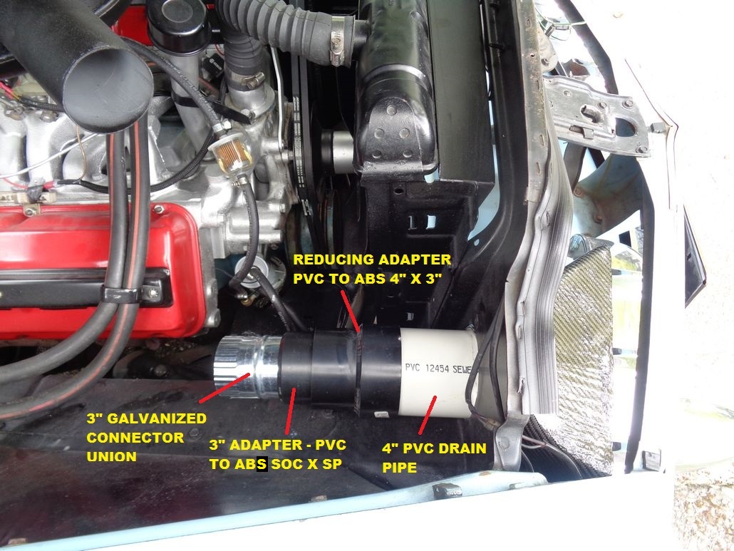 (AirScoopTo3inchHoseTransitionComponents.jpg) (AirScoopTo3inchHoseTransitionComponents.jpg)
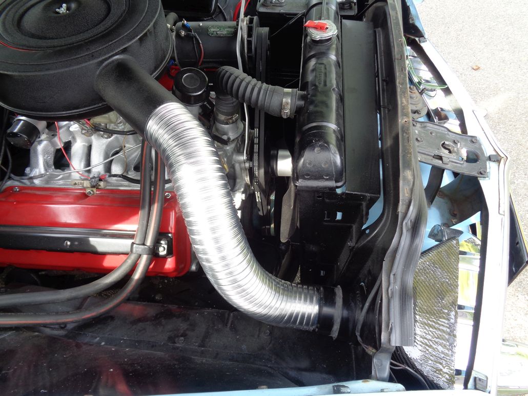 (AirScoopTo3inchHoseTransitionComponentsCutDown.jpg) (AirScoopTo3inchHoseTransitionComponentsCutDown.jpg)
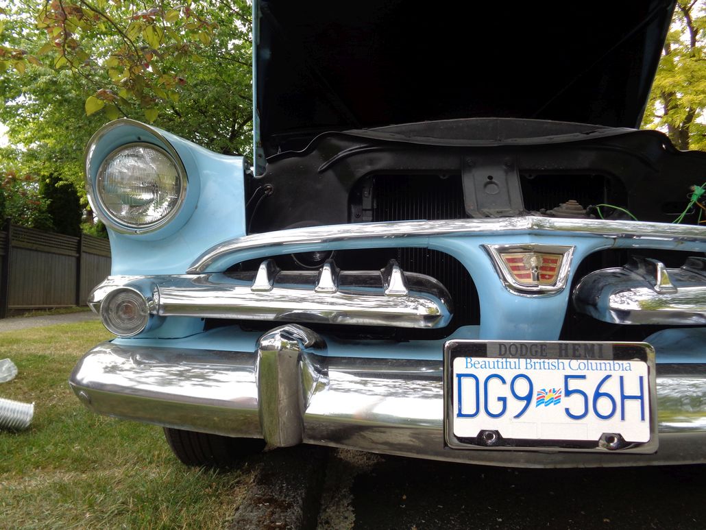 (AirScoopInPlaceShowingTheWhitePVCSpoolPiece_1.jpg) (AirScoopInPlaceShowingTheWhitePVCSpoolPiece_1.jpg)
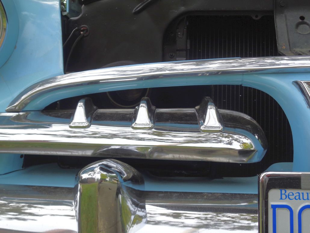 (AirScoopInPlaceShowingTheWhitePVCSpoolPiece_2.jpg) (AirScoopInPlaceShowingTheWhitePVCSpoolPiece_2.jpg)
Attachments
----------------
AirScoopTo3inchHoseTransitionComponents.jpg (245KB - 665 downloads)
AirScoopTo3inchHoseTransitionComponentsCutDown.jpg (162KB - 685 downloads)
AirScoopInPlaceShowingTheWhitePVCSpoolPiece_1.jpg (172KB - 649 downloads)
AirScoopInPlaceShowingTheWhitePVCSpoolPiece_2.jpg (120KB - 639 downloads)
|
|
| |
|
Expert 5K+
Posts: 9900
Location: Lower Mainland BC | Ran the converted OE air cleaner(with stacked filters) all winter and it was fine. On Friday, I sanded and recoated the carbon fibre "Ram Air" air scoop. Yesterday, after going for a nice run in the Dodge, I removed the converted air cleaner and re-installed the "Ram Air" air filter system. I was surprised: 1) the ram air was quieter (??) - the opposite of what I thought before, and 2) the engine didn't seem to run as well (??). I might have to install a flow limiting baffle in the ram air system after all.
From this:
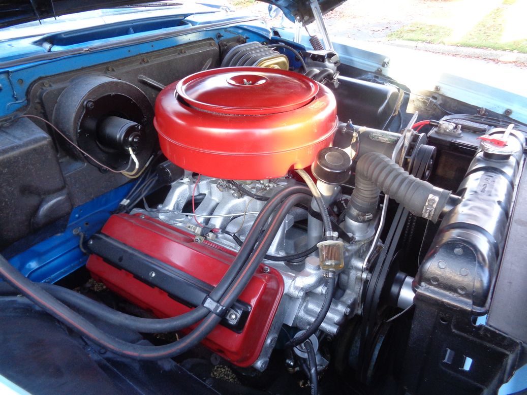
Back to this (old photo) (except with a much smoother/shinier scoop):

Edited by 56D500boy 2019-07-21 1:38 PM
|
|
| |
|
Expert 5K+
Posts: 5006
| you are probably running lean, that carb isn't able to handle all the air your throwing at it, you can richen it up and it should help, your going to eat more gas but you should then start to see performance gains.
Don't run lean man... You'll destroy it. Your bringing in alot of air i would expect. Pull the pipe how does the car run? with just the air cleaner open to the engine bay?
https://www.enginelabs.com/engine-tech/engine/high-speed-engine-tuni...
|
|
| |
|
Expert 5K+
Posts: 7400
Location: northern germany | mikes2nd - 2019-07-21 2:26 PM
you are probably running lean, that carb isn't able to handle all the air your throwing at it, you can richen it up and it should help, your going to eat more gas
Physically not possible. Cooler air makes an engine run more efficient, that is the performance gain, it is free, after you adjusted the idle/jetting for the cooler air (leaner mixture). At idle (?), if really a lean condition is the cause (?), once you adjusted the mixture it will idle faster/smoother and you can back off the curb idle screw. Same for jetting, you need less throttle opening for the same amount of power.
I installed several cold/ram air systems, all engines responded with a smoother idle in hot weather and yes, the mixture needs to be adjusted, especially for driving in cold weather. |
|
| |
|
Expert 5K+
Posts: 5006
| well it would only happen at higher speeds,of course cooler is better but its absolutely possible. even the article says so and it makes sense...
your saying he is running richer? he didn't say if it was an idle issue or when he is at high speed or accelerating. well need to know if its all the time or when its happening.
|
|
| |
|
Expert 5K+
Posts: 7400
Location: northern germany | mikes2nd - 2019-07-21 9:04 PM
well it would only happen at higher speeds,of course cooler is better but its absolutely possible. even the article says so and it makes sense...
your saying he is running richer? he didn't say if it was an idle issue or when he is at high speed or accelerating. well need to know if its all the time or when its happening.
What would happen only at higher speeds? With cooler, denser air an engine is always running more efficient. Where did you read I was saying he is running richer? No, colder air will of course lean out the mixture.
Yes, he didn't say if it is the idle or main circuit, that is why I added the question mark, but a lean condition can of course happen at any engine speed. I was just stating physical facts.
Edited by 1960fury 2019-07-22 3:46 PM
|
|
| |
|
Location: North Australia | Dave, any update on this? Steve. |
|
| |
|
Expert 5K+
Posts: 9900
Location: Lower Mainland BC | 60 Imp - 2020-02-05 12:08 AM
Dave, any update on this? Steve.
Not really. I am running the OE look D500 red "oil bath" (with the paper filter conversion) again for the winter. I did ad a "315 Hemi Head" sticker that I made for the chrome air cleaner to the black "Ram Air" air cleaner at some point but that is about all. I am still thinking about a cable-controlled baffle in the intake pipe/hose (or the snorkle) to limit the "Ram Air" air to some extent.
|
|
| |
|
Expert 5K+
Posts: 7400
Location: northern germany | 56D500boy - 2020-02-05 11:14 AM
I am still thinking about a cable-controlled baffle in the intake pipe/hose (or the snorkle) to limit the "Ram Air" air to some extent.
:)
Why? You ain't gonna have a big ram-effect anyway. |
|
| |
|
Expert 5K+
Posts: 9900
Location: Lower Mainland BC | .
I forgot that sometime ago I had found photos to the 53 Dodge "air scoop". I don't think that I had posted them up. (Until now)
So here they are, starting with the original brochure/advert showing the "Jet Air-flow hood" scoop. As shown in the photos, the scoop doesn't actually deliver cold air "directly to the carburetor". More like "to the vicinity of the air cleaner that sits on the carburetor"
Edited by 56D500boy 2020-03-24 12:50 PM
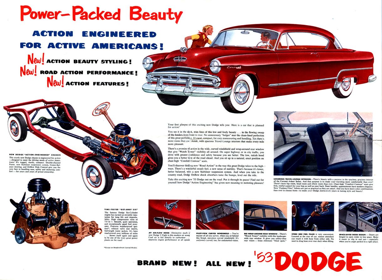 (AdvertShowingHoodScoop_small.jpg) (AdvertShowingHoodScoop_small.jpg)
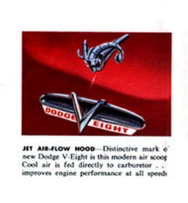 (AdvertShowingHoodScoop_Detail.jpg) (AdvertShowingHoodScoop_Detail.jpg)
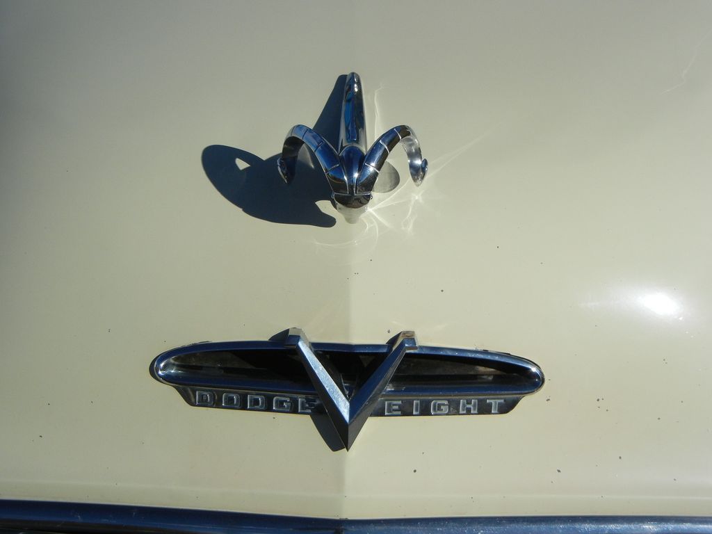 (53DodgeHoodScoopFromOutside_small.jpg) (53DodgeHoodScoopFromOutside_small.jpg)
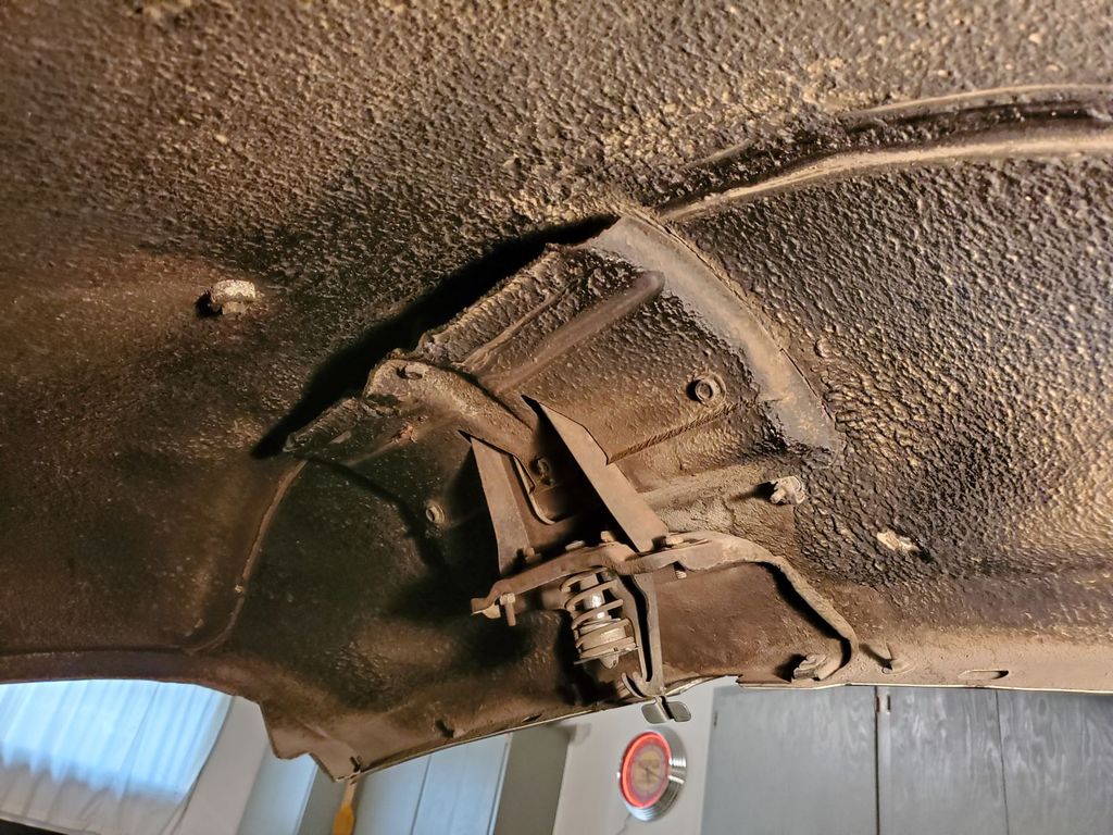 (53DodgeDuctingFromHoodScoopOverRadSupportToEngineBay_1_small.jpg) (53DodgeDuctingFromHoodScoopOverRadSupportToEngineBay_1_small.jpg)
Attachments
----------------
AdvertShowingHoodScoop_small.jpg (243KB - 520 downloads)
AdvertShowingHoodScoop_Detail.jpg (44KB - 540 downloads)
53DodgeHoodScoopFromOutside_small.jpg (59KB - 530 downloads)
53DodgeDuctingFromHoodScoopOverRadSupportToEngineBay_1_small.jpg (183KB - 503 downloads)
|
|
| |
|

Extreme Veteran
Posts: 406
Location: Hilltown, PA | "Ran the converted OE air cleaner(with stacked filters) all winter and it was fine. On Friday, I sanded and recoated the carbon fibre "Ram Air" air scoop. Yesterday, after going for a nice run in the Dodge, I removed the converted air cleaner and re-installed the "Ram Air" air filter system. I was surprised: 1) the ram air was quieter (??) - the opposite of what I thought before, and 2) the engine didn't seem to run as well (??). I might have to install a flow limiting baffle in the ram air system after all. :("
First, I'm not at all surprised that your perception is a quieter intake with the ram air set-up. Your factory (red) filter has an exposed element and is essentially an open element filter like most aftermarket units. Yes the housing provides some muffling of the intake noise, but not much. In addition that noise is generated close to you - under the hood, next to the firewall, near the HVAC system inlets and housing, etcetera.
The ram air system, on the other hand, is a fully enclosed air filter housing, with a sealed duct leading to an area about as far away from you (the driver) as possible. I'm sure the intake noise at the front of the car is significant - but being ahead of the radiator support, facing away from you, and low to the ground, you won't ever hear it.
Just for fun you should put a camera on the ground and do a couple of wide open throttle drive-by's with both air cleaner set-ups installed . . .
Now, as to your perception of the engine not running as well . . .
I can see a couple of possible explanations right off the bat, and have a couple of ideas that may require some thought.
First, lets address the things that would be fairly obvious. Chief among those is the air cleaner assembly itself. Based on what I can see, and my recollection of what you put together, the air filter housing you are using with the ram air has a completely different profile at the base of the carburetor. Many people don't understand this, but the shape of the air cleaner base is extremely important to effective fuel metering because it directly affects the airflow into the carb throat - the area where the air bleeds and emulsion tubes take their reference from. Anything that changes the airflow at this critical point in the carburetor will have a significant, and often detrimental effect on fuel metering. There have been plenty of articles written over the years demonstrating this and backing it up with dyno and flow bench testing.
Second, again related to your change in air cleaner housing, is the change in inlet air temperature. Where I live carb icing isn't much of an issue in July, but up your way I would guess it may be possible. Cooler outside air will also be more humid, and as that air passes through the venturi of the carb it accelerates and the pressure drops - also causing a drop in temperature. That drop in temperature along with the pressure drop causes humidity to condense, which then tries to evaporate, further cooling the metal of the carb body. This constant ongoing process can and will reduce the temperature of the carb throat to the point that condensing humidity begins to freeze - obstructing the aforementioned air bleeds and emulsion tubes, again to the detriment of fuel metering. While you might think this is unlikely, it is possible depending on the specifics of weather and your altered system. Because this symptom can vanish once the airflow is reduced it can be very difficult to detect by stopping the car and raising the hood.
And my final thought has to do with the overall effect of a sealed intake tract on a carbureted vehicle. Modern cars with port type fuel injection rely almost exclusively on this type of intake system, and can do so because fuel metering is almost completely independent from the physics of inlet airflow. Air intake is measured, along with other important factors such as load, throttle position, etcetera, and fuel injection quantity and timing is determined based on a programmed map, and then executed. On a carbureted engine, however, intake dynamics have a substantial effect of fuel metering (as described above). In the 60's this type of sealed cold air intake was a popular upgrade, and many were manufactured and sold with advertising like what you have referenced. However as you have experienced, the results were not always as expected, or claimed in the advertising. While the theory is sound - cooler air is denser air, denser air makes more power, ram air or air under pressure is denser and makes more power - the actual practical application is far more complex. Turbulence, inconsistent pressures and temperatures, varying humidity - all of these created an almost impossible tuning situation for anyone using true ram air intakes. Yes, racers did find it to be an effective tool, but in most cases those engines are tuned to run well within a very narrow powerband, greatly simplifying the necessary trial and error tuning of the intake and fuel metering.
For practical road use simply look the vehicle manufacturers. Hood scoops, ram air, fresh air - there were as many names as there were designs. But they all have key elements in common. All of these systems had some method of draining unwanted water from the intake system - usually baffles and drain holes within the fresh air plenums. These are still used today. Most also had some sort of manual cable or vacuum operated baffle to allow for underhood air to enter the system during engine warm up, primarily to prevent carb icing. (This is less of an issue today, but still occurs in some applications - hence the use of heated throttle bodies). Most importantly, however, is that every one of these factory "ram air" systems had a method to bleed off excessive pressure in the air intake system. How excessive? Lets just say any. For example the famed Chrysler hood mounted air boxes on the B-body cars were equipped with slots on the side covered with rubber flaps - flaps which would open at the slightest pressure above ambient. Ford, GM, and AMC systems all had similar ways to prevent pressure from actually building up in their "forced air" inlet systems. Why? Because with carburetor(s) the task of tuning to all possible variations of throttle position, load, inlet pressure, and temperature would be impossible. The mechanical carburetor simply cannot perform that degree of metering. Hell - a carb can't even compensate for altitude - how do you expect it to adjust for a road speed related change in intake pressure?
So the truth is that the manufacturers bowed to the popularity of "ram air" but never actually incorporated it. Instead they built functional and useable (and fun) cold air intake systems.
I suspect that if you hybridized your air filter housing to incorporate a properly shaped based, especially around the carb throats, installed a baffle at the end of the intake tube inside the air filter housing to distribute the airflow around the filer rather than directly into it, incorporated a movable baffle that not only closed the cold air inlet, but opened the intake to the area inside the engine compartment (preferably over one of the exhaust manifolds), and most importantly opened holes in the back or base of the air filer housing that would allow air coming into the housing to pass through, your performance issues would largely be eliminated. A little richening of the idle mixture, and possibly a minor change in jetting, would take advantage of the now available cooler air.
By no accident the set-up you would end up with would be very similar to that used on most cars in the mid to late 80's, right at the end of the carburetor era.
Gregg
|
|
| |
|
Expert 5K+
Posts: 7400
Location: northern germany | LostDeere59 - 2020-03-26 2:24 PM
Ford, GM, and AMC systems all had similar ways to prevent pressure from actually building up in their "forced air" inlet systems. Why? Because with carburetor(s) the task of tuning to all possible variations of throttle position, load, inlet pressure, and temperature would be impossible. The mechanical carburetor simply cannot perform that degree of metering. Hell - a carb can't even compensate for altitude - how do you expect it to adjust for a road speed related change in intake pressure?
Gregg
Well, it works for carbureted motorcycles for decades with a big, measurable power gain and it works for me for almost 30 years,
except when its really cold, I disconnect the tubes.
I couldn't wish for a better running car, and after about 170k miles with it, the engine still runs perfect at @330K miles with
a top speed of above 140 mph (conservative statement to avoid the usual comments), no malfunction or problems whatsoever,
except for a blown out a.c. housing seal (before I glued it to the hsg) at high speed, that made me feel the power loss without ram air.
Furthermore, blow thru (not draw thru) turbos/superchargers with carbs, that work at a MUCH higher pressure than a ram air
(don't know what they do with the power valves, there are special blow-thru carbs, but this is not a problem with r.a.), have been successfully used for over half a century.
https://www.youtube.com/watch?v=UCTEdodRpWI |
|
| |
|
Expert 5K+
Posts: 5006
| uh oh Sidds gonna call you a liberal Gregg...
I certainly like the experiment. I was joking when i said he would blow his engine, but i wasn't when i said it will change things, depending on speed it could run leaner.. i put the link to the extreme... Gregg your a more patient man than I...
|
|
| |
|
Expert 5K+
Posts: 9664
Location: So. Cal | I'll throw my theory to the wind here. You've added quite a bit of turbulence to your intake stream. It takes pressure to overcome the negative effects of that turbulence. That means that there is a minimum speed at which you break even with this setup. To get any gain, you have to go faster than that. I suspect that you don't really see that benefit driving stop light to stop light, and it wouldn't surprise me that you would see a decline in performance in that range. To get the benefit from this you would need to run near freeway speeds. |
|
| |
|
Expert 5K+
Posts: 9900
Location: Lower Mainland BC | .
Okay. I will accept that it is possible that the air-fuel ration could be wrong (lean) if I drive the car "fast" (how fast? I don't know (I've only had it to 75 mph (one time) (on a "closed circuit, private track") (Nyuk, Nyuk))). O realize that it is not a modern fuel injection system with an air-flow meter and an O2 sensor feed back loop and a computer with a "map" inside to adjust fueling to meet the air flow and O2 sensor inputs.
I won't buy a turbulence issue. The run from the scoop to the air cleaner snorkle is all smooth long radius bends. The original air distribution baffle is still in the air cleaner so the air gets distributed around the circumference of the filter and the WIX filter element will straighten out the flow if there is any turbulence. Down into the carb is stock big block air cleaner (with about a 1" high spacer).


Edited by 56D500boy 2020-03-27 7:53 PM
|
|
| |
|
Expert 5K+
Posts: 6500
Location: Newark, Texas (Fort Worth) | If you every want to change to black tubing; CEET16 is 4'' black aero-ducting that can handle the heat. http://aircraftproducts.wicksaircraft.com/viewitems/air-supplies/ae... Marc. |
|
| |
|
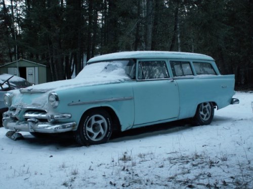
Extreme Veteran
Posts: 507
Location: Invermere B.C. Canada - Rocky Mountains | 56D500boy - 2020-02-05 9:14 AM I am still thinking about a cable-controlled baffle in the intake pipe/hose (or the snorkel) to limit the "Ram Air" air to some extent. :)
That was from a older post.
I was going to mention, but not sure if it mattered at the time, that when taking the 318 fuel injected engine out of a Dakota that is now in my '56, the Dakota originally (because of the fuel injection) had a OEM cold air duct from the front rad support to the air cleaner.
The critical item (to me) was that the air intake opening had an angled baffle from the factor install 1/3 across the intake opening. Probably not relevant information for carb equipped cars but as I am going to use a twin cold air aftermarket ducts on my '56 that ... if Dodge used a baffle on the Dakota ... than so should I on my '56.
(Ignore as necessary) |
|
| |
|
Expert
Posts: 3967
Location: DFW, TX | The paper air filter surrounding the carb inlet is going to disrupt most of the "ram effect" (inertia of the incoming column of air) that the inlet tube could, in theory, deliver. If sealed properly, it will deliver ambient air and that can lead to a possible performance improvement if the a/f ratio is tuned to match.
And that is a key reason OEMs only routed ambient air to carburetors on the high-perf models; ambient air can easily have a 100-degree swing in certain areas. That guarantees the car will perform poorly when the air density is higher or lower than what the car was tuned for. So these engines were tuned to ingest hot engine compartment air. It is less optimal for maximum horsepower but the car will run much more consistently.
Just my .02, I don't want to fight anyone over it. |
|
| |
|
Expert 5K+
Posts: 9900
Location: Lower Mainland BC |
Thanks for the heads up on the black ducting. I know that is is/was used by other factory systems, like this Olds 442 and somebody's 68 Fury III with a 360:
Edited by 56D500boy 2020-04-01 4:15 PM
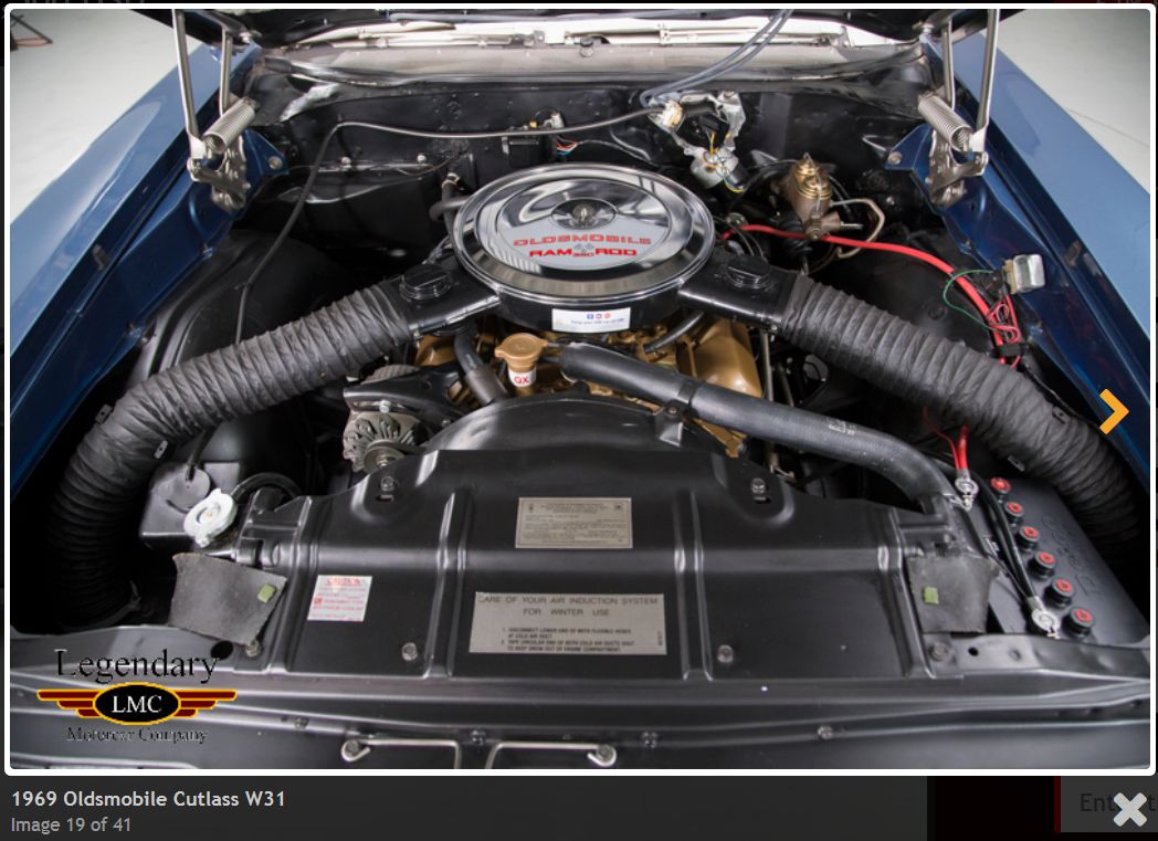 (69OldsCutlassW31_1.jpg) (69OldsCutlassW31_1.jpg)
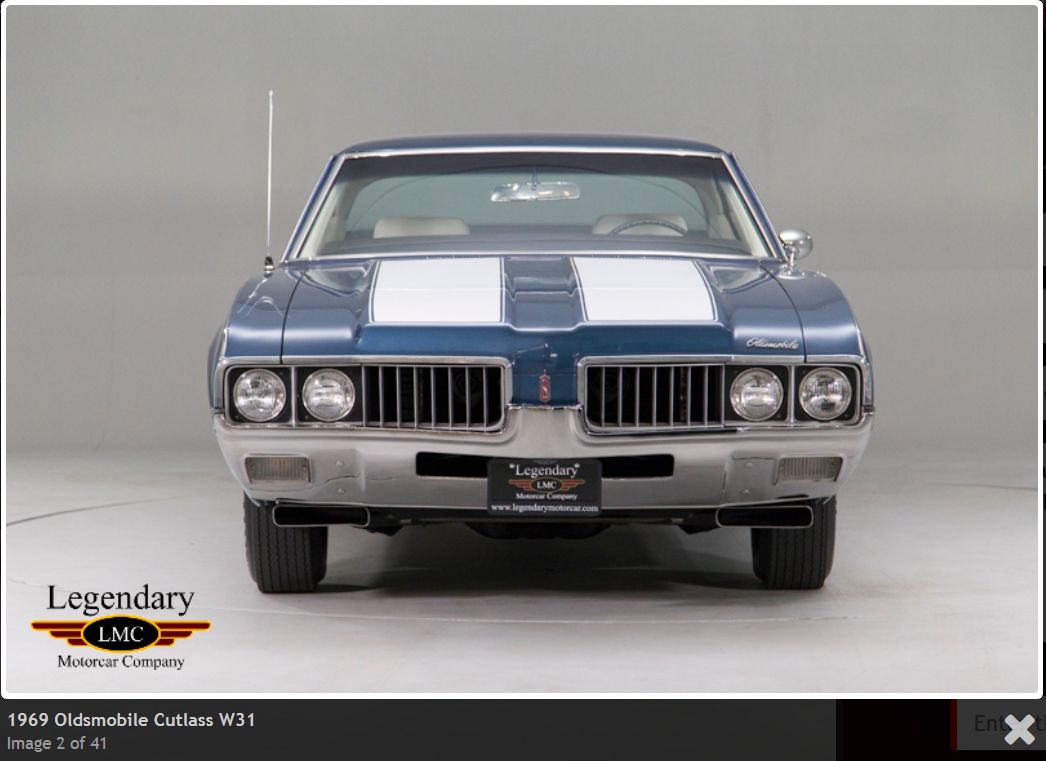 (69OldsCutlassW31_2.jpg) (69OldsCutlassW31_2.jpg)
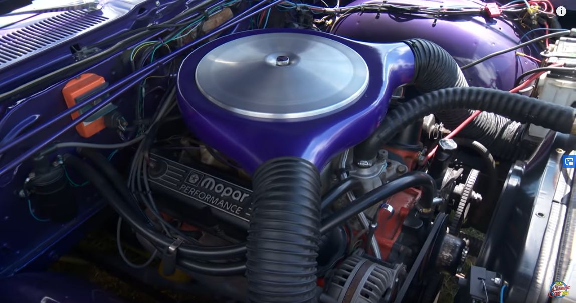 (360RamAirIn68Fury3Hardtop_1.jpg) (360RamAirIn68Fury3Hardtop_1.jpg)
Attachments
----------------
69OldsCutlassW31_1.jpg (123KB - 491 downloads)
69OldsCutlassW31_2.jpg (71KB - 500 downloads)
360RamAirIn68Fury3Hardtop_1.jpg (105KB - 508 downloads)
|
|
| |
|
Expert 5K+
Posts: 9900
Location: Lower Mainland BC | .
Turns out that 1952 Desoto with the new 276.1 cu in Firedome V8 also had some kind of "Air-Vent" hood "scoop":
Edited by 56D500boy 2020-04-02 4:40 PM
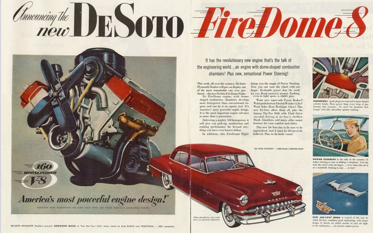 (1952DesotoFiredomeAdvertShowingAirVentHood.jpg) (1952DesotoFiredomeAdvertShowingAirVentHood.jpg)
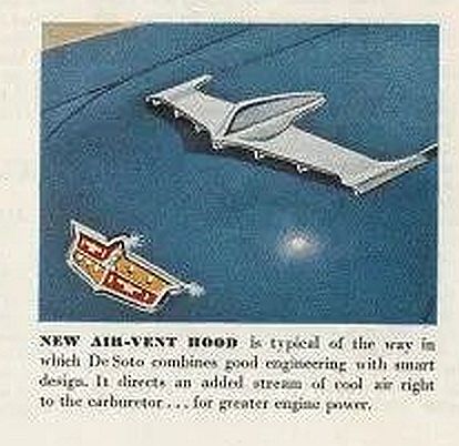 (1952DesotoFiredomeAdvertShowingAirVentHood_Detail.jpg) (1952DesotoFiredomeAdvertShowingAirVentHood_Detail.jpg)
Attachments
----------------
1952DesotoFiredomeAdvertShowingAirVentHood.jpg (202KB - 480 downloads)
1952DesotoFiredomeAdvertShowingAirVentHood_Detail.jpg (35KB - 482 downloads)
|
|
| |
|
Expert 5K+
Posts: 9900
Location: Lower Mainland BC | .
I hesitate to post this (please don't turn this into another sh*tsstorm) *BUT* to finalize how Dodge imagined the air was getting from the functional (??) hood scoop (fresh air inlet) to the engine bay, there was apparently,
a) a dip in the rad support and
b) somebody with a factory hammer the banged down the top of the top rad tank to let the air pass towards the air cleaner.
This was shown in a 1954 Coronet Suburban (hemi with overdrive - nice) as shown below:
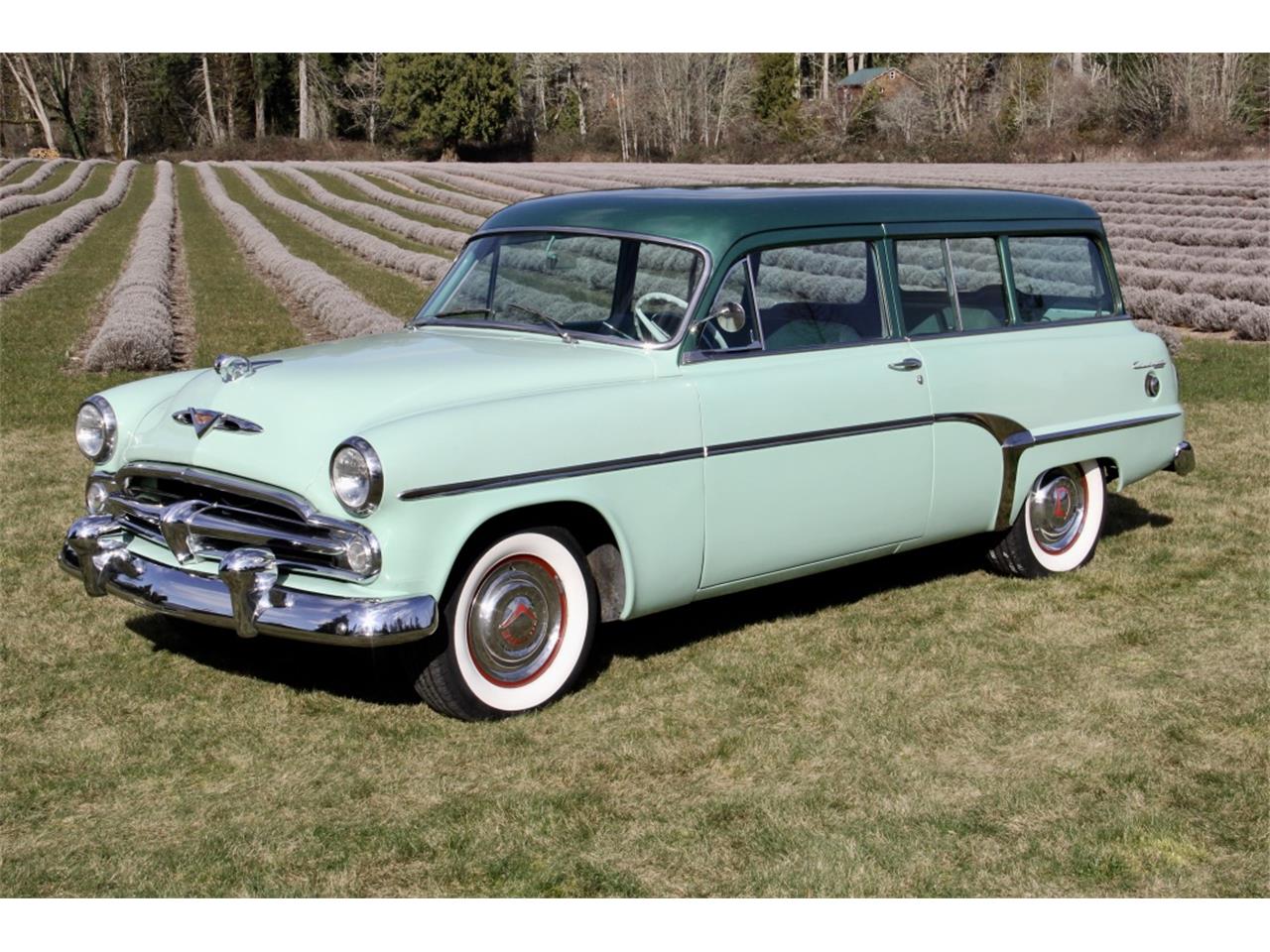 (20046727-1954-dodge-suburban-std_ShowingHoodScoopForFreshAir.jpg) (20046727-1954-dodge-suburban-std_ShowingHoodScoopForFreshAir.jpg)
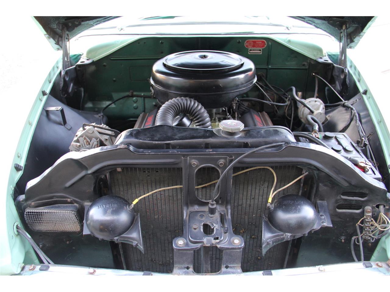 (20046727-1954-dodge-suburban-std_RadSupportShowingDipToLetFreshAirIntoEngineBay.jpg) (20046727-1954-dodge-suburban-std_RadSupportShowingDipToLetFreshAirIntoEngineBay.jpg)
Attachments
----------------
20046727-1954-dodge-suburban-std_ShowingHoodScoopForFreshAir.jpg (203KB - 481 downloads)
20046727-1954-dodge-suburban-std_RadSupportShowingDipToLetFreshAirIntoEngineBay.jpg (144KB - 468 downloads)
|
|
| |
|
Expert 5K+
Posts: 9900
Location: Lower Mainland BC | .
Found this today. Huh...
Edited by 56D500boy 2021-03-24 2:41 AM
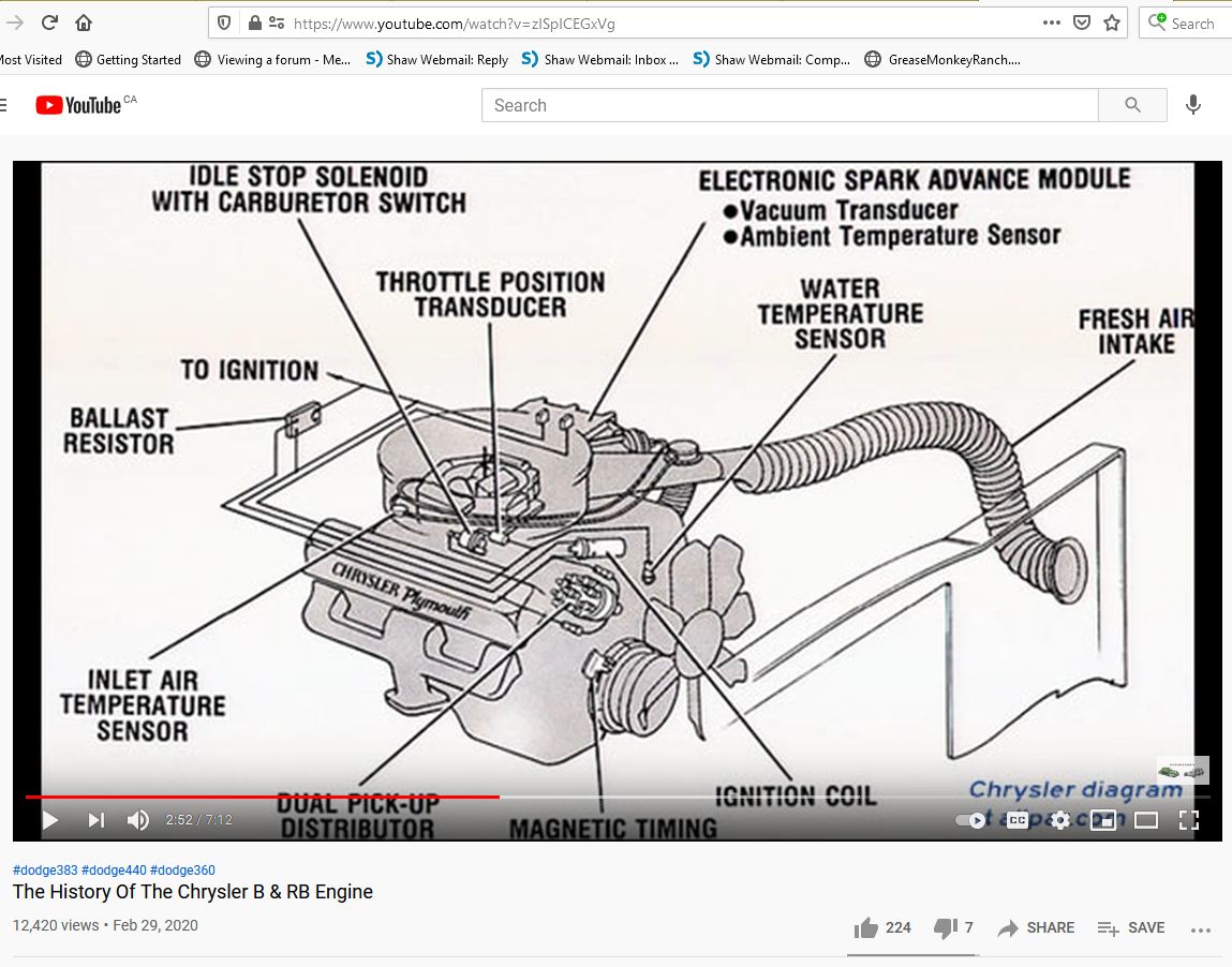 (ChryslerRamAir.jpg) (ChryslerRamAir.jpg)
Attachments
----------------
ChryslerRamAir.jpg (144KB - 374 downloads)
|
|
| |
|
Expert 5K+
Posts: 9900
Location: Lower Mainland BC | .
I wonder whether this (on somebody's 68 Fury III with a 360):

is this Spectrum SPE-733 (or - 732) from Summit Racing:
Edited by 56D500boy 2024-02-08 2:04 PM
 (SPE-733FromSummitRacing.jpg) (SPE-733FromSummitRacing.jpg)
Attachments
----------------
SPE-733FromSummitRacing.jpg (102KB - 23 downloads)
|
|
| |
|
Expert 5K+
Posts: 7400
Location: northern germany | Powerflite - 2020-03-27 11:59 AM
I'll throw my theory to the wind here. You've added quite a bit of turbulence to your intake stream. It takes pressure to overcome the negative effects of that turbulence. That means that there is a minimum speed at which you break even with this setup. To get any gain, you have to go faster than that. I suspect that you don't really see that benefit driving stop light to stop light, and it wouldn't surprise me that you would see a decline in performance in that range. To get the benefit from this you would need to run near freeway speeds.
I know its 4 yo post. The air filter won't let any turbolences pass thru. even if there are turbolences, it will never restrict the openig in the air cleaner hsg, if that was meant. Cooler, denser air makes more power, so you have a power gain from idle to top speed. That is why every new car has a cold air inlet. Ford USA started using it in the 50s. It will make an engine run more efficient and cleaner. Check my "valve" thread to see, how clean my pistons and valves looked after 63 years and 350 000 miles of almost daily use. |
|
| |