|
|
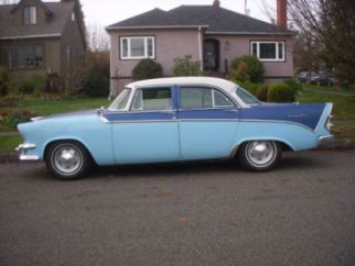
Expert 5K+
Posts: 9904
       
Location: Lower Mainland BC | For a 55 or 56 Plymouth and/or Dodge and maybe Desoto?
I was out furthering my investigations of a PF to TF conversion and knowing that I would have to move the mount to the rear by about 4", I was trying to figure out how the rear engine/transmission mount cross-member mounted to the frame.
From what I have figured out, there are "ears" welded to the frame (one on each side) to which the cross-member is bolted. I looked through my chassis photos (from other people) and I can sort of see what is going on but I am hoping that somebody could post a detailed photo of the "ears" with the cross-member removed.
This is what I have so far:
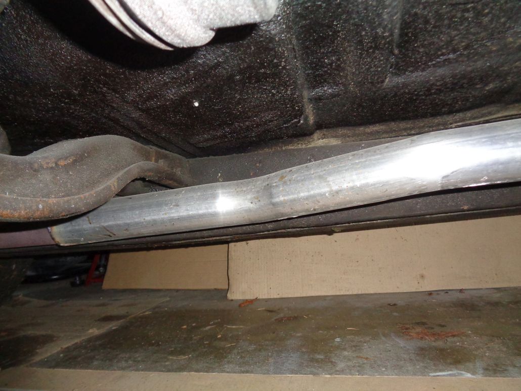 (56DodgePowerFliteRearTransMount_PassengerSideFromRear.jpg) (56DodgePowerFliteRearTransMount_PassengerSideFromRear.jpg)
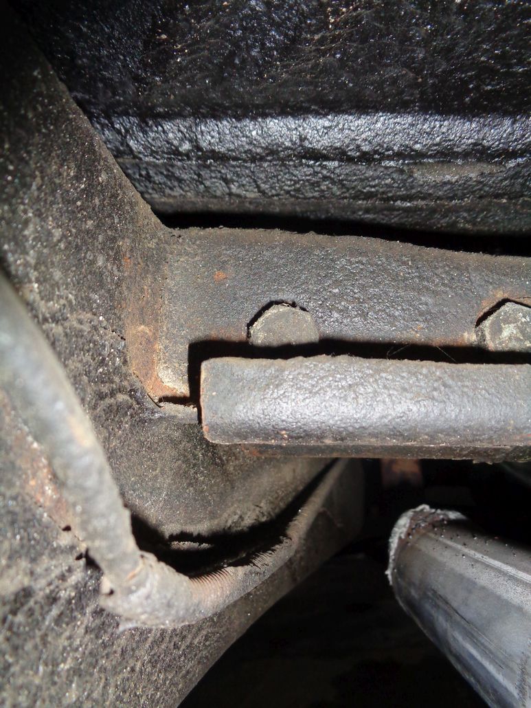 (56DodgePowerFliteRearTransMount_DriversSideFromRear.jpg) (56DodgePowerFliteRearTransMount_DriversSideFromRear.jpg)
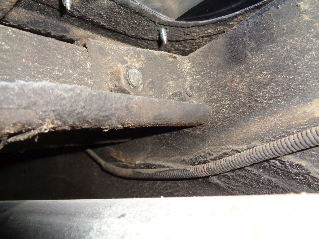 (56DodgePowerFliteRearTransMount_DriversSideFromFront.jpg) (56DodgePowerFliteRearTransMount_DriversSideFromFront.jpg)
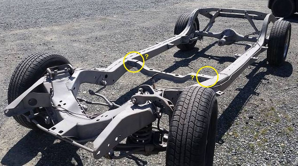 (1955PlymouthChassis_4.jpg) (1955PlymouthChassis_4.jpg)
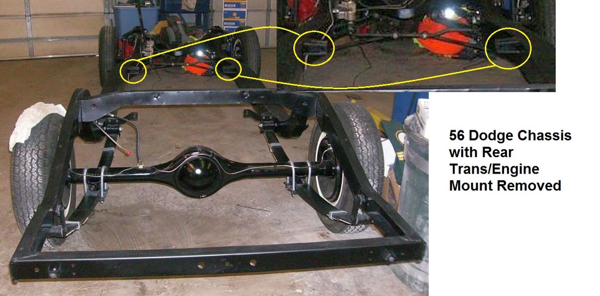 (56LaFemmeD500BodyOffChassis_WithRearEngineMountRemoved.jpg) (56LaFemmeD500BodyOffChassis_WithRearEngineMountRemoved.jpg)
Attachments
----------------
 56DodgePowerFliteRearTransMount_PassengerSideFromRear.jpg (137KB - 457 downloads) 56DodgePowerFliteRearTransMount_PassengerSideFromRear.jpg (137KB - 457 downloads)
 56DodgePowerFliteRearTransMount_DriversSideFromRear.jpg (189KB - 427 downloads) 56DodgePowerFliteRearTransMount_DriversSideFromRear.jpg (189KB - 427 downloads)
 56DodgePowerFliteRearTransMount_DriversSideFromFront.jpg (179KB - 441 downloads) 56DodgePowerFliteRearTransMount_DriversSideFromFront.jpg (179KB - 441 downloads)
 1955PlymouthChassis_4.jpg (245KB - 416 downloads) 1955PlymouthChassis_4.jpg (245KB - 416 downloads)
 56LaFemmeD500BodyOffChassis_WithRearEngineMountRemoved.jpg (164KB - 415 downloads) 56LaFemmeD500BodyOffChassis_WithRearEngineMountRemoved.jpg (164KB - 415 downloads)
|
|
| |
|

Expert 5K+
Posts: 9904
       
Location: Lower Mainland BC | Today, while trying to find info about 56 Plymouth Convertible body mounts for someone here, I bumped into a section in the 55-58 Mopar parts catalogue that I did not know was there. It has some diagrams that get me closer to knowing what I will need to move the trans mount back when I (eventually) install the longer Torqueflite transmission in my 56 Dodge.
BUT I am still hoping for real photos. 
This is what I found:
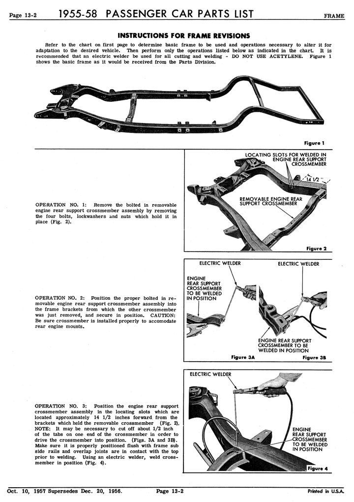 (TransmissionMountRevisions_1.jpg) (TransmissionMountRevisions_1.jpg)
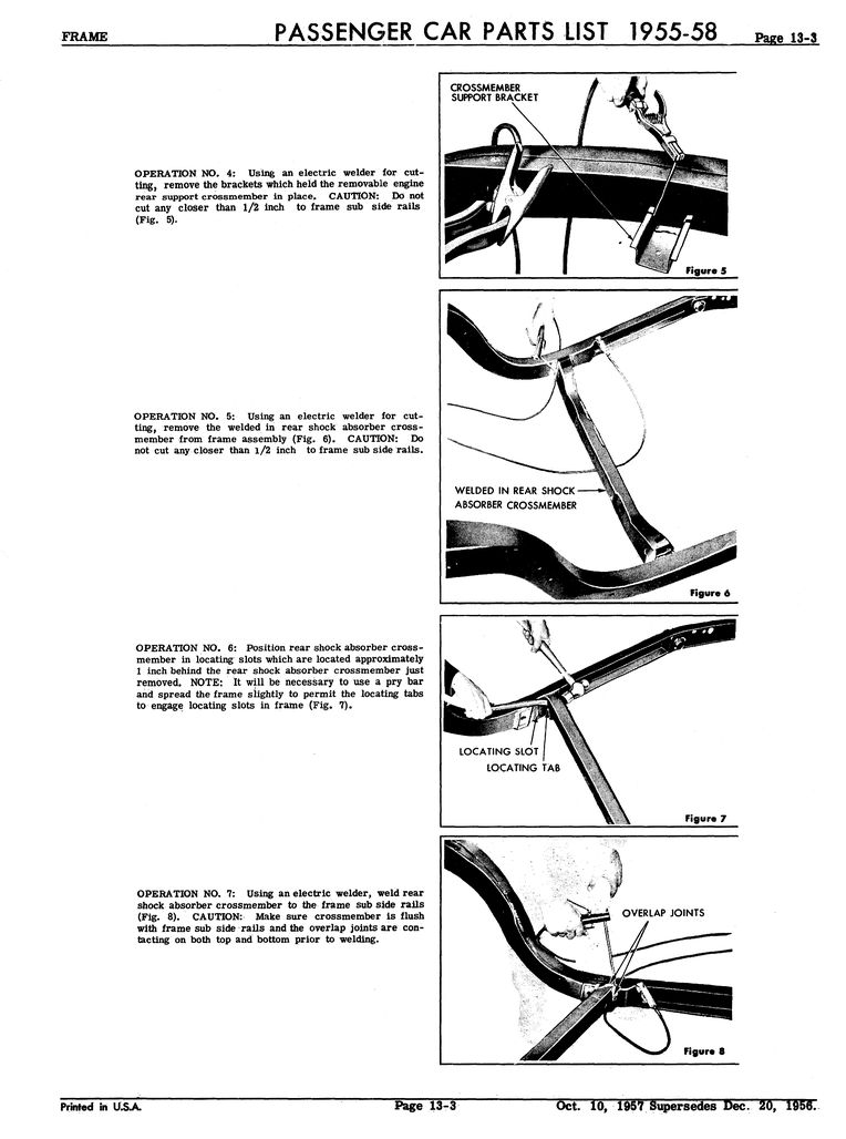 (TransmissionMountRevisions_2.jpg) (TransmissionMountRevisions_2.jpg)
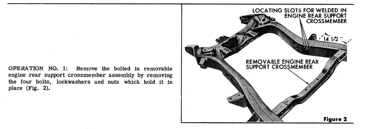 (TransmissionMountDetail_1.jpg) (TransmissionMountDetail_1.jpg)
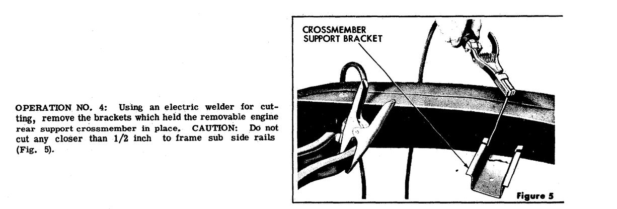 (TransmissionMountDetail_2.jpg) (TransmissionMountDetail_2.jpg)
Attachments
----------------
 TransmissionMountRevisions_1.jpg (131KB - 441 downloads) TransmissionMountRevisions_1.jpg (131KB - 441 downloads)
 TransmissionMountRevisions_2.jpg (102KB - 427 downloads) TransmissionMountRevisions_2.jpg (102KB - 427 downloads)
 TransmissionMountDetail_1.jpg (81KB - 437 downloads) TransmissionMountDetail_1.jpg (81KB - 437 downloads)
 TransmissionMountDetail_2.jpg (68KB - 411 downloads) TransmissionMountDetail_2.jpg (68KB - 411 downloads)
|
|
| |
|

Expert 5K+
Posts: 9904
       
Location: Lower Mainland BC | 56D500boy - 2019-01-13 8:47 PM
BUT I am still hoping for real photos. 
Ralf N. from Finland was nice enough to send me a couple of photos of his beautiful 56 Dodge Coronet chassis from when he was doing a body-off restoration back in 2010. I can at least see the support better. (Thanks Ralf) 
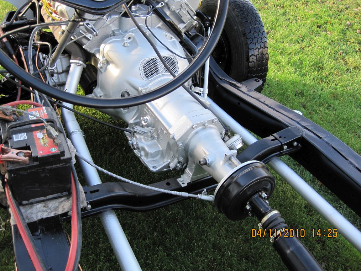 (RalfNFromFinlandsBeautiful56CoronetChassis_1.jpg) (RalfNFromFinlandsBeautiful56CoronetChassis_1.jpg)
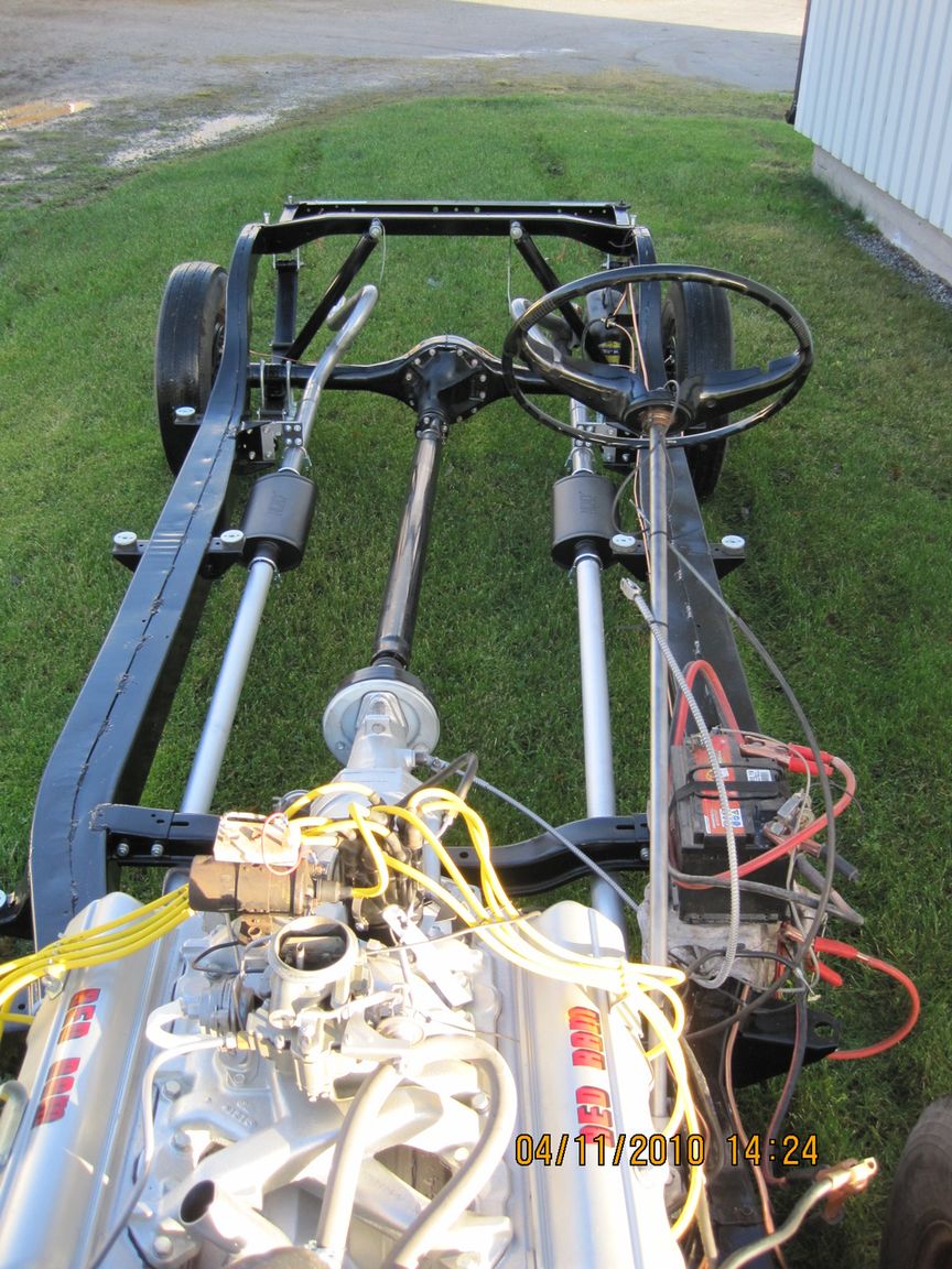 (RalfNFromFinlandsBeautiful56CoronetChassis_2.jpg) (RalfNFromFinlandsBeautiful56CoronetChassis_2.jpg)
Attachments
----------------
 RalfNFromFinlandsBeautiful56CoronetChassis_1.jpg (239KB - 415 downloads) RalfNFromFinlandsBeautiful56CoronetChassis_1.jpg (239KB - 415 downloads)
 RalfNFromFinlandsBeautiful56CoronetChassis_2.jpg (221KB - 428 downloads) RalfNFromFinlandsBeautiful56CoronetChassis_2.jpg (221KB - 428 downloads)
|
|
| |
|

Expert 5K+
Posts: 9904
       
Location: Lower Mainland BC | Never mind. Based on Ralf N's photo, I've figured it out how to make new mounting ears for the transmission cross member: out of three pieces, i.e. two side pieces and one top piece with the mirror-image sides welded to the top piece. Biggest issue would be bending the lip on the side pieces.
See attached. I could easily mock the "ear" up in cardboard to test the theory.

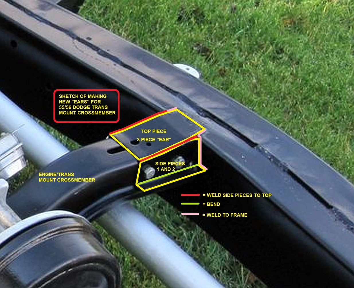 (MountEarsDetail_Annotated_small.jpg) (MountEarsDetail_Annotated_small.jpg)
Attachments
----------------
 MountEarsDetail_Annotated_small.jpg (173KB - 435 downloads) MountEarsDetail_Annotated_small.jpg (173KB - 435 downloads)
|
|
| |
|
Expert
Posts: 2289
     
Location: Eastern Iowa | Dave, I still have the frame section and the X member from the 57 you got the trans from. |
|
| |
|

Expert 5K+
Posts: 9904
       
Location: Lower Mainland BC | finsruskw - 2019-01-15 9:47 AM
Dave, I still have the frame section and the X member from the 57 you got the trans from.
Thanks Dave. The 57-58 cross-member/mounts are different than the 55-56 mounts because of the torsion bar mounting requirements:
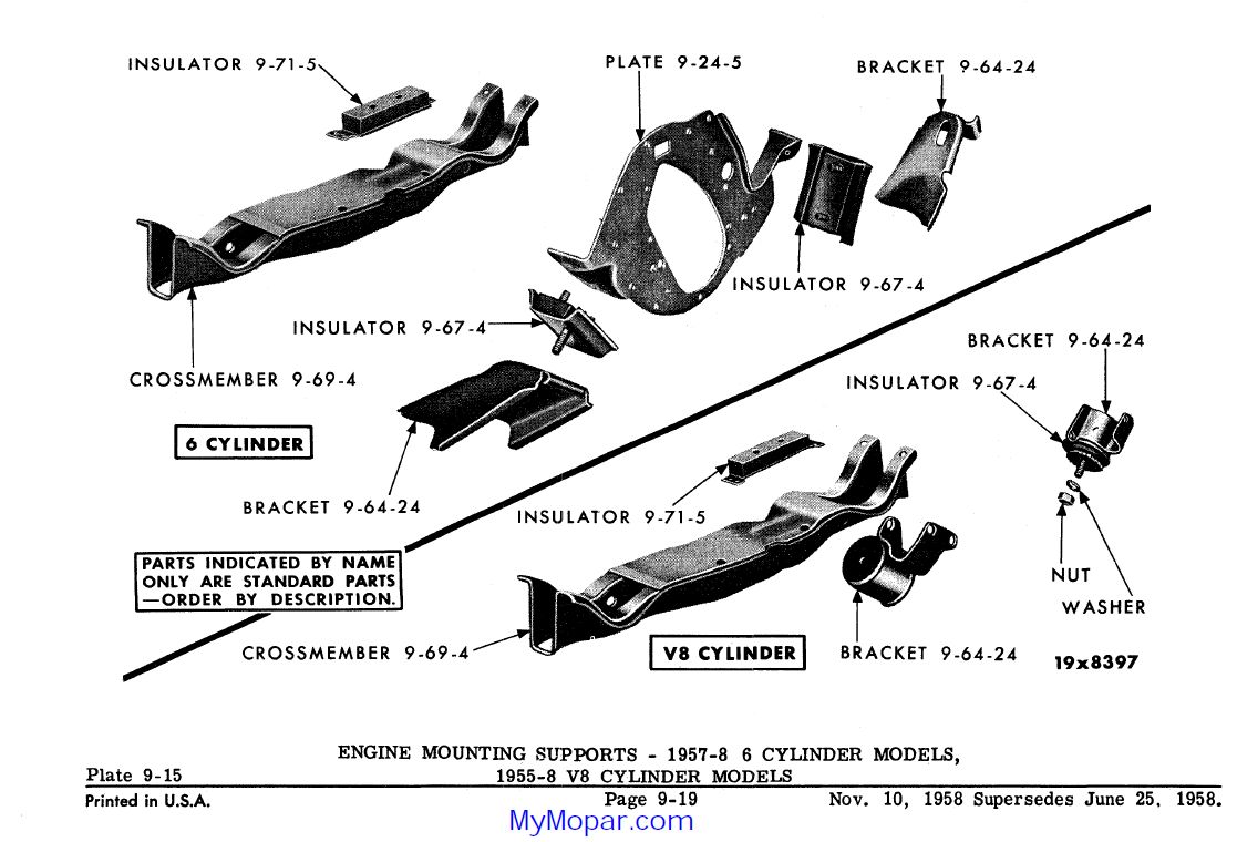 (57-58TransmissionMountDiagram.jpg) (57-58TransmissionMountDiagram.jpg)
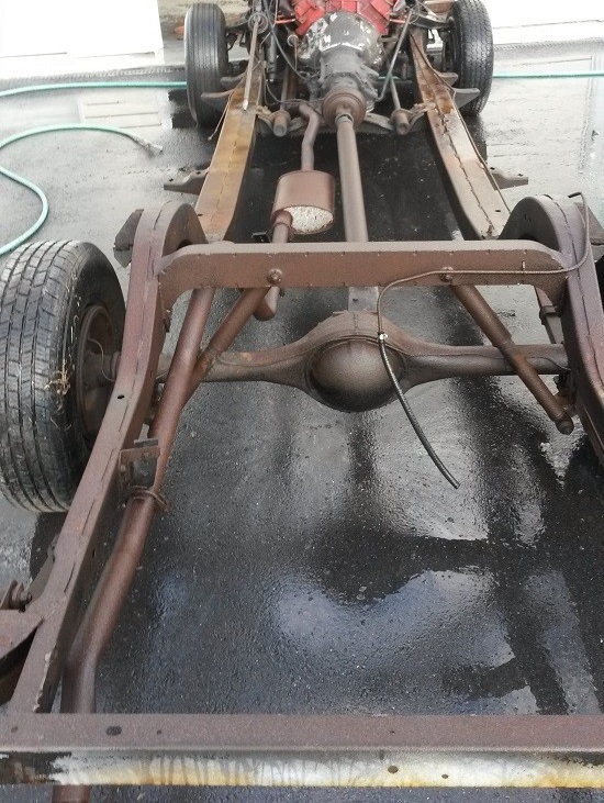 (frame58desoto.jpg) (frame58desoto.jpg)
Attachments
----------------
 57-58TransmissionMountDiagram.jpg (118KB - 438 downloads) 57-58TransmissionMountDiagram.jpg (118KB - 438 downloads)
 frame58desoto.jpg (211KB - 430 downloads) frame58desoto.jpg (211KB - 430 downloads)
|
|
| |
|

Expert 5K+
Posts: 9904
       
Location: Lower Mainland BC | 56D500boy - 2019-01-15 1:31 AM I could easily mock the "ear" up in cardboard to test the theory.

If only 1/4" steel bent like cardboard and I had a welder, not a hot glue gun. 
The next mock-up would be based on measurements, not just eyeballing. 
Edited by 56D500boy 2019-01-15 12:29 PM
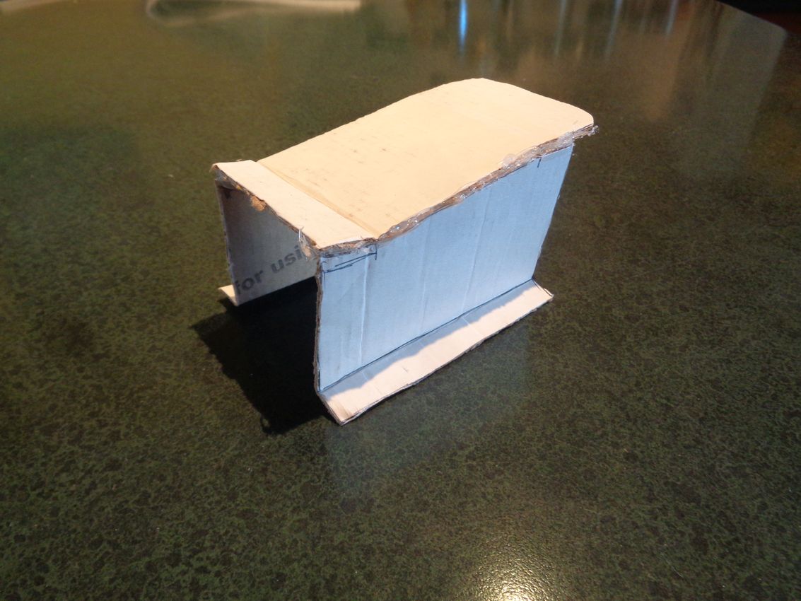 (56DodgeTransmissionCrossMemberMountingEarMockUp_1.jpg) (56DodgeTransmissionCrossMemberMountingEarMockUp_1.jpg)
 (56DodgeTransmissionCrossMemberMountingEarMockUp_2.jpg) (56DodgeTransmissionCrossMemberMountingEarMockUp_2.jpg)
Attachments
----------------
 56DodgeTransmissionCrossMemberMountingEarMockUp_1.jpg (138KB - 440 downloads) 56DodgeTransmissionCrossMemberMountingEarMockUp_1.jpg (138KB - 440 downloads)
 56DodgeTransmissionCrossMemberMountingEarMockUp_2.jpg (114KB - 425 downloads) 56DodgeTransmissionCrossMemberMountingEarMockUp_2.jpg (114KB - 425 downloads)
|
|
| |
|

Expert 5K+
Posts: 9904
       
Location: Lower Mainland BC | 56D500boy - 2019-01-15 9:26 AM
The next mock-up would be based on measurements, not just eyeballing. 
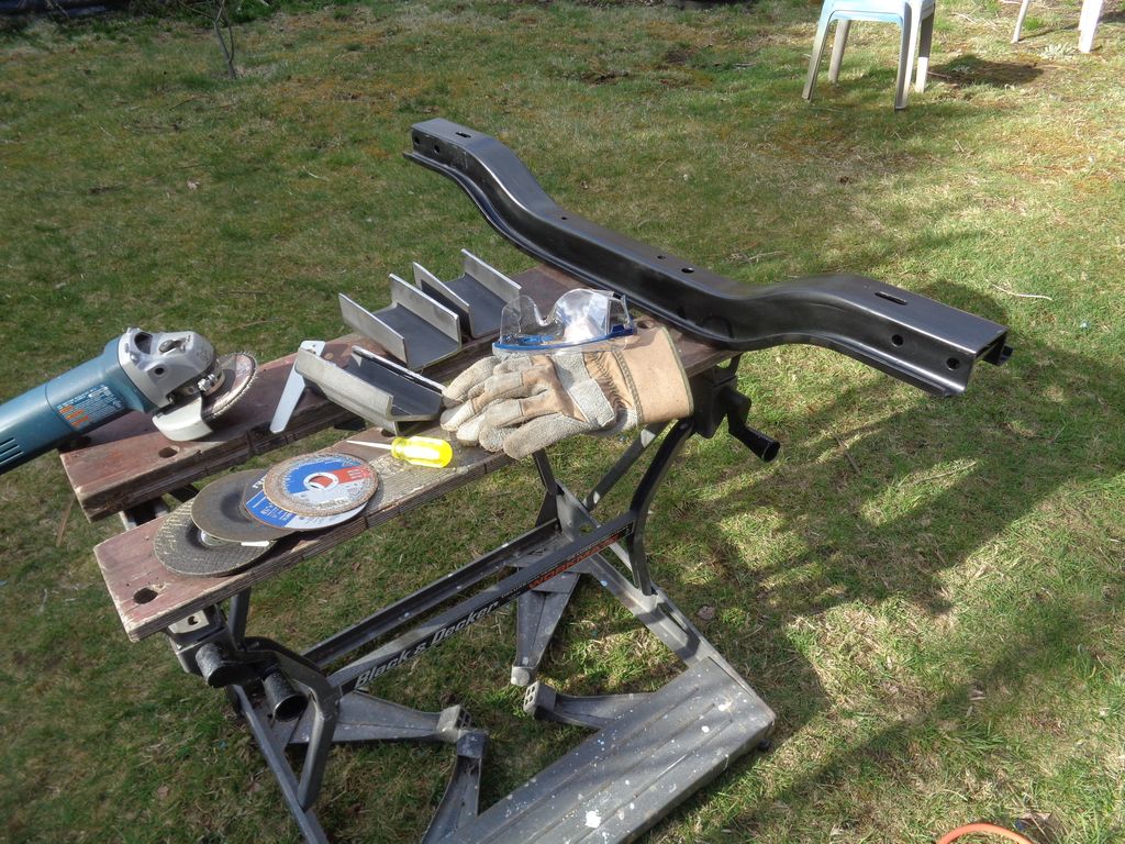
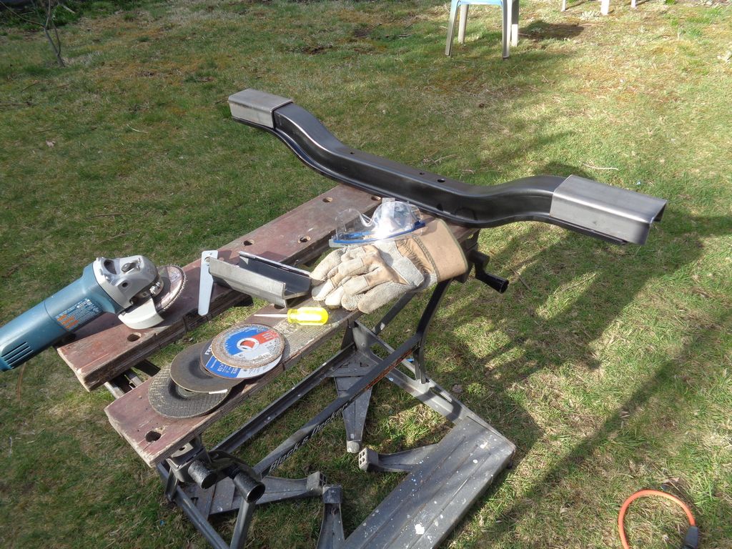
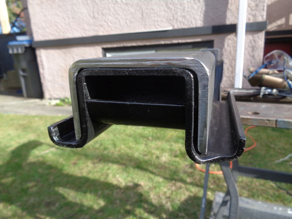
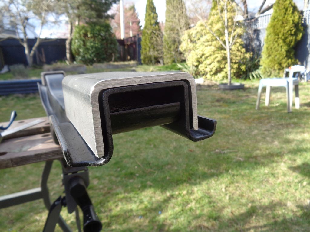
I decided that I could not reproduce the factory ears per se. Instead, I went to the "Metals Supermarket" (tm) (a real place) with the cross member and tried a few square tubes that looked like they could be cut to slip over the cross member (or in reality, that the cross member could slip UP into the tubing). I chose 3" x 3" x 3/16" tubing since the next size down was too small and 1/4" thick was too thick. I also purchased some 6" wide x 3/16" hot rolled bar stock to make the end plates for mounting the ears to the inside of the car frame.
Talking to my fabricator neighbour we decided that the end plates (with the new "ears" welded to the plate) could be fastened to the frame with nutserts and bolts and, if I felt the need, an inch or so of welding "stitching" added to each edge of the end plates (on both sides of the car) (to be determined).
Here are the new ears that I cut from the 3" x 3" tubing today. I have to decide whether to leave them 6" long or cut them down to something like 5".
There is likely to be a spacer washer tacked to the inside of the ears (two per ear, one side) in order to make the fit better.
Edited by 56D500boy 2019-03-26 8:28 PM
 (56DodgeTransmissionCrossMemberWithTrimmed3x3TubingEarsAndWeaponsOfMassDestructionUsed.jpg) (56DodgeTransmissionCrossMemberWithTrimmed3x3TubingEarsAndWeaponsOfMassDestructionUsed.jpg)
 (56DodgeTransmissionCrossMemberWithTrimmed3x3TubingEarsPlacedOntoTheCrossMember.jpg) (56DodgeTransmissionCrossMemberWithTrimmed3x3TubingEarsPlacedOntoTheCrossMember.jpg)
 (56DodgeTransmissionCrossMemberWithOneOfTheTrimmed3x3TubingEars.jpg) (56DodgeTransmissionCrossMemberWithOneOfTheTrimmed3x3TubingEars.jpg)
 (56DodgeTransmissionCrossMemberWithTheOtherTrimmed3x3TubingEar.jpg) (56DodgeTransmissionCrossMemberWithTheOtherTrimmed3x3TubingEar.jpg)
Attachments
----------------
 56DodgeTransmissionCrossMemberWithTrimmed3x3TubingEarsAndWeaponsOfMassDestructionUsed.jpg (227KB - 406 downloads) 56DodgeTransmissionCrossMemberWithTrimmed3x3TubingEarsAndWeaponsOfMassDestructionUsed.jpg (227KB - 406 downloads)
 56DodgeTransmissionCrossMemberWithTrimmed3x3TubingEarsPlacedOntoTheCrossMember.jpg (231KB - 441 downloads) 56DodgeTransmissionCrossMemberWithTrimmed3x3TubingEarsPlacedOntoTheCrossMember.jpg (231KB - 441 downloads)
 56DodgeTransmissionCrossMemberWithOneOfTheTrimmed3x3TubingEars.jpg (110KB - 418 downloads) 56DodgeTransmissionCrossMemberWithOneOfTheTrimmed3x3TubingEars.jpg (110KB - 418 downloads)
 56DodgeTransmissionCrossMemberWithTheOtherTrimmed3x3TubingEar.jpg (130KB - 393 downloads) 56DodgeTransmissionCrossMemberWithTheOtherTrimmed3x3TubingEar.jpg (130KB - 393 downloads)
|
|
| |
|

Expert 5K+
Posts: 9904
       
Location: Lower Mainland BC | Took the "new" cross member out to the garage, jacked up the driver's side (on the frame), put an jack stand under the frame and shimmied under the car with the "new" cross member to trial it in place. The good news is I was able maneuver the cross member into place without any problems with the exhaust system (this is a good thing).
I could only get it as close as the existing cross member, i.e. about 4" back from the current location. I think that I only need to move it back 3" so there might be an issue with the mounting plate on the forward side. We'll see.
Then I trialed it for left to right distances. Looks like I have about 1 inch (maybe 1.25") to play with.
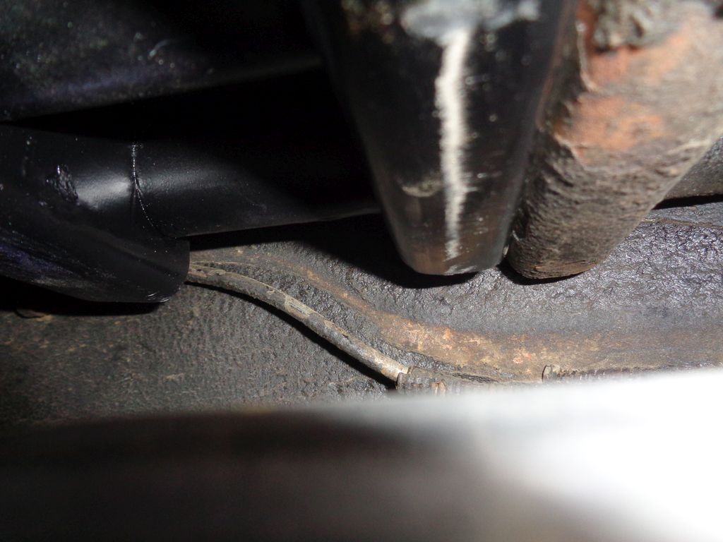
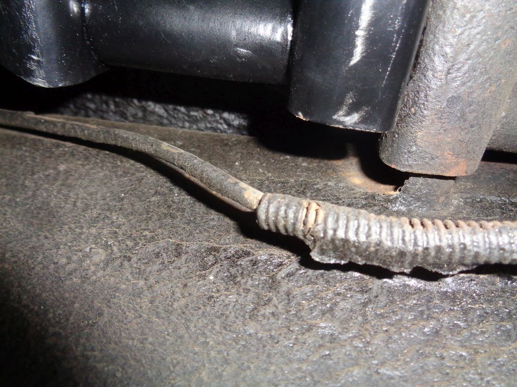
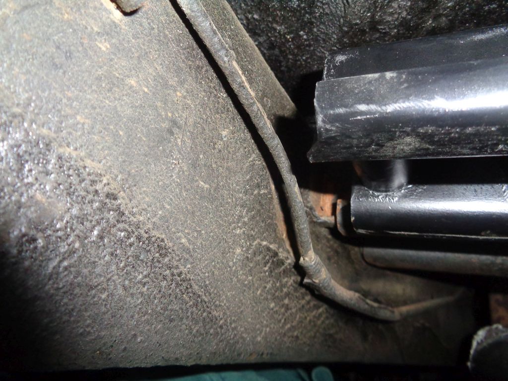
Then I noticed (or re-noticed that there might be an issue with the brake line. I think that the mounting plate will "slip" behind the brake line. If not the brake line will have to be recontoured (i.e. bent) to clear the new cross member mounting plate. At worst, I will need to install a new brake line. Oh no!! (LOL).
This is the situation that I discovered:
Edited by 56D500boy 2019-03-27 1:48 AM
 (New56DodgeTransCrossMemberAndConflictWithRearBrakeLine_1.jpg) (New56DodgeTransCrossMemberAndConflictWithRearBrakeLine_1.jpg)
 (New56DodgeTransCrossMemberAndConflictWithRearBrakeLine_2.jpg) (New56DodgeTransCrossMemberAndConflictWithRearBrakeLine_2.jpg)
 (New56DodgeTransCrossMemberAndConflictWithRearBrakeLine_3.jpg) (New56DodgeTransCrossMemberAndConflictWithRearBrakeLine_3.jpg)
Attachments
----------------
 New56DodgeTransCrossMemberAndConflictWithRearBrakeLine_1.jpg (109KB - 418 downloads) New56DodgeTransCrossMemberAndConflictWithRearBrakeLine_1.jpg (109KB - 418 downloads)
 New56DodgeTransCrossMemberAndConflictWithRearBrakeLine_2.jpg (178KB - 413 downloads) New56DodgeTransCrossMemberAndConflictWithRearBrakeLine_2.jpg (178KB - 413 downloads)
 New56DodgeTransCrossMemberAndConflictWithRearBrakeLine_3.jpg (160KB - 421 downloads) New56DodgeTransCrossMemberAndConflictWithRearBrakeLine_3.jpg (160KB - 421 downloads)
|
|
| |
|
   
Location: North Australia | Dave, did you consider modifying the cross member instead of moving the 'mounting ears'? By this I mean cutting the member where the box mounts and plating it with the holes in the new position.
This might be a better/easier solution for you.
Steve. |
|
| |
|

Expert 5K+
Posts: 9904
       
Location: Lower Mainland BC | 60 Imp - 2019-03-27 1:28 PM
Dave, did you consider modifying the cross member instead of moving the 'mounting ears'? By this I mean cutting the member where the box mounts and plating it with the holes in the new position.
This might be a better/easier solution for you.
Steve.
Thanks Steve. I am looking for easier solutions but one of my criteria is that this conversion by completely reversible, i.e. the original cross member mounting ears stay in place, no mods.
The main issue with the TorqueFlite is the size of the transmission oil pan. It would literally bump into the existing cross member unless the cross member was moved back or significantly modified. I think that modification would be a big section cut out of the middle of the cross member and an a big "U" fabricated that would attach to and cantilever rearwards for the cut cross member. It would be twisty and springy unless some serious metals was involved. Probably easier to stick with Plan A.
 |
|
| |
|
Veteran
Posts: 210
 
Location: Suwanee, GA | Have you thought about acquiring another cross member (to save the original) and sectioned it 3/8" about ~5" from each end? Then weld 3/8" X 3" X 6" or however long to each of the end pieces and weld the center section however far offset was required. That way you could retain your existing mounts, get around your brake line, avoid issues with trans pan, and revert back whenever you wanted. You don't have far to move it, and the engine mounts will handle the majority of the torque anyway. Plus, no welding underneath the car. |
|
| |
|

Expert 5K+
Posts: 9904
       
Location: Lower Mainland BC | Ev's62Chrysler - 2019-03-27 3:48 PM
Have you thought about acquiring another cross member (to save the original) and sectioned it 3/8" about ~5" from each end? Then weld 3/8" X 3" X 6" or however long to each of the end pieces and weld the center section however far offset was required. That way you could retain your existing mounts, get around your brake line, avoid issues with trans pan, and revert back whenever you wanted. You don't have far to move it, and the engine mounts will handle the majority of the torque anyway. Plus, no welding underneath the car.
I'm not sure if I follow what you are saying. I already have a 2nd cross member (the black painted one in the photos). I think what you are trying to suggest is the same as my "U" idea (??). Sketches would be handy.
 |
|
| |
|

Veteran
Posts: 210
 
Location: Suwanee, GA | Attached.
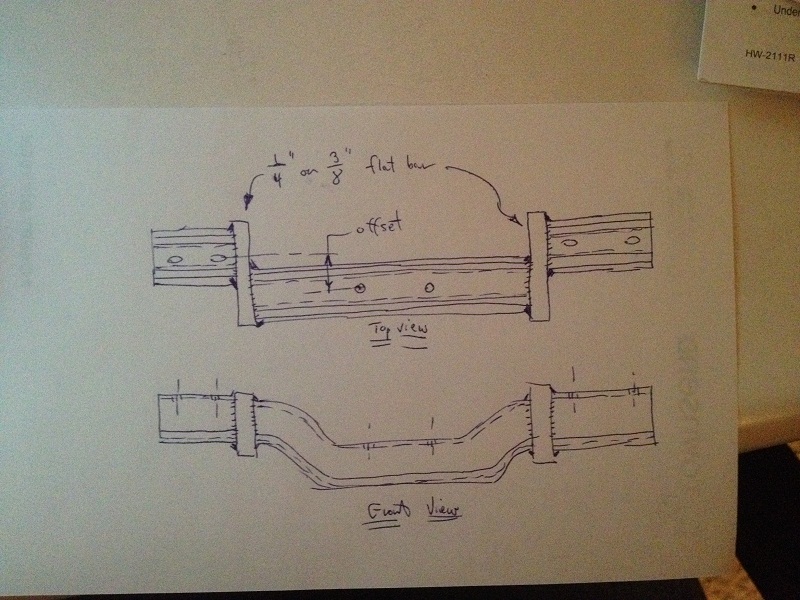 (IMG_7916.JPG) (IMG_7916.JPG)
Attachments
----------------
 IMG_7916.JPG (191KB - 388 downloads) IMG_7916.JPG (191KB - 388 downloads)
|
|
| |
|

Expert 5K+
Posts: 9904
       
Location: Lower Mainland BC | Ev's62Chrysler - 2019-03-28 7:58 PM
Attached.
Robert: Very nice. Thank you.
It is my "U" but it is much more elegant than what I was thinking. 
I will run it by my neighbour who is a fabricator by trade (and who will be doing the welding regardless of which design wins).

|
|
| |
|

Expert 5K+
Posts: 9672
      
Location: So. Cal | When I put a 700R4 trans into my '56 Plymouth, I left the frame mounts alone and modified the crossmember as suggested too, except that I just used 1/8" plate instead of the thick 1/4" suggested. I think that thick plate is only required if the offset is much larger than the width of the crossmember.
Edited by Powerflite 2019-03-29 9:25 AM
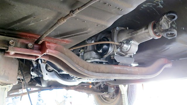 (700R4Trans.jpg) (700R4Trans.jpg)
Attachments
----------------
 700R4Trans.jpg (47KB - 396 downloads) 700R4Trans.jpg (47KB - 396 downloads)
|
|
| |
|

Expert 5K+
Posts: 9904
       
Location: Lower Mainland BC | Powerflite - 2019-03-29 6:22 AM
When I put a 700R4 trans into my '56 Plymouth, I left the frame mounts alone and modified the crossmember as suggested too, except that I just used 1/8" plate instead of the thick 1/4" suggested. I think that thick plate is only required if the offset is much larger than the width of the crossmember.
Thanks Nathan. Corroborates what Robert was suggesting in his sketch. Not sure about just the 1/8" plate but I see that the offset is minimal. I think I would have added a bolt-on offset plate (like a "spring board" - maybe with gussets that dropped down to the side of the OE cross-member to resist the twist/sag that could occur) in the middle of the cross member and left the cross member alone for that small offset.
I thought about it for my project until I realized that the issue is NOT the mount as much as the transmission oil pan.

Edited by 56D500boy 2019-03-29 2:23 PM
|
|
| |
|

Expert 5K+
Posts: 9672
      
Location: So. Cal | That's the same reason why I did it the way I did.  It's not so much that the mount is in the wrong spot as much as the crossmember was in the way of the oil pan. By the way, I moved my crossmember two inches back. I'm not sure how far you need to go. It's not so much that the mount is in the wrong spot as much as the crossmember was in the way of the oil pan. By the way, I moved my crossmember two inches back. I'm not sure how far you need to go.
Edited by Powerflite 2019-03-29 3:20 PM
|
|
| |
|

Expert 5K+
Posts: 9672
      
Location: So. Cal | By-the-way, if I were to do my setup all over again, I would install a '62-'65 aluminum 727 instead. That way you get a park function on the trans that you can activate with a cable and it's still fully compatible with the push buttons. You would just need to use an adapter on the motor to mount it up. You can also get one with the E-brake on the back or without it, with a normal slip joint too if you like. Just a thought before you get too far into it. I REALLY enjoy having the park function on this trans. When you have a loaded trailer with a loaded car, parked on a mountain side, having a park function is really nice.
Edited by Powerflite 2019-03-29 3:30 PM
|
|
| |
|

Expert 5K+
Posts: 9904
       
Location: Lower Mainland BC | Powerflite - 2019-03-29 12:26 PM
By-the-way, if I were to do my setup all over again, I would install a '62-'65 aluminum 727 instead.
I appreciate the suggestion but I did know about that alternative. Dave H. in Minnesota did that with his 56 350 hp 2 x 4bbl "warmed over" D500 hemi. He gave me a copy of his 9 page DIY instructions to convert to a 727. However, after reading that twice, I decided that it was a lot of work (too much for me). Besides, I have it in my mind that if the late build 56 Dodges were being lined up to get the torqueflites (and there are several signs that they were) the D500s would have likely been the most likely candidates. The transmission that they would have used would have used would have been a cast-iron A-466 from the upcoming 57 Chryslers. The only debate that I have going on (in my head) is whether they would have used an oil-cooled or air-cooled torqueflite. The Windsors with the 354 Spitfire polys with a 4 bbl supposedly made 285 hp (265 with the 2 bbl) which should have been enough for a 56 D500 and maybe even a D500-1. The 57 Windsor torqueflites were air-cooled. As it happens (how convenient) that is what I have. That said this past Monday I thought I was lucking into a 58 Dodge D100 truck Loadflite (which was the same as the 57-58 New Yorker and Imperial torqueflites). They were oil-cooled and I would have rationalized that the D500 warranted an oil-cooled torqueflite. Unfortunately, the transmission turned out to be an oil-cooled PowerFlite. 
But thanks again.
 |
|
| |
|
Extreme Veteran
Posts: 371
    
| Isn't re-engineering and geometry fun? Reminds me all too well of when the net did not exist and all you had was all who might have an idea. My '60 fury was a nightmare when it came to the trans mount going from the auto to the manual. If only the brake and pedal assembly was as easy, not. |
|
| |
|

Expert 5K+
Posts: 9904
       
Location: Lower Mainland BC | .
Thanks for the suggestions regarding the slice and offset. Since the offset is going to be about 3.5" to 4" and the width of the cross-member is about that, a slice and offset solution will put a lot of twist on the existing mounting ears. So for now, I am pursuing new mounting ears (made from the 3" square tubing), welded to 1/8" steel plate that is attached to the frame via either nut-serts and bolts or welding or both.
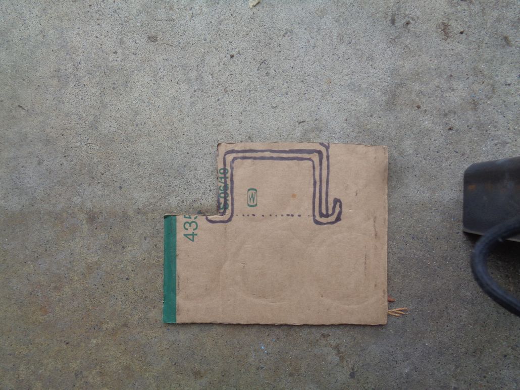
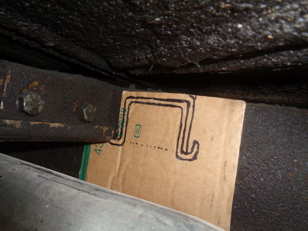
Yesterday, I was in the garage under the driver's side of the car and developed a template for the mounting plate out of cardboard. Today I got the car out and investigated the passenger side mount.
Should be easier - no brake line in the way (not that that will be a major deal on the driver's side).
I flipped yesterday's template over and marked it up showing where the ear would go and where the cross member would slip into the underside of the ear. The rest of the plate would be available for three or four mounting bolts. I sized the plate to be as tall as the frame and 6" wide (I bought a piece of 1/8" plate that was 6" x 12" some time ago).
While I was out there testing things out, I loosened and removed the two bolts that hold the existing transmission cross-member the OE mounting ears. Just so you know, at least on a 56 Dodge, the nut end of the bolt is 11/16" and the head of the bolt is 5/8". Very little room to get a good purchase to get the bolts/nuts loose - especially for the one closest to the frame rail.
Note: This is just a concept. I haven't cut the 6" x 12" plate yet. I can make the mounting plate smaller than the conceptual template.
Note 2: I am going on the idea that whatever I do, it will be reversible back to stock. As a result, the existing transmission mounting ears will remain in place. This results in the need for a notch in the mounting plate(s) for the new cross member

Here are some photos from today:
Edited by 56D500boy 2019-10-06 9:33 PM
 (ConceptForTorquefliteCrossMemberMountingPlate_WithoutEar.jpg) (ConceptForTorquefliteCrossMemberMountingPlate_WithoutEar.jpg)
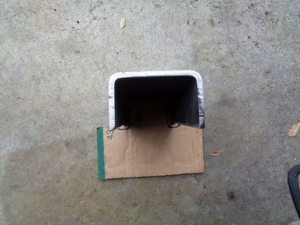 (ConceptForTorquefliteCrossMemberMountingPlate_WithEar_Outside.jpg) (ConceptForTorquefliteCrossMemberMountingPlate_WithEar_Outside.jpg)
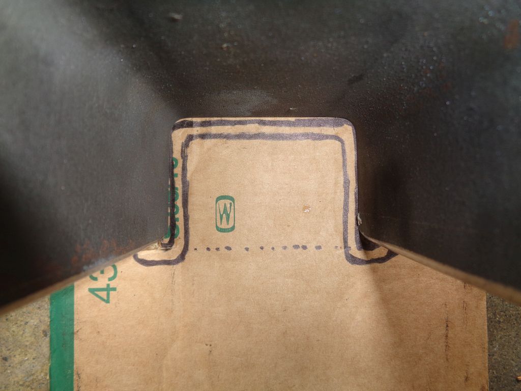 (ConceptForTorquefliteCrossMemberMountingPlate_WithEar_Inside.jpg) (ConceptForTorquefliteCrossMemberMountingPlate_WithEar_Inside.jpg)
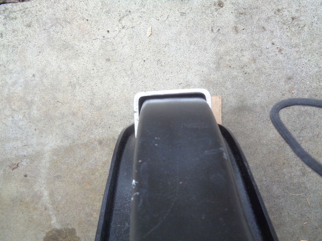 (ConceptForTorquefliteCrossMemberMountingPlate_WithEarAndCrossMember_Outside.jpg) (ConceptForTorquefliteCrossMemberMountingPlate_WithEarAndCrossMember_Outside.jpg)
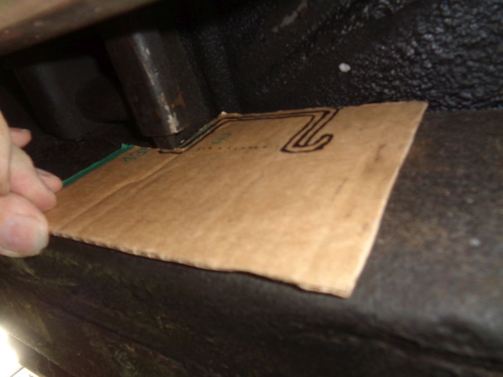 (ConceptForTorquefliteCrossMemberMountingPlate_WithoutEar_TrialFit_1.jpg) (ConceptForTorquefliteCrossMemberMountingPlate_WithoutEar_TrialFit_1.jpg)
 (ConceptForTorquefliteCrossMemberMountingPlate_WithoutEar_TrialFit_2.jpg) (ConceptForTorquefliteCrossMemberMountingPlate_WithoutEar_TrialFit_2.jpg)
Attachments
----------------
 ConceptForTorquefliteCrossMemberMountingPlate_WithoutEar.jpg (162KB - 345 downloads) ConceptForTorquefliteCrossMemberMountingPlate_WithoutEar.jpg (162KB - 345 downloads)
 ConceptForTorquefliteCrossMemberMountingPlate_WithEar_Outside.jpg (160KB - 369 downloads) ConceptForTorquefliteCrossMemberMountingPlate_WithEar_Outside.jpg (160KB - 369 downloads)
 ConceptForTorquefliteCrossMemberMountingPlate_WithEar_Inside.jpg (104KB - 366 downloads) ConceptForTorquefliteCrossMemberMountingPlate_WithEar_Inside.jpg (104KB - 366 downloads)
 ConceptForTorquefliteCrossMemberMountingPlate_WithEarAndCrossMember_Outside.jpg (168KB - 372 downloads) ConceptForTorquefliteCrossMemberMountingPlate_WithEarAndCrossMember_Outside.jpg (168KB - 372 downloads)
 ConceptForTorquefliteCrossMemberMountingPlate_WithoutEar_TrialFit_1.jpg (77KB - 367 downloads) ConceptForTorquefliteCrossMemberMountingPlate_WithoutEar_TrialFit_1.jpg (77KB - 367 downloads)
 ConceptForTorquefliteCrossMemberMountingPlate_WithoutEar_TrialFit_2.jpg (135KB - 388 downloads) ConceptForTorquefliteCrossMemberMountingPlate_WithoutEar_TrialFit_2.jpg (135KB - 388 downloads)
|
|
| |
|

Expert 5K+
Posts: 9904
       
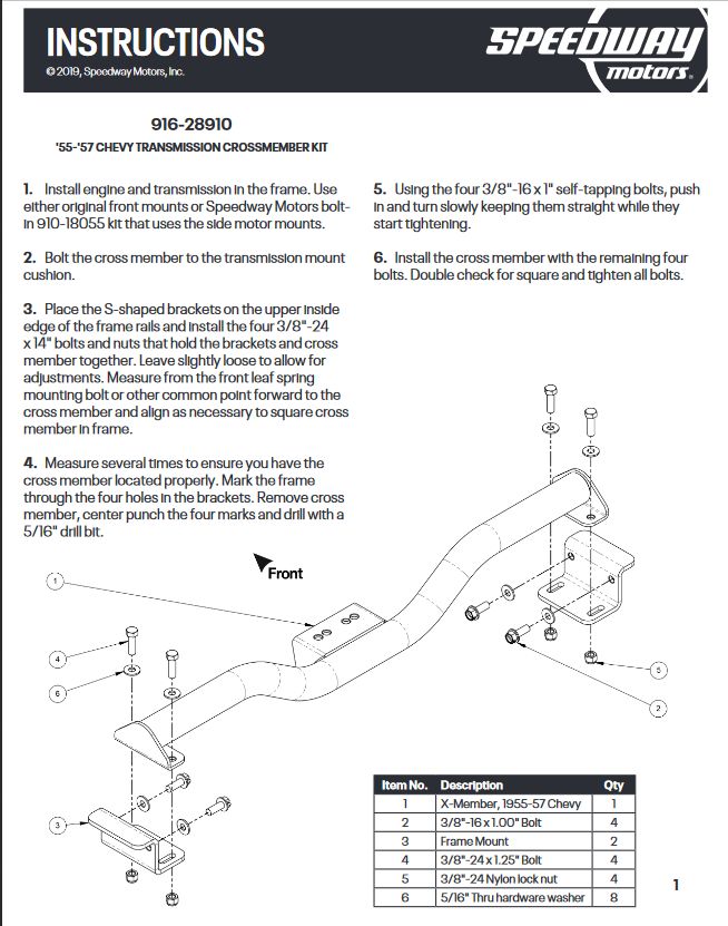
Location: Lower Mainland BC | After speaking to my fabricator neighbour about the welding required for my "Plan A", I had a poke around the internet for no-weld options. Found a couple of transmission mount kits for 55-57 Chevies that provide some inspiration, i.e. bent "hanger style" mounting brackets that get some weight holding strength from a tab that sits on the top of the frame and the remainder from two (per side) 3/8"-16 x 1.00" self-tapping bolts. I wouldn't be able to use the Chevy kits but I could use the idea to bend some brackets out of steel (or get them bent) and then use the "spare" OE Dodge cross-member (as planned) but bolting in downwards to the new brackets. (Brackets might want gussets).
I could do a mock-up out of aluminum plate (easier for me to bend but not strong enough to work in reality).
I'll work on a sketch tomorrow. For now:


 (55-57ChevTransMountKitShowingNoWeldFrameMounts.jpg) (55-57ChevTransMountKitShowingNoWeldFrameMounts.jpg)
Attachments
----------------
 55-57ChevTransMountKitShowingNoWeldFrameMounts.jpg (94KB - 362 downloads) 55-57ChevTransMountKitShowingNoWeldFrameMounts.jpg (94KB - 362 downloads)
|
|
| |
|

Expert 5K+
Posts: 9904
       
Location: Lower Mainland BC | 56D500boy - 2019-10-06 11:01 PM
I wouldn't be able to use the Chevy kits but I could use the idea to bend some brackets out of steel (or get them bent) and then use the "spare" OE Dodge cross-member (as planned) but bolting in downwards to the new brackets. (Brackets might want gussets).
I could do a mock-up out of aluminum plate (easier for me to bend but not strong enough to work in reality). I'll work on a sketch tomorrow.
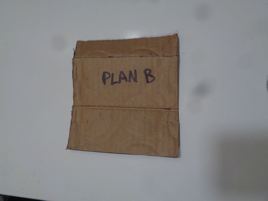
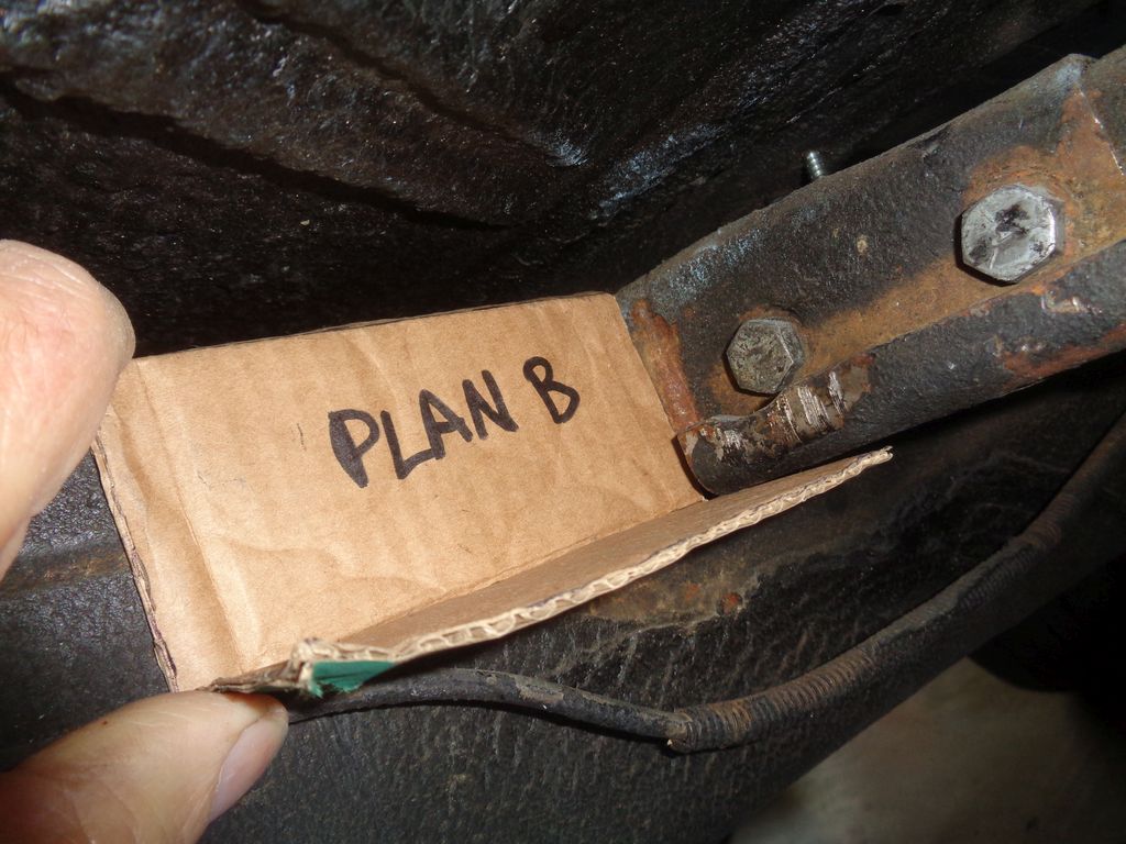
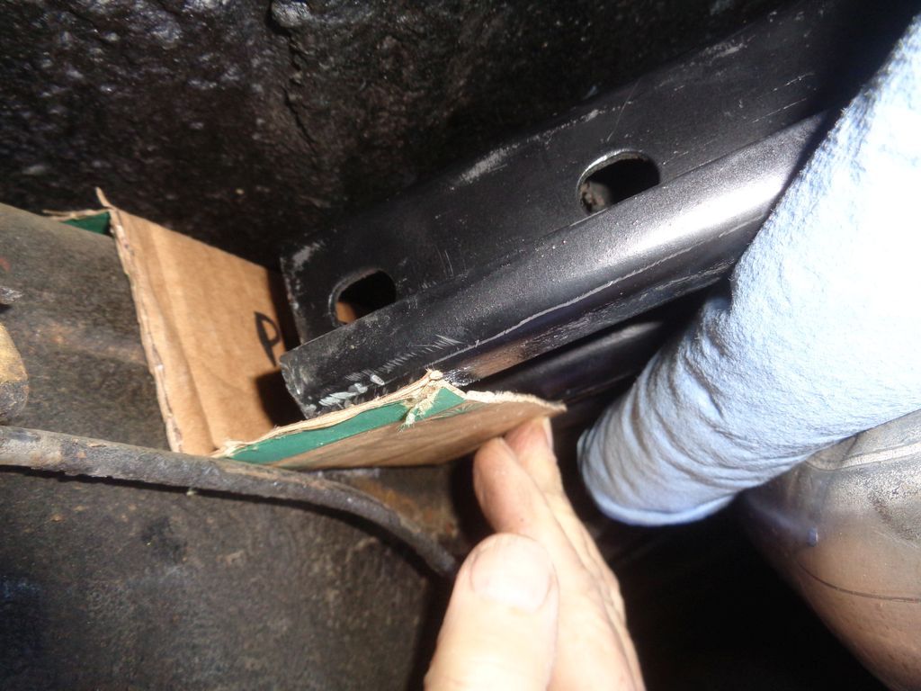
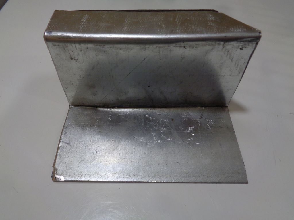
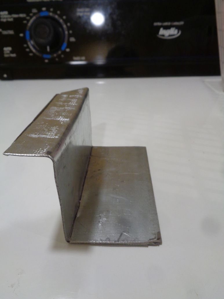
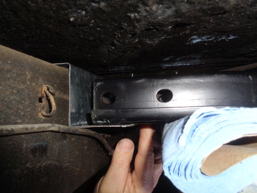
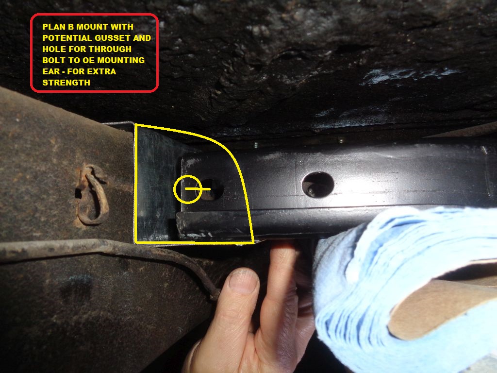
Forget the sketch. I went out to the car and drew a line in chalk (okay, soap) under the existing cross member to where the new mount will be and then measured down from the top of the frame to the line. Got about 2.25". Then I measure the width that I thought I needed (about 4.75"). Then I took a wild @ss guess at the needed length of the bottom (cantilevered) flange at about 2". Then I cut a mock-up out of cardboard and labeled it "Plan B". Then I went back out the car and got the new cross member sitting beside the existing crossmember and tried the Plan B - Mark 1 cardboard mock-up. Looks like it would work but that bottom flange is a bit short.
Decided to make a Mark 2 mock-up out of some 16 gauge galvanized that I had. Stayed with the original estimated dimensions but increased the bottom flange to 2.25" from 2". Cut it out with my angle grinder and zip blade and then banged it into shape in my vice (a bit too small for the job but I improvised). Then I took it out the car and gave it a go. Looks better. Probably a few more tweeks before I try to make it out of 1/8" steel plate (not sure how I will bend that). If I want to strengthen the bracket I could add gussets on both sides *and* if I am lucky it might be possible to put a hole in the gusset(s) that lines up with the outer hole in the existing frame "ears" and run a through bolt through the new bracket, the new cross member and the original ears (maybe).
Note: The little 45 deg champfer on the Mark 2 metal bracket has no purpose. The piece of scrap metal that I used had that cut from a previous project. 
Photos from today:
Edited by 56D500boy 2019-10-07 6:09 PM
 (PlanBMark1CardboardMockUp1inchUpperFlange2point25dropAnd2inchhorizontalFlange.jpg) (PlanBMark1CardboardMockUp1inchUpperFlange2point25dropAnd2inchhorizontalFlange.jpg)
 (PlanBMark1BracketTrial_1.jpg) (PlanBMark1BracketTrial_1.jpg)
 (PlanBMark1BracketTrial_WithNewCrossMemberInPosition.jpg) (PlanBMark1BracketTrial_WithNewCrossMemberInPosition.jpg)
 (PlanBMark2In16GaugeSteel_1.jpg) (PlanBMark2In16GaugeSteel_1.jpg)
 (PlanBMark2In16GaugeSteel_2.jpg) (PlanBMark2In16GaugeSteel_2.jpg)
 (PlanBMark2In16GaugeSteel_WithNewCrossMember.jpg) (PlanBMark2In16GaugeSteel_WithNewCrossMember.jpg)
 (PlanBMark2In16GaugeSteel_WithNewCrossMember_Annotated.jpg) (PlanBMark2In16GaugeSteel_WithNewCrossMember_Annotated.jpg)
Attachments
----------------
 PlanBMark1CardboardMockUp1inchUpperFlange2point25dropAnd2inchhorizontalFlange.jpg (52KB - 348 downloads) PlanBMark1CardboardMockUp1inchUpperFlange2point25dropAnd2inchhorizontalFlange.jpg (52KB - 348 downloads)
 PlanBMark1BracketTrial_1.jpg (143KB - 364 downloads) PlanBMark1BracketTrial_1.jpg (143KB - 364 downloads)
 PlanBMark1BracketTrial_WithNewCrossMemberInPosition.jpg (128KB - 365 downloads) PlanBMark1BracketTrial_WithNewCrossMemberInPosition.jpg (128KB - 365 downloads)
 PlanBMark2In16GaugeSteel_1.jpg (82KB - 355 downloads) PlanBMark2In16GaugeSteel_1.jpg (82KB - 355 downloads)
 PlanBMark2In16GaugeSteel_2.jpg (62KB - 375 downloads) PlanBMark2In16GaugeSteel_2.jpg (62KB - 375 downloads)
 PlanBMark2In16GaugeSteel_WithNewCrossMember.jpg (119KB - 348 downloads) PlanBMark2In16GaugeSteel_WithNewCrossMember.jpg (119KB - 348 downloads)
 PlanBMark2In16GaugeSteel_WithNewCrossMember_Annotated.jpg (211KB - 348 downloads) PlanBMark2In16GaugeSteel_WithNewCrossMember_Annotated.jpg (211KB - 348 downloads)
|
|
| |
|

Expert 5K+
Posts: 9904
       
Location: Lower Mainland BC | .
This morning, I took the galvanized 16 gauge mock-up and the spare/new cross member to the transmission shop who are going to be rebuilding the A-466 torqueflite (air cooled from a 57 Windsor) and who will do the install once the rebuild is complete (in a few days).
Regarding my bracket mock up, they basically said "That's nice. We'll take it from here". (They will either make real brackets based on the mock up out of 3/16" or 1/4" plate or come up with their own plan (with my approval)).
They know what they are doing (at least I think so) so I had to agree. 
We'll see soon.
Drove the 56 Dodge so they could see what the Torqueflite will be going into. Rained there and back but that was fine. Can't be scared of rain. 
 |
|
| |
|

Expert 5K+
Posts: 9904
       
Location: Lower Mainland BC | 56D500boy - 2019-10-08 10:30 PM
Regarding my bracket mock up, they basically said "That's nice. We'll take it from here". (They will either make real brackets based on the mock up out of 3/16" or 1/4" plate or come up with their own plan (with my approval ) ).
They know what they are doing (at least I think so ) so I had to agree. 
We'll see soon.
Soon. LOL. There have been issues along the way (surprise surprise)  but apparently the rebuilt torque converter and rebuilt A-466 are in the car (finally). but apparently the rebuilt torque converter and rebuilt A-466 are in the car (finally).  (They weren't last week when I took them a Torqueflite shift cable) (They weren't last week when I took them a Torqueflite shift cable)
I phoned after lunch and asked "How are things going?", as in "What new issue has cropped up that needs to be solved?" but the answer is "Fine, we're plugging away at it" (its not a priority job so they work on it when there is available time).
Fine.
An hour (or less) later, I get a phone call from the shop. "Um...our idea about welding the channel you gave us directly to the frame is not going to work. The "new" cross member bangs into the old bracket. How about this (and he proceeds to describe the offset bracket that reuses the existing mounts as Robert D. and Nathan had suggested previously). Could you come out tomorrow morning to discuss this?"
Why sure I can. (And my other ideas) 
Robert's and Nathan's previous input:
Robert's sketch:

Nathan's photo:

Edited by 56D500boy 2019-12-16 7:25 PM
|
|
| |
|

Expert 5K+
Posts: 9904
       
Location: Lower Mainland BC | 56D500boy - 2019-12-16 4:23 PM
An hour (or less) later, I get a phone call from the shop. "Um...our idea about welding the channel you gave us directly to the frame is not going to work. The "new" cross member bangs into the old bracket. How about this (and he proceeds to describe the offset bracket that reuses the existing mounts as Robert D. and Nathan had suggested previously). Could you come out tomorrow morning to discuss this?"
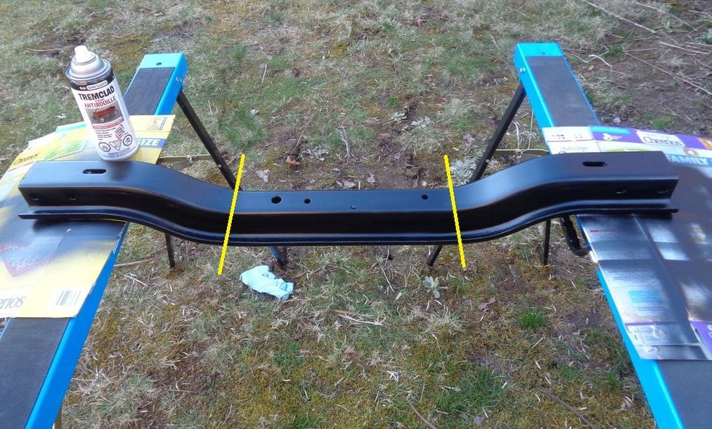
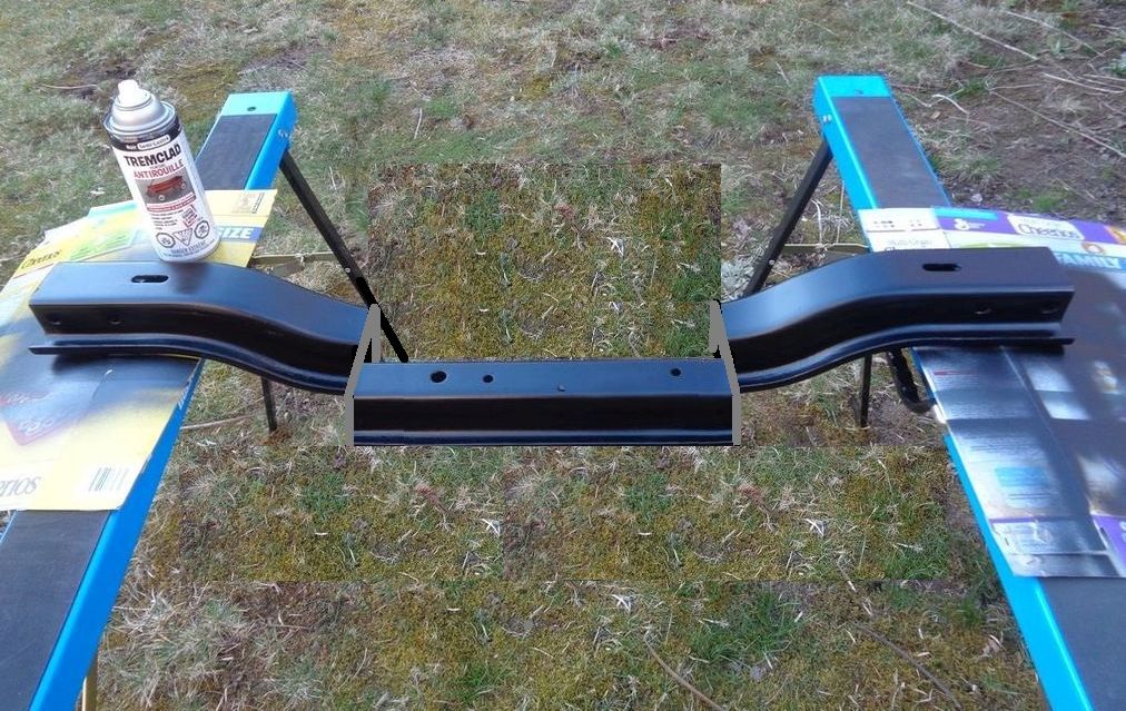
So I went out to the shop armed with photos of Robert's and Nathan's suggestions. Basically the same, except that the shop owner "Matt" suggested that the cuts be made down on the flats rather than up high. I agreed.
Their game plan now is to mark the "new" cross member and then cut it. And then mount the outer bits to the OE ears on the frame and the center bit to the transmission and then decide about the trimming for the thickness of the off-set plates and then get the welding done. Sounded good (enough) for me. (I think my ideas would have worked but they are telling me this will be the most cost effective plus the OE mounts stay and nothing new is welded to the frame. OK.
In the meantime, with the A-466 in the car, they measured the new driveshaft length requirements and sent it out for shortening.
There is a small possibility that I might get the car back before Christmas. In the meantime, it is a much warmer and drier place than my little 1942 12'x20' unheated garage. 
This is today's concept:
 (56DodgeTransmissionCrossMemberLikelyCutLocationForOffset.jpg) (56DodgeTransmissionCrossMemberLikelyCutLocationForOffset.jpg)
 (56DodgeTransmissionCrossMemberOffsetConceptPhotoShopMockUp.jpg) (56DodgeTransmissionCrossMemberOffsetConceptPhotoShopMockUp.jpg)
Attachments
----------------
 56DodgeTransmissionCrossMemberLikelyCutLocationForOffset.jpg (187KB - 366 downloads) 56DodgeTransmissionCrossMemberLikelyCutLocationForOffset.jpg (187KB - 366 downloads)
 56DodgeTransmissionCrossMemberOffsetConceptPhotoShopMockUp.jpg (200KB - 356 downloads) 56DodgeTransmissionCrossMemberOffsetConceptPhotoShopMockUp.jpg (200KB - 356 downloads)
|
|
| |
|

Expert 5K+
Posts: 9904
       
Location: Lower Mainland BC | 56D500boy - 2019-12-17 12:35 PM
So I went out to the shop armed with photos of Robert's and Nathan's suggestions. Basically the same, except that the shop owner "Matt" suggested that the cuts be made down on the flats rather than up high. I agreed.
Their game plan now is to mark the "new" cross member and then cut it. And then mount the outer bits to the OE ears on the frame and the center bit to the transmission and then decide about the trimming for the thickness of the off-set plates and then get the welding done.
In the meantime, with the A-466 in the car, they measured the new driveshaft length requirements and sent it out for shortening.
There is a small possibility that I might get the car back before Christmas. In the meantime, it is a much warmer and drier place than my little 1942 12'x20' unheated garage. 
Well that was the plan. Reality was different 
I did phone back to the shop on Dec. 17th and suggested that the "down on the flats" idea, while, good, was going to be problematic if there was interference with transmission pan. I checked with them before Christmas and nothing had happened. I was told "in the New Year".
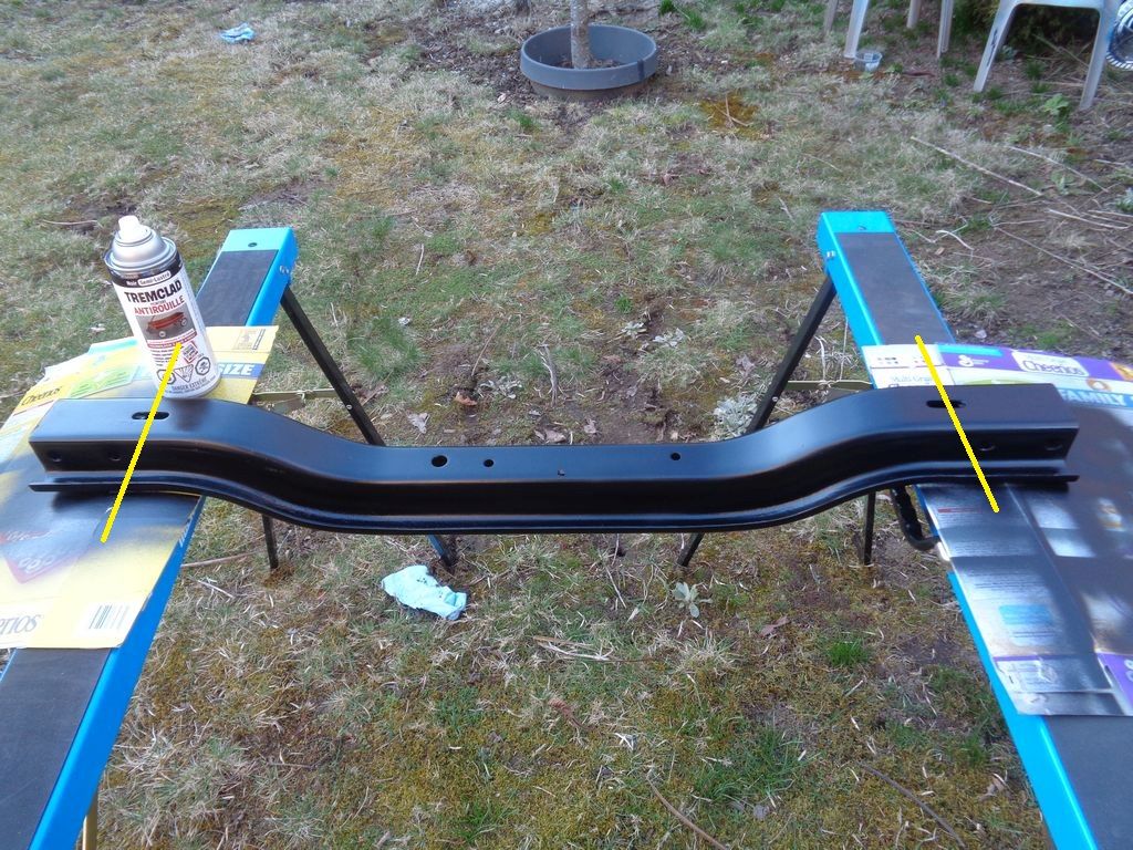
I went out to the shop today (Jan. 6th) to check on progress. The "new" cross-member has been cut in prep for the welding but the cut was not "down on the flats". It's up high (and firm - to quote Bob Seeger - out of context) because, as suspected, "down low" didn't clear the Torqueflite pan (it did on one side but not the other). Not surprising that Plan C has now morphed to Plan D.
I am *told* that the machine shop's welder won't work in the transmission shop so the car has to be taken to the machine shop (a block away) for the cross member welding). That is *supposed* to happen in the next day or so. (Right).
The good news (I hope) is the drive shaft has been shortened and is back. It lost the OE taper (at the rear diff end). Not perfect but whatchagonnado?
So here is the revised plan for the cross member:
 (56DodgeTransmissionCrossMemberLikelyCutLocationForOffset_Rev2.jpg) (56DodgeTransmissionCrossMemberLikelyCutLocationForOffset_Rev2.jpg)
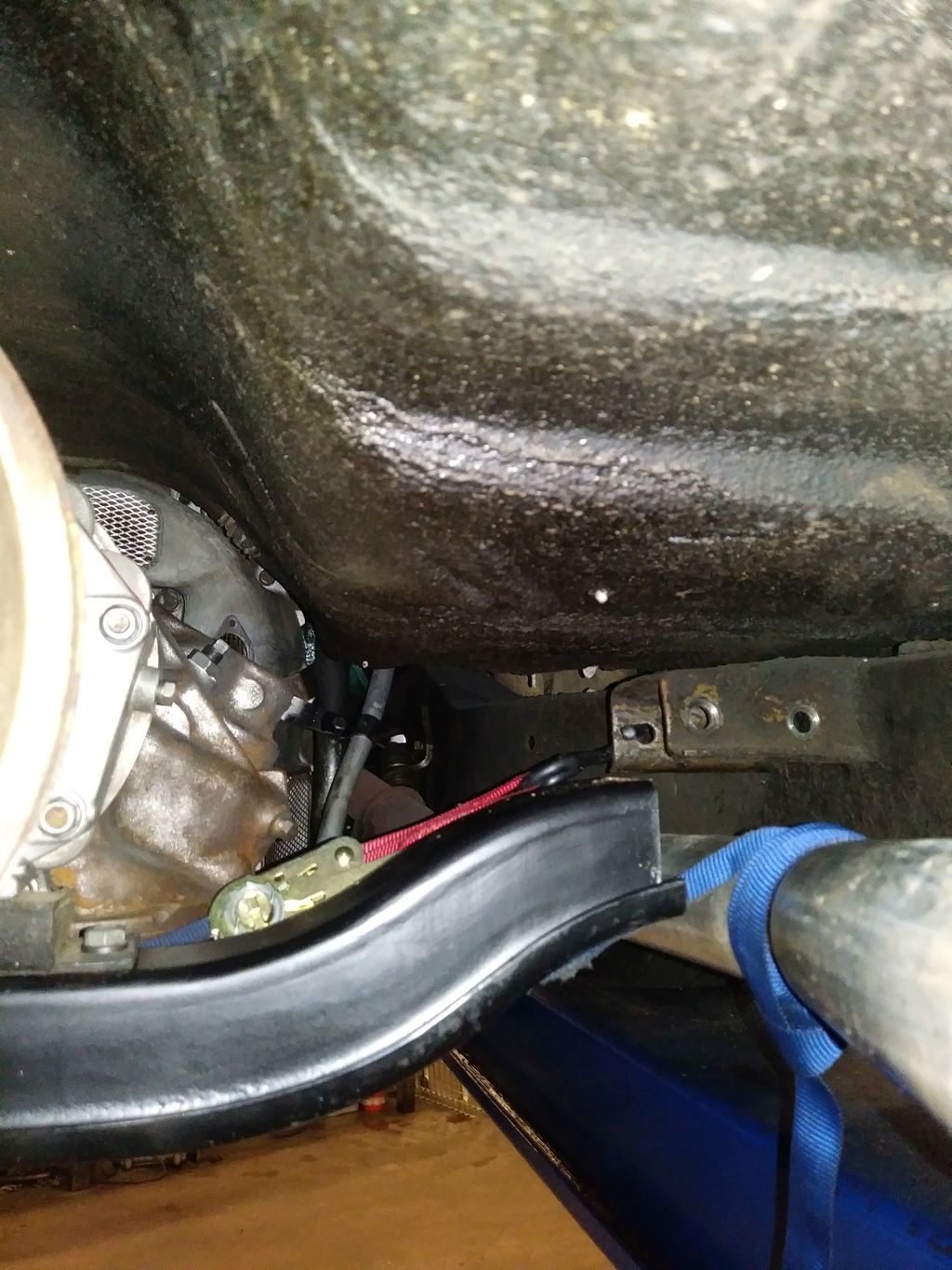 (RevisedCrossMemberCut_inTheCar.jpg) (RevisedCrossMemberCut_inTheCar.jpg)
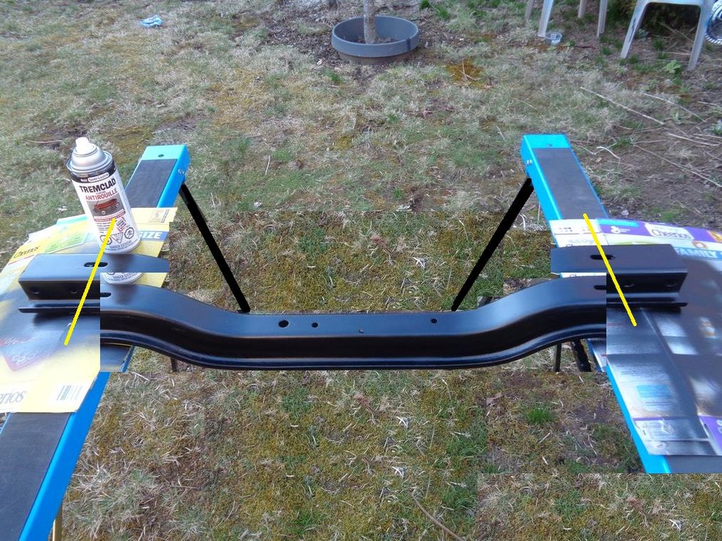 (56DodgeTransmissionCrossMemberOffsetConceptPhotoShopMockUp_Rev2.jpg) (56DodgeTransmissionCrossMemberOffsetConceptPhotoShopMockUp_Rev2.jpg)
Attachments
----------------
 56DodgeTransmissionCrossMemberLikelyCutLocationForOffset_Rev2.jpg (237KB - 353 downloads) 56DodgeTransmissionCrossMemberLikelyCutLocationForOffset_Rev2.jpg (237KB - 353 downloads)
 RevisedCrossMemberCut_inTheCar.jpg (221KB - 351 downloads) RevisedCrossMemberCut_inTheCar.jpg (221KB - 351 downloads)
 56DodgeTransmissionCrossMemberOffsetConceptPhotoShopMockUp_Rev2.jpg (233KB - 362 downloads) 56DodgeTransmissionCrossMemberOffsetConceptPhotoShopMockUp_Rev2.jpg (233KB - 362 downloads)
|
|
| |
|

Expert 5K+
Posts: 9672
      
Location: So. Cal | I recommend you purchase a welder. Every time I have to pay someone to do something for me, I am reminded why I end up doing everything myself. I'm paying for a simple valve job on the heads of my 331 right now and it's no end of trouble. |
|
| |
|

Expert 5K+
Posts: 9904
       
Location: Lower Mainland BC | Powerflite - 2020-01-06 4:07 PM
I recommend you purchase a welder. Every time I have to pay someone to do something for me, I am reminded why I end up doing everything myself.
I can't disagree, at least about trying to do everything by yourself because there *ALWAYS* (Why?) issues when somebody else does it for you. In this case, I should have made the "Plan C" brackets and modified the front edge of the "new" cross-member (for clearance against the old "ear") and told them to use them. It was a mistake to let them do it (because "they know better") (they didn't).
On the welder suggestion, up until December, I didn't even have rear power in my 1942 12 x 20 single car garage (just a 12 gauge extension cord from the house to run a few things). However, I now have 40 amps and a breaker panel to play with - so the possibility of a small welder is now real(er). That said, my neighbour across the street's day job is professional welder/fabricator. He will (and has) done work for me using his home MIG (TIG?) welder. He works for beer (good beer). And I have *never* welded. Not even in high school even though I took all the shop classes offered (at least in Grades 9 and 10).

Edited by 56D500boy 2020-01-08 8:47 AM
|
|
| |
|

Expert 5K+
Posts: 7401
     
Location: northern germany |
Powerflite - 2020-01-06 4:07 PM
Every time I have to pay someone to do something for me, I am reminded why I end up doing everything myself.
How true! |
|
| |
|

Expert 5K+
Posts: 9904
       
Location: Lower Mainland BC | .
Got the car back today. Way too much money for the benefits. Oh well.
Plan A was making new mounting ears on plates and mounting the plates and ears to the frame rails behind the original OE ears. The transmission shop didn't like that one.
Plan B was making two-bend "shelf" brackets and mounting them to the frame rails (with 1/2" self-threading metal screws) and then mounting the cross member to the shelf brackets with bolts. Transmission shop didn't like that either.
So they came up with a solution that cut a middle section out of the cross member and then sliding it back and welding the center section to the outer bits (that were mounted to the OE ears) - with metal plates to joint the outer section to the middle section. That was my Plan C. I showed them the diagrams and photos that Robert and Nathan provided earlier and the transmission shop liked it. Kept telling me "That's what Corvettes have". I wasn't buying it but I had no choice. The transmission shop had to out source the welding and even had to have the car flat decked to the fab shop so the bits could be tacked together in place. Presumably the final welding was done on a welding bench at the fab shop.
The end result was absurdly expensive (the trans shop didn't really care, they mark whatever it was up by 15% so the more the better for them. Unfortunately, was not better for me  ). ).
The Plan C cross-member arrived back in the car already painted so I can't even inspect the welds when I saw it a week or so ago. When I first saw the sectioned mount, I decided that some point in the near future (spring) I would get the Plan B brackets made and go that way using the original cross member (which is uncut/intact). However, now, after spending all that money on the Plan C cross member, I don't know if I will bother with Plan B (and spend more money).
I think I will just focus on cosmetic improvements for awhile. This kind of blew the budget.  
The final bracket, in place with the 1957 Chrysler Windsor air-cooled A-466 cast iron TF.
Edited by 56D500boy 2020-01-21 1:54 AM
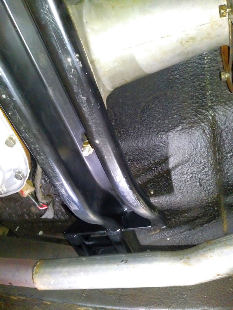 (Modified56DodgePFCrossMemberSectionedAndWeldedToMountTFTrans_PassengerSide.jpg) (Modified56DodgePFCrossMemberSectionedAndWeldedToMountTFTrans_PassengerSide.jpg)
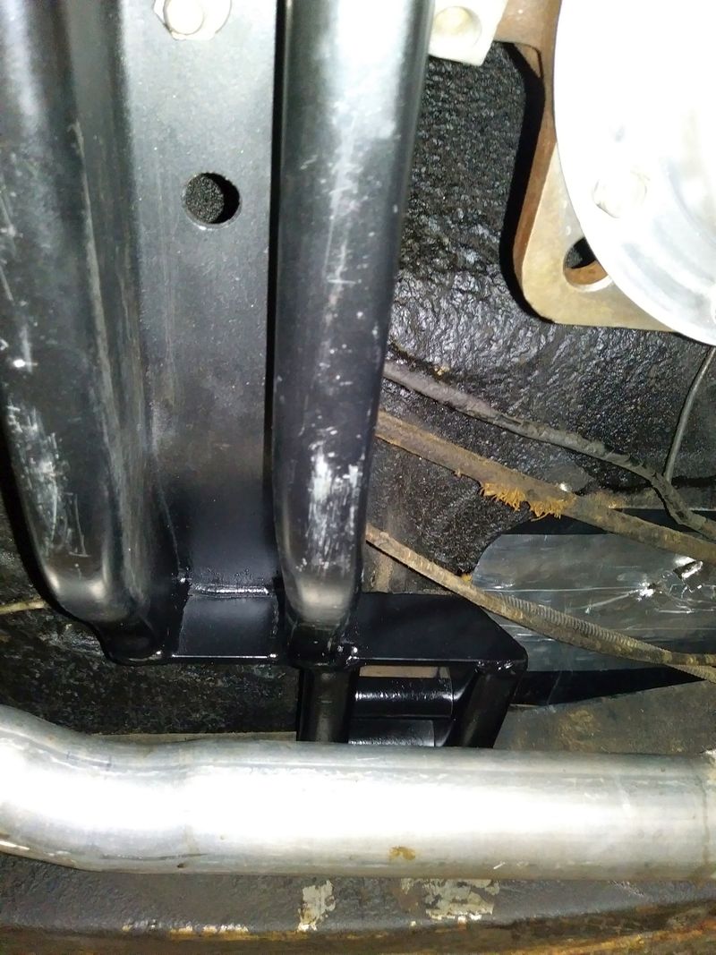 (Modified56DodgePFCrossMemberSectionedAndWeldedToMountTFTrans_DriversSide.jpg) (Modified56DodgePFCrossMemberSectionedAndWeldedToMountTFTrans_DriversSide.jpg)
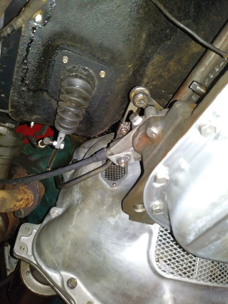 (56DodgeV8WithAirCooled57ChryslerWindsorTF.jpg) (56DodgeV8WithAirCooled57ChryslerWindsorTF.jpg)
Attachments
----------------
 Modified56DodgePFCrossMemberSectionedAndWeldedToMountTFTrans_PassengerSide.jpg (161KB - 348 downloads) Modified56DodgePFCrossMemberSectionedAndWeldedToMountTFTrans_PassengerSide.jpg (161KB - 348 downloads)
 Modified56DodgePFCrossMemberSectionedAndWeldedToMountTFTrans_DriversSide.jpg (165KB - 336 downloads) Modified56DodgePFCrossMemberSectionedAndWeldedToMountTFTrans_DriversSide.jpg (165KB - 336 downloads)
 56DodgeV8WithAirCooled57ChryslerWindsorTF.jpg (171KB - 374 downloads) 56DodgeV8WithAirCooled57ChryslerWindsorTF.jpg (171KB - 374 downloads)
|
|
| |
|
Expert
Posts: 2289
     
Location: Eastern Iowa | Dave
CCC
Custom by Cobble Craft!!
No, seriously, seems to me that they wanted NOTHING to do with WELDING to the FRAME!!
That's what its looking like to me
Reminds me of the hassle I went through back in '64 when I was talked into installing a 3 speed stick in my D-500.
And paying for it on a PFC's salery!!
|
|
| |
|

Expert 5K+
Posts: 9904
       
Location: Lower Mainland BC | finsruskw - 2020-02-05 7:59 AM
Dave
CCC
Custom by Cobble Craft!!
No, seriously, seems to me that they wanted NOTHING to do with WELDING to the FRAME!!
That's what its looking like to me
I can't disagree but my Plan B did not involve ANY welding what so ever. Would have been similar to this (except the cross member would have been the OE cross member):

I should have bought one of those, just to use the side brackets and hardware. Would have saved me $$$. 
 |
|
| |
|

Expert 5K+
Posts: 9904
       
Location: Lower Mainland BC | .
Again, in retrospect, I would have bought a transmission cross member from Southwest Speed and made it work. Way way less money than what I ended up paying to have my OE crossmember hacked and modified. 
https://www.southwestspeed.com/?sec=view_menu&cat=Suspension&sub=Cro...
Edited by 56D500boy 2022-11-21 2:52 PM
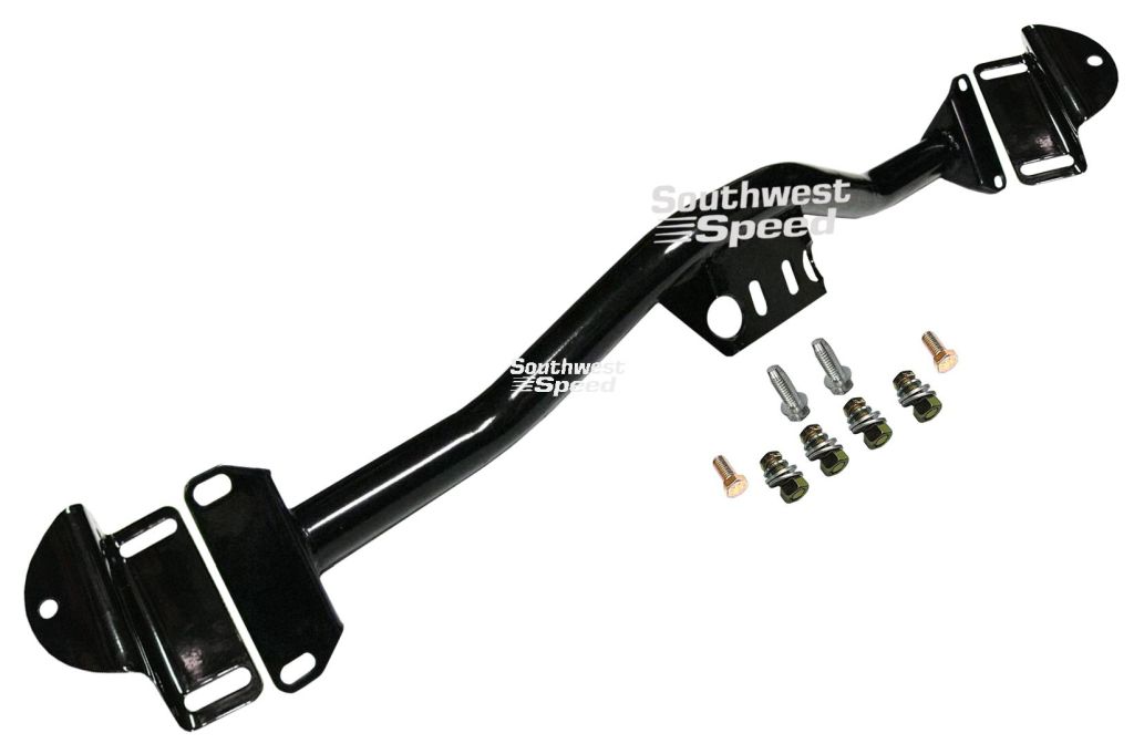 (SouthWestSpeedChevy_TriFive_crossmember.jpg) (SouthWestSpeedChevy_TriFive_crossmember.jpg)
 (SouthWestSpeedChevyTruckCrossmember.jpg) (SouthWestSpeedChevyTruckCrossmember.jpg)
Attachments
----------------
 SouthWestSpeedChevy_TriFive_crossmember.jpg (40KB - 93 downloads) SouthWestSpeedChevy_TriFive_crossmember.jpg (40KB - 93 downloads)
 SouthWestSpeedChevyTruckCrossmember.jpg (20KB - 90 downloads) SouthWestSpeedChevyTruckCrossmember.jpg (20KB - 90 downloads)
|
|
| |
|

Expert 5K+
Posts: 9904
       
Location: Lower Mainland BC | .
I had previously been sent a photo of a 56 Plymouth with a Powerflite that supposedly had a set or alternative slots for mounting the OE transmission cross member mounting ears further back,
i.e. like you would need if you were going to mount a longer transmission, like the Torqueflite. The photo that I had was dark and murky so I let it go.
HOWEVER, today Powerflite (Nathan N.) posted a link to a 56 Belvedere on BAT. In the BAT photos, there were a few interesting under carriage photos, including this one (why oh why didn't my
56 Dodge have those extra slots when I was swapping in an A-466 Torqueflite (???)).
https://bringatrailer.com/listing/1956-plymouth-belvedere-2/
These: (Previous photo first and then today's):
Edited by 56D500boy 2022-12-08 6:12 PM
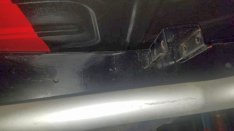 (MountingEarsShowingAlternativeLocationSlotsOnFrame.jpg) (MountingEarsShowingAlternativeLocationSlotsOnFrame.jpg)
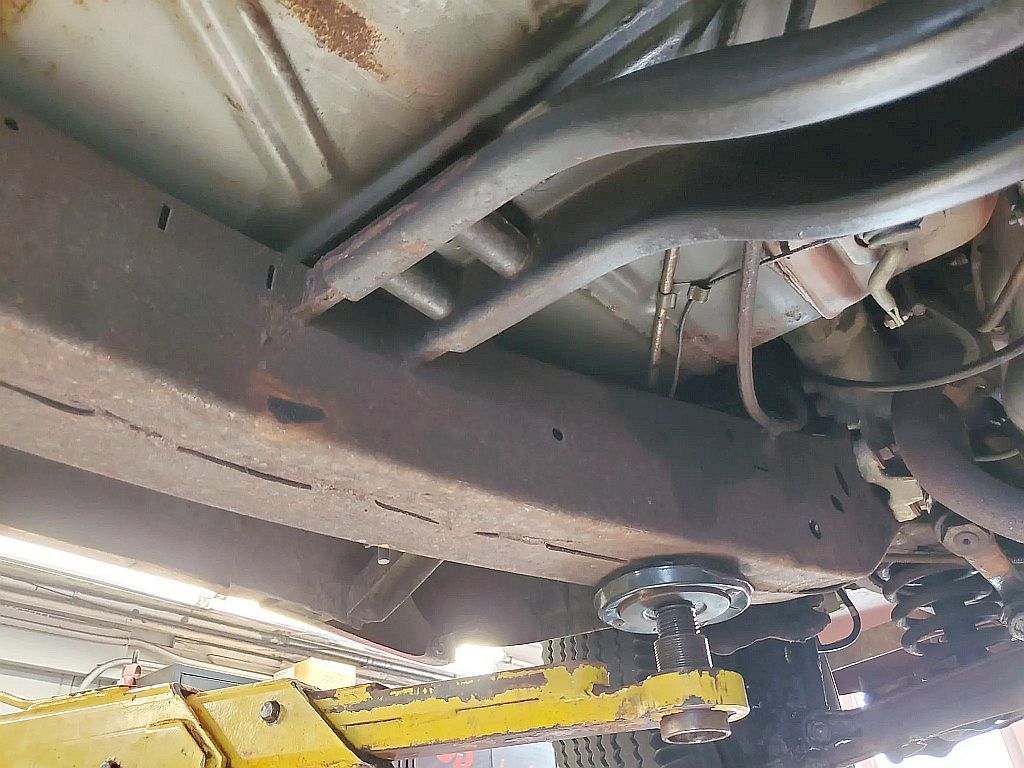 (MountingEarsShowingAlternativeLocationSlotsOnFrame_2_56PlymouthPowerflite.jpg) (MountingEarsShowingAlternativeLocationSlotsOnFrame_2_56PlymouthPowerflite.jpg)
Attachments
----------------
 MountingEarsShowingAlternativeLocationSlotsOnFrame.jpg (31KB - 80 downloads) MountingEarsShowingAlternativeLocationSlotsOnFrame.jpg (31KB - 80 downloads)
 MountingEarsShowingAlternativeLocationSlotsOnFrame_2_56PlymouthPowerflite.jpg (133KB - 79 downloads) MountingEarsShowingAlternativeLocationSlotsOnFrame_2_56PlymouthPowerflite.jpg (133KB - 79 downloads)
|
|
| |
|

Expert 5K+
Posts: 8443
       
Location: Perth Australia | Just looking through this thread, the mod they have done will probably be adequate for what it needs to do, but
I would have put triangles into it as well to spread the load more evenly.
Messing with the chassis does open a can of potential worms. I have to have my welds tested where I have moved the idler arm for my steering.
Converting the crossmember would be far less likely to cause issues.
The triangles I would fit would basically just be on the outside and bridge the cuts. You might have to put holes in the triangle plates for bolts to feed through, but
I cant see it well enough to be sure thats needed
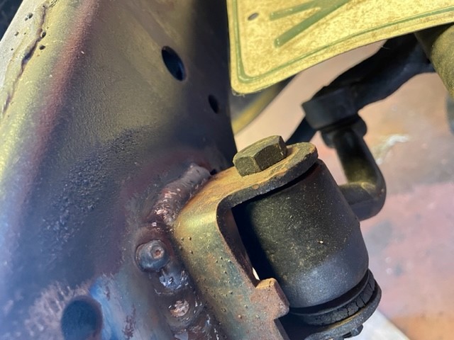 (steering3.jpg) (steering3.jpg)
Attachments
----------------
 steering3.jpg (74KB - 84 downloads) steering3.jpg (74KB - 84 downloads)
|
|
| |
|

Expert 5K+
Posts: 9904
       
Location: Lower Mainland BC | .
I guess the extra "ear" mounting slots might have only happened late in the model run, when there *MIGHT* have been a possibility of a cast-iron Torqueflite being installed in 56 Plymouth.
Some Plymouths had this (from a BAT referenced above)

Some apparently did not (have the extra slots) (from an eBay auction for a bare bones 56 Belvedere frame):
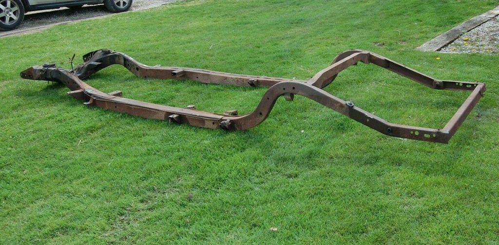 (56PlymouthBelvedereRawFrame_1_small.jpg) (56PlymouthBelvedereRawFrame_1_small.jpg)
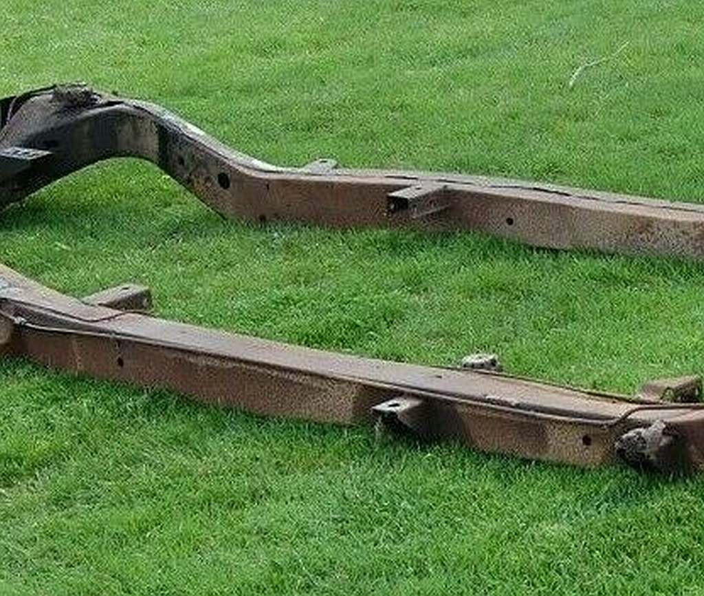 (56PlymouthBelvedereRawFrame_TransMountingEarDetail.jpg) (56PlymouthBelvedereRawFrame_TransMountingEarDetail.jpg)
Attachments
----------------
 56PlymouthBelvedereRawFrame_1_small.jpg (148KB - 64 downloads) 56PlymouthBelvedereRawFrame_1_small.jpg (148KB - 64 downloads)
 56PlymouthBelvedereRawFrame_TransMountingEarDetail.jpg (149KB - 59 downloads) 56PlymouthBelvedereRawFrame_TransMountingEarDetail.jpg (149KB - 59 downloads)
|
|
| |
|

Expert 5K+
Posts: 9904
       
Location: Lower Mainland BC | .
It is pretty much exactly four years ago since I had my 56 Dodge D500 with Powerflite converted to a D500 with A-466 cast-iron Torqueflite.
In that process, the transmission shop farmed out what they thought was the required modifications to the transmission cross-member to meet
my requirements of not touching the OE Powerflite mounting ears. This is shown/discussed above.
I was not and still am not happy with their slice and dice solution. That said, what they did/ had done has worked just fine for these past four years.
HOWEVER, I know of at least two fellows who are currently looking at an A-466 swap into a 56 Dodge/Plymouth chassis. Therefore, in hopes helping them
avoid what I experienced, I started to think about an alternative mounting system.
Based on that thought and my previous trials with a channel section and my apparent "love" of the Chevy mounts, I have come up with "Plan Z",
which I hope would be my last idea for cross member mount for a A-466 swap into a 55-56 Dodge/Plymouth Powerflite chassis.
The main part of Plan Z is the channel that I had previously found to potentially work well with the OE cross member (which as an aside, has PN 1636 819, and was
common to both the 55-56 Dodges and Plymouths).
This:

The other part of Plan Z is to use a mount that takes the weight of the cross-member and the tail of the transmission directly onto the top of the frame rail.
This was part of the OE mount (show in a previous photo from Ralf in Finland) and the Chevy transmission mounts offered by Speedway.
Ralf's chassis:

Speedway's offerings:

Similar Southwest Speed's offering showing self-tappers for the connection between the side mounts and the frame members:

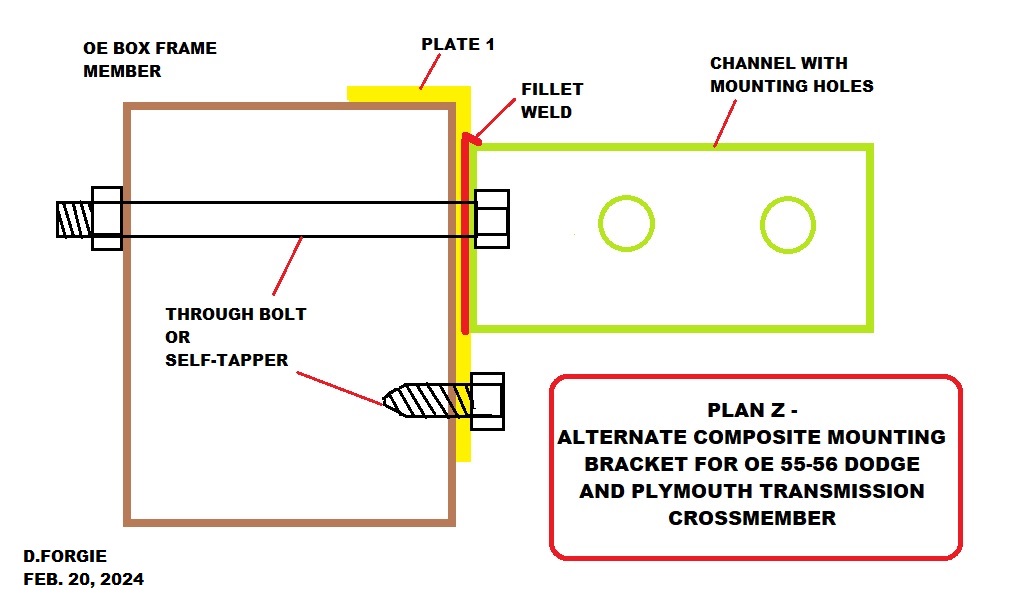
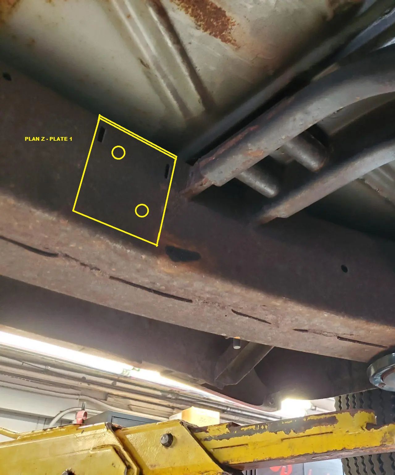
So Plan Z starts with a flat plate that is bent to have 90 deg lip that sits on top of the frame rail, with a down leg that clings to the
inner side of the frame rail. Eventual attachment of this plate, "Plate 1" would be by either through bolts or self-tappers. Welding along
the vertical edges of the channel would also be possible for those so inclined, equipped and skilled. Bolts or self-tappers through Plate 1 would
be staggered to avoid creating a significant weak point in the frame. This makes self tappers a better idea in my mind. 
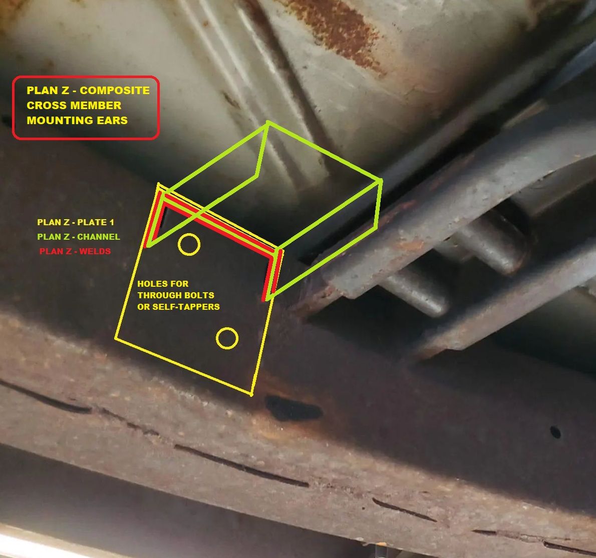
The second part of the Plan Z mount would be the channel piece as previously investigated. The channel would be drilled through for
OE style through bolts. The channel would be welded to Plate 1 once the proper height was determined. I presume that the side Plates
Plate 1-L and Plate 1-R would be roughly in place with the channel over the OE cross-member. The cross-member would be attached to
the A-466 via the OE mounting pad and the tail of the transmission held in place by a transmission jack.
Once the suitable transmission height was determined, the location of the channel on the Plates 1 would be marked and then the Plates
removed and the channels welded to the Plates (the more seam welds the better).
Not sure when the location of the holes in the channel would be determined but they would be marked and drilled.
The plates with the channels would be installed against their respective left and right frame rails and the OE cross member, attached to
the transmission would be installed into the new mounts.
PROBLEMS that would need to solved in this process:
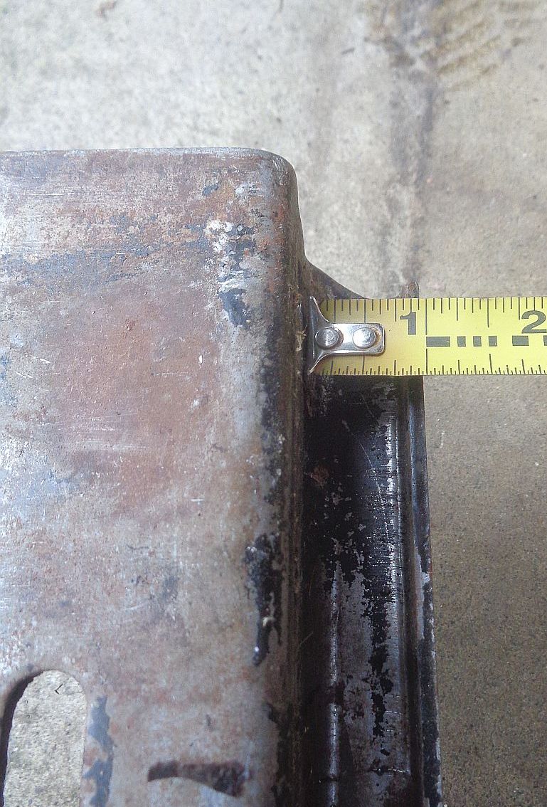
1. Based on my previous investigations, I think there is an issue with the 1" wide flange on the OE cross-member in the vicinity of the OE
mounting ears. I think that during the trial fitting of the Plan Z mounts, it will be determined that some of the OE cross-member flange will
have to be removed in order to permit the cross-member and Plan Z mounts to tuck in close to the OE mounting ears.
2. I am not sure how much clearance there is going to be for nuts on the end of the OE-style mounting bolts. It might be necessary to
weld nuts to the forward side of the channels to receive the through bolts. (???)
Just my current thoughts. 
Some diagrams, etc:
Edited by 56D500boy 2024-02-20 8:08 PM
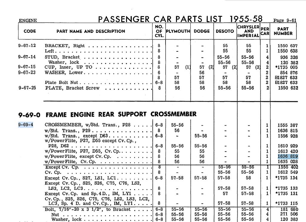 (55-56DodgePlymouthNonConvertiblePowerFliteTransCrossMember_1636819.jpg) (55-56DodgePlymouthNonConvertiblePowerFliteTransCrossMember_1636819.jpg)
 (PlanZAlternateCompositeMountingBracketForOEDodgeAndPlymouthTransmissionCrossmember.jpg) (PlanZAlternateCompositeMountingBracketForOEDodgeAndPlymouthTransmissionCrossmember.jpg)
 (56PylmouthPowerFliteCrossMember_PlanZ_Plate1.jpg) (56PylmouthPowerFliteCrossMember_PlanZ_Plate1.jpg)
 (56PylmouthPowerFliteCrossMember_PlanZ_Plate1andChannel_trimmed.jpg) (56PylmouthPowerFliteCrossMember_PlanZ_Plate1andChannel_trimmed.jpg)
 (OE56DodgePowerFliteTransmissionCrossMember_1_small.jpg) (OE56DodgePowerFliteTransmissionCrossMember_1_small.jpg)
 (OE56DodgePowerFliteTransmissionCrossMember_FlangeWidth.jpg) (OE56DodgePowerFliteTransmissionCrossMember_FlangeWidth.jpg)
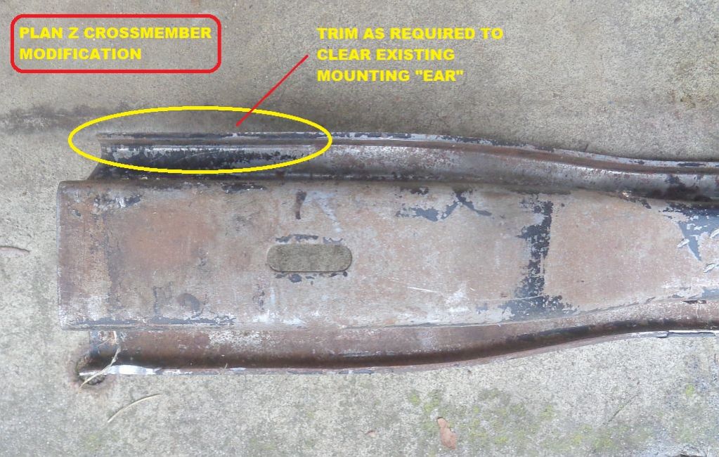 (OE56DodgePowerFliteTransmissionCrossMember_LeftEnd_PlanZtrimming.jpg) (OE56DodgePowerFliteTransmissionCrossMember_LeftEnd_PlanZtrimming.jpg)
Attachments
----------------
 55-56DodgePlymouthNonConvertiblePowerFliteTransCrossMember_1636819.jpg (163KB - 26 downloads) 55-56DodgePlymouthNonConvertiblePowerFliteTransCrossMember_1636819.jpg (163KB - 26 downloads)
 PlanZAlternateCompositeMountingBracketForOEDodgeAndPlymouthTransmissionCrossmember.jpg (101KB - 26 downloads) PlanZAlternateCompositeMountingBracketForOEDodgeAndPlymouthTransmissionCrossmember.jpg (101KB - 26 downloads)
 56PylmouthPowerFliteCrossMember_PlanZ_Plate1.jpg (176KB - 24 downloads) 56PylmouthPowerFliteCrossMember_PlanZ_Plate1.jpg (176KB - 24 downloads)
 56PylmouthPowerFliteCrossMember_PlanZ_Plate1andChannel_trimmed.jpg (128KB - 25 downloads) 56PylmouthPowerFliteCrossMember_PlanZ_Plate1andChannel_trimmed.jpg (128KB - 25 downloads)
 OE56DodgePowerFliteTransmissionCrossMember_1_small.jpg (98KB - 33 downloads) OE56DodgePowerFliteTransmissionCrossMember_1_small.jpg (98KB - 33 downloads)
 OE56DodgePowerFliteTransmissionCrossMember_FlangeWidth.jpg (191KB - 26 downloads) OE56DodgePowerFliteTransmissionCrossMember_FlangeWidth.jpg (191KB - 26 downloads)
 OE56DodgePowerFliteTransmissionCrossMember_LeftEnd_PlanZtrimming.jpg (140KB - 27 downloads) OE56DodgePowerFliteTransmissionCrossMember_LeftEnd_PlanZtrimming.jpg (140KB - 27 downloads)
|
|
| |
|
Extreme Veteran
Posts: 351
    
| Hi Dave, I understand what you are saying and agree with the idea of weight distribution and height. My idea of the frame brackets is based on your earlier part of this thread and our discussions. As I am still sitting on the beach in Mexico and I am pensile sketching ideas I have not figured out how to add photos to your thread, so.. I would fabricate, as I have most of the tools and what I don’t have I have access to, a frame bracket very similar to the existing bracket that is now welded to the frame for the Powerflite transmission crossmember support. My bracket will have a “flange” that sits on the top of the frame and welded to the frame on the vertical legs. I will leave the original bracket in place. The T/F is approx 4” longer than the P/F. From your photos the original bracket has a flange on the lower edge 1” wide. My bracket will only have a flange on the rear. This will leave me approx 3” between the old and the new for a weld. No problem to get in there. As this is all theory at time time there could be some running changes. Once I am back in my shop I will post details.
I would not use a through bolt unless I was able to have a spacer between the 2 sides of the box frame rail to keep from crushing. I’m not sure about self threading bolts in 1/8” thick metal. Possibly a Nutsert. They come in sizes up to 1/2”
Maybe the sun has baked my brain and I’m all wet.
Del S |
|
| |
|

Expert 5K+
Posts: 9904
       
Location: Lower Mainland BC | dels56 - 2024-02-20 8:00 PM
I would not use a through bolt unless I was able to have a spacer between the 2 sides of the box frame rail to keep from crushing. I’m not sure about self threading bolts in 1/8” thick metal. Possibly a Nutsert. They come in sizes up to 1/2”
Del S
Thanks Del. I had forgotten that I had said this, back in March 2019:
56D500boy - 2019-03-26 5:25 PM
Talking to my fabricator neighbour we decided that the end plates (with the new "ears" welded to the plate) could be fastened to the frame with nutserts and bolts and, if I felt the need, an inch or so of welding "stitching" added to each edge of the end plates (on both sides of the car) (to be determined).
So nutserts it is!
Regarding the OE mounting "Ear", the lower flange sits inside the OE cross-member's flange so it is only about 1/2" wide.
On that basis, it might be worthwhile considering trimming off the rearward OE ear flange as well as trimming a section of the cross-member flange so the new Plan Z mount channel could cozy right up to the OE ear, allowing long bolts to go through the Plan Z channel *AND* the OE mounting ear to a) share the load and b) make it possible to access the nut on the bolt.
Just another thought. Brain: Please stop thinking already!!

Edited by 56D500boy 2024-02-21 11:29 AM
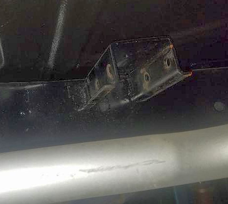 (OEPowerFliteTransmissionMountEarShowingLowerFlangeWidth.jpg) (OEPowerFliteTransmissionMountEarShowingLowerFlangeWidth.jpg)
Attachments
----------------
 OEPowerFliteTransmissionMountEarShowingLowerFlangeWidth.jpg (54KB - 21 downloads) OEPowerFliteTransmissionMountEarShowingLowerFlangeWidth.jpg (54KB - 21 downloads)
|
|
| |
|

Expert 5K+
Posts: 9904
       
Location: Lower Mainland BC | 56D500boy - 2024-02-21 7:51 AM
On that basis, it might be worthwhile considering trimming off the rearward OE ear flange as well as trimming a section of the cross-member flange so the new Plan Z mount channel could cozy right up to the OE ear, allowing long bolts to go through the Plan Z channel *AND* the OE mounting ear to a) share the load and b) make it possible to access the nut on the bolt.
Just another thought.
This a sketch of that thought. The OE ear flange gets trimmed as does part of the OE cross-member flange. The Plan Z channel and OE mountng ear are touching. The location of the mounting holes
would be marked on the Plan Z channel and then drilled. The through-bolts would probably need to be 8" or so long (they might or might not exist (??)).
Edited by 56D500boy 2024-02-21 5:54 PM
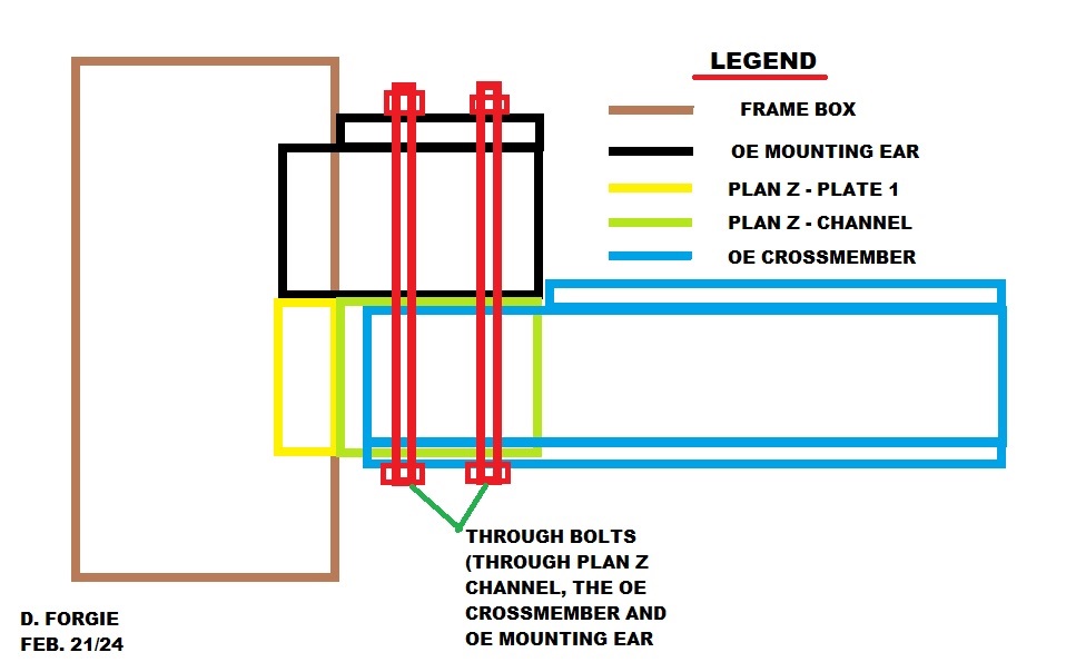 (PlanZAlternateCompositeMountingBracketForOEDodgeTransmissionCrossmember_MountingOption2.jpg) (PlanZAlternateCompositeMountingBracketForOEDodgeTransmissionCrossmember_MountingOption2.jpg)
Attachments
----------------
 PlanZAlternateCompositeMountingBracketForOEDodgeTransmissionCrossmember_MountingOption2.jpg (87KB - 27 downloads) PlanZAlternateCompositeMountingBracketForOEDodgeTransmissionCrossmember_MountingOption2.jpg (87KB - 27 downloads)
|
|
| |
|

Expert 5K+
Posts: 9904
       
Location: Lower Mainland BC | .
This is what Del S (Dels56) sent me this AM
"Dave: This is my idea of brackets to relocate the cross-member.
If one wanted to bolt this bracket to the frame rather than weld, all it would require is a plate welded in the bracket where it goes against the frame. The nutserts have a head so the plate would need to be inset the thickness of the nutsert head. Clear as mud?
Add it to the thread if you wish./ Del"
See Del's sketch below:
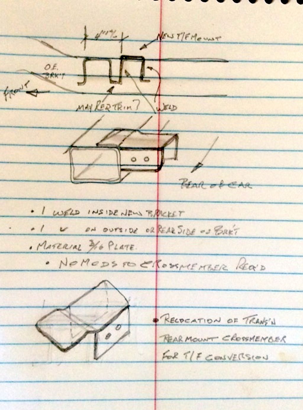 (DelSsSketchOfAnAlternativeTransMountEarForTFconversion.jpg) (DelSsSketchOfAnAlternativeTransMountEarForTFconversion.jpg)
Attachments
----------------
 DelSsSketchOfAnAlternativeTransMountEarForTFconversion.jpg (165KB - 27 downloads) DelSsSketchOfAnAlternativeTransMountEarForTFconversion.jpg (165KB - 27 downloads)
|
|
| |
|

Expert 5K+
Posts: 9904
       
Location: Lower Mainland BC | .
Del sent me a new/revised sketch of his idea:
"Slight change. (B) Showing, 1 L, 1 R. notes.
Probably running changes when I get at it but in theory this works.
If you could replace sketch 1.0 with 1.1
Thanks, Del"
Too late to edit the previous post and swap out the sketches so it has to be an new one:
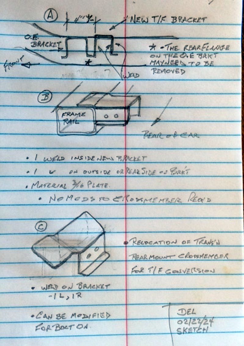 (DelSsSketchOfAnAlternativeTransMountEarForTFconversion_Feb22_24.jpg) (DelSsSketchOfAnAlternativeTransMountEarForTFconversion_Feb22_24.jpg)
Attachments
----------------
 DelSsSketchOfAnAlternativeTransMountEarForTFconversion_Feb22_24.jpg (138KB - 22 downloads) DelSsSketchOfAnAlternativeTransMountEarForTFconversion_Feb22_24.jpg (138KB - 22 downloads)
|
|
| |
|

Expert 5K+
Posts: 9904
       
Location: Lower Mainland BC | .
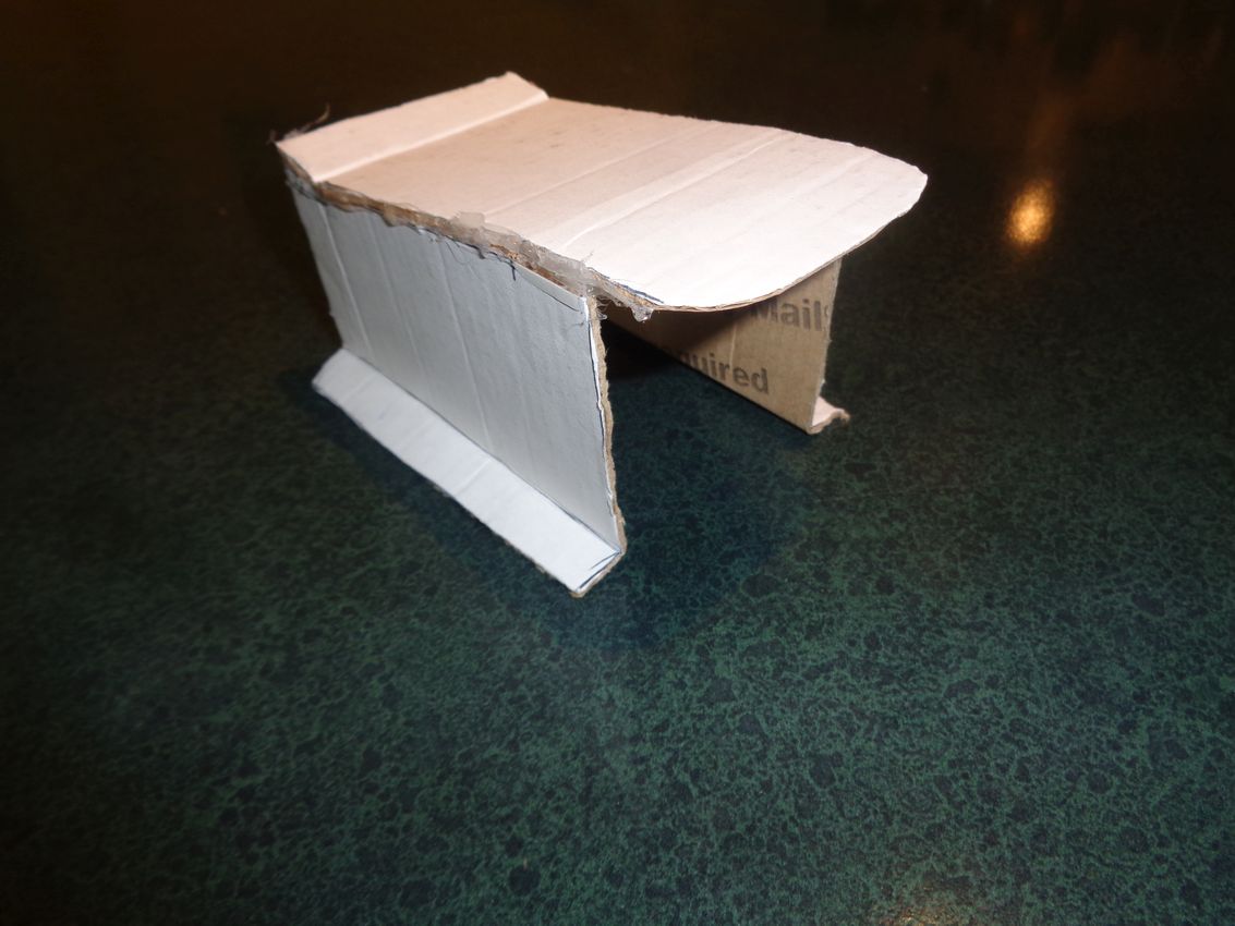
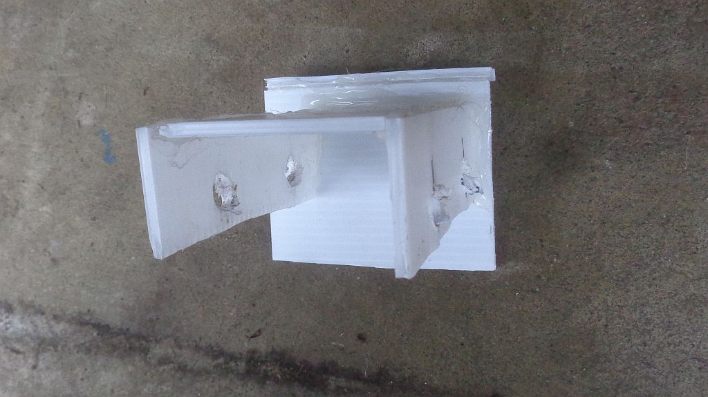
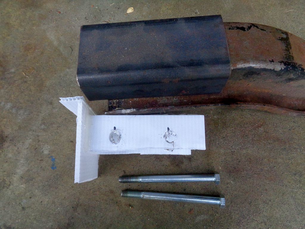
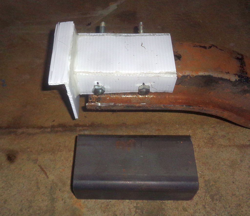
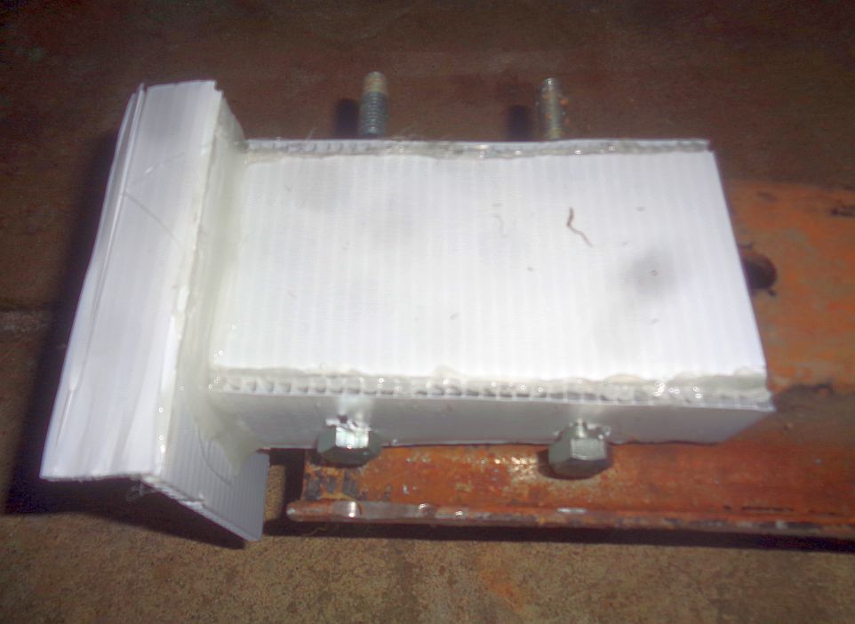
Amazing what 20 minutes, a sheet of CoroPlast, scissors and a hot glue gun can do to confirm a concept that was only on paper - until just now. 
See below:
The top flange of "Plate 1" that would rest of the top of the frame box is about 1" but it could easily be 1.5".
The width of Plate 1 is about 4" but could be a bit wider.
The drop portion of Plate 1 is about 4.5" but could easily be 5.5".
The inner width of the CoroPlast "Channel" is about 2.5" and that works great.
The sides of the CoroPlast Channel are about 1.5" and they could easily be 1.75".
I didn't attach the channel as far "forward" as might happen in reality. I needed a little gap from the edge of Plate 1 for the hot glue.
The drop of the Channel down from the top of Plate 1 is about 0.75". In reality that would have to be determined with the transmission mounted on the
cross-member and the cross-member supported with a jack and Plate 1 resting of the frame. Once the drop was determined, the Channel could be tack-welded
to Plate 1 and then Plate 1 and the Channel removed and properly welded on a welding table.
Just my thoughts. 
Edited by 56D500boy 2024-02-23 9:21 PM
 (PlanZProofOfConcept_Loose.jpg) (PlanZProofOfConcept_Loose.jpg)
 (PlanZProofOfConceptWithThroughBoltsAndSteelChannel_Loose.jpg) (PlanZProofOfConceptWithThroughBoltsAndSteelChannel_Loose.jpg)
 (PlanZProofOfConceptWithThroughBoltsAndSteelChannel.jpg) (PlanZProofOfConceptWithThroughBoltsAndSteelChannel.jpg)
 (PlanZProofOfConceptWithThroughBolts.jpg) (PlanZProofOfConceptWithThroughBolts.jpg)
Attachments
----------------
 PlanZProofOfConcept_Loose.jpg (85KB - 28 downloads) PlanZProofOfConcept_Loose.jpg (85KB - 28 downloads)
 PlanZProofOfConceptWithThroughBoltsAndSteelChannel_Loose.jpg (130KB - 25 downloads) PlanZProofOfConceptWithThroughBoltsAndSteelChannel_Loose.jpg (130KB - 25 downloads)
 PlanZProofOfConceptWithThroughBoltsAndSteelChannel.jpg (110KB - 36 downloads) PlanZProofOfConceptWithThroughBoltsAndSteelChannel.jpg (110KB - 36 downloads)
 PlanZProofOfConceptWithThroughBolts.jpg (60KB - 25 downloads) PlanZProofOfConceptWithThroughBolts.jpg (60KB - 25 downloads)
|
|
| |
|

Expert 5K+
Posts: 9672
      
Location: So. Cal | The problem with that design is that it's hard to do anything at the top of your frame. So you can bolt or weld it to the frame at the side flange. But if you do, then why have the top flange? It ends up serving no purpose. |
|
| |
|

Expert 5K+
Posts: 9904
       
Location: Lower Mainland BC | Powerflite - 2024-02-23 8:51 PM
The problem with that design is that it's hard to do anything at the top of your frame. So you can bolt or weld it to the frame at the side flange. But if you do, then why have the top flange? It ends up serving no purpose.
The purpose of that top flange on "Plate 1" is to take most of the load from the cross-member directly onto the top of the frame, thereby decreasing the amount of load that must be taken in shear by any bolts into the frame or welds along the side of the channel or plate. There was never any intent to weld or bolt that top flange to the top of the frame box. It just sits there, tight to the frame, helping to hold the weight.
If the plate ("Plate 1") is set up to be bolted to the frame on its vertical secton, it would permit more versatile, removable, mounting.
It is just an idea that I wish I had come up with 4 years ago that would have saved me some big(ish) coin. 

Edited by 56D500boy 2024-02-24 12:48 PM
|
|
| |
|

Expert 5K+
Posts: 9904
       
Location: Lower Mainland BC | .
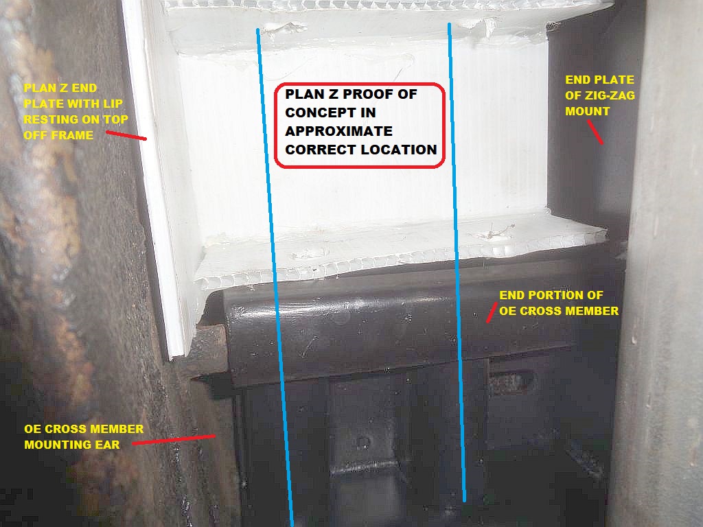
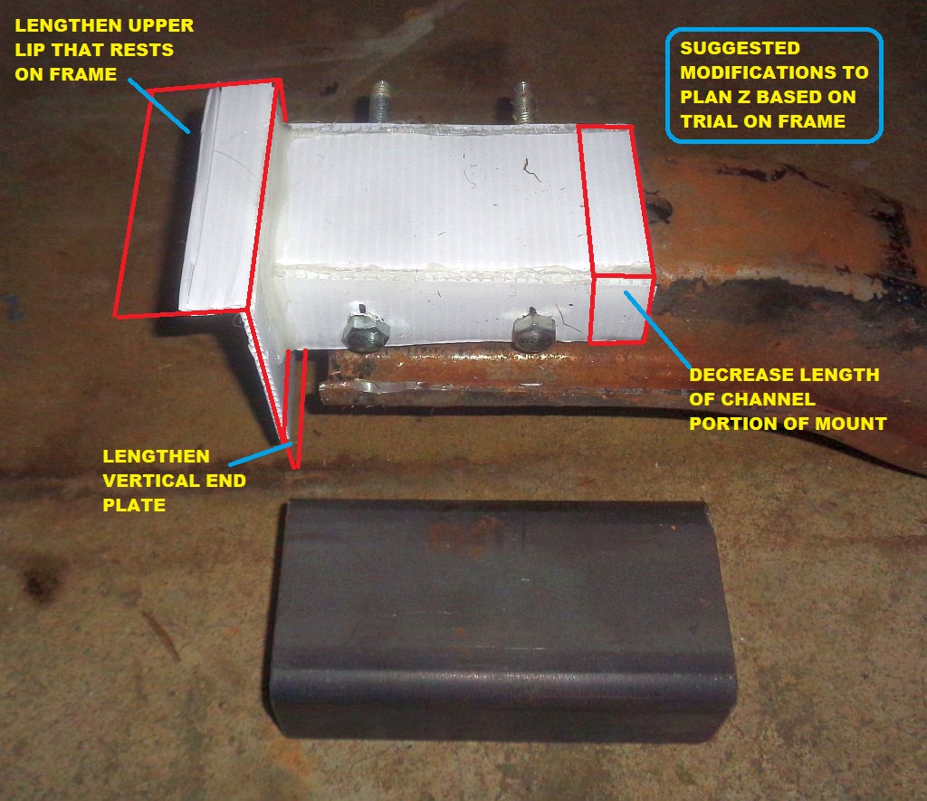
Yesterday, I had the opportunity (I dropped something and I could not retrieve it without jacking the car up (on the driver's side frame - with safety jackstand) to trial the Plan Z "proof of concept" mock-up mount
on the car.
Turns out my "eyeballing" wasn't too far off.
The top lip of the end plate of the Plan Z mount could be wider (spread the load) and the channel could be a bit shorter. The vertical portion of the end plate could be a bit
longer which would give more possibilities for nut-serts and bolts.
Two photos:
 (PlanZProofOfConceptInPlaceBesideOEMountEnd_Annotated.jpg) (PlanZProofOfConceptInPlaceBesideOEMountEnd_Annotated.jpg)
 (PlanZProofOfConceptWithThroughBoltsAndSteelChannel_Changes.jpg) (PlanZProofOfConceptWithThroughBoltsAndSteelChannel_Changes.jpg)
Attachments
----------------
 PlanZProofOfConceptInPlaceBesideOEMountEnd_Annotated.jpg (174KB - 16 downloads) PlanZProofOfConceptInPlaceBesideOEMountEnd_Annotated.jpg (174KB - 16 downloads)
 PlanZProofOfConceptWithThroughBoltsAndSteelChannel_Changes.jpg (236KB - 20 downloads) PlanZProofOfConceptWithThroughBoltsAndSteelChannel_Changes.jpg (236KB - 20 downloads)
|
|
| |
 Seeking Photos of the rear engine/transmission cross-member mounting ears
 Seeking Photos of the rear engine/transmission cross-member mounting ears