| The Forward Look Network | ||
| ||
 "Make-Up" your Car! "Make-Up" your Car!Jump to page : < 1 2 3 4 5 6 7 > Now viewing page 5 [50 messages per page] | View previous thread :: View next thread |
| Forward Look Technical Discussions -> Body, Glass, Interior and Trim | Message format |
| sermey |
| ||
Expert Posts: 1208   Location: SWITZERLAND |
Car Production Broadcast: My restored Car Production Broadcast I had already presented a time ago in the appropriate forum. In this thread here I just show HOW I did it, not must be the best way to go – but it works.
Scan the sheet with 1200dpi in precise vertical/horizontal orientation with Photoshop. It needs Win7 64-bit with at least 8MB RAM. The original scan is in the first layer named background (01). The layer 00 is a copy of the background in case of a disaster. . . . (01).
Create the next layers 01 – 06 for individual mastering, and freeze them from moving (02). The layer 01 is the background pattern of the sheet, sample taken in a clean segment in layer 00. Remember, this background in not a uniform color, thus a pattern! Next copy the selected items from layer 00 into the designated layers as shown in (02), ready there for clean and restore individually. If the result in a layer is not satisfactory, then just delete and re-copy it.
Examples of restored layers: Layer 02: Original Text with Grid brown (03). Layer 03: Original Typed Numbers black (04).
The typed numbers are not upgraded as they could be in order to keep their authentification. When all layers have been restored, merge all in one layer to stay fixed. This will be the final Car Production Broadcast Restored, saved here in a smaller resolution, as JPG-Picture (05), or 1 : 1 as PDF-File with 144dpi (because of the 250k limitation) (08).
The letters and the grid can as well be reproduced instead restored. Here the letters then are taken from the font library (Arial, Bold, Smooth, Color RGB: 207-113-46) and the lines are created by construction, all in Photoshop. In direct comparison to the original in the left, the difference is hardly visible (06). The Original Typed Numbers remains as before (04). Each single number can be selected, copied and inserted individually for another specific sheet (07).
Now, any missing Car Production Broadcast can be re-created by anyone. Happy printing! - SERGE -
(01 Car Production Broadcast Scanned in.jpg) (02 Layers Listing.jpg) (03 Original Text with Grid.jpg) (04 Original Typed Numbers black.jpg) (05 Car Production Broadcast Restored.jpg) (06 Comparison Original Text - New Font.jpg) (07 Car Production Broadcast New Texted.jpg) Attachments ----------------  01 Car Production Broadcast Scanned in.jpg (123KB - 754 downloads) 02 Layers Listing.jpg (118KB - 682 downloads) 03 Original Text with Grid.jpg (119KB - 710 downloads) 04 Original Typed Numbers black.jpg (40KB - 679 downloads) 05 Car Production Broadcast Restored.jpg (132KB - 718 downloads) 06 Comparison Original Text - New Font.jpg (122KB - 699 downloads) 07 Car Production Broadcast New Texted.jpg (137KB - 707 downloads) 08 Car Production Broadcast Restored 144dpi.pdf (120KB - 737 downloads) 01 Car Production Broadcast Scanned in.jpg (123KB - 754 downloads) 02 Layers Listing.jpg (118KB - 682 downloads) 03 Original Text with Grid.jpg (119KB - 710 downloads) 04 Original Typed Numbers black.jpg (40KB - 679 downloads) 05 Car Production Broadcast Restored.jpg (132KB - 718 downloads) 06 Comparison Original Text - New Font.jpg (122KB - 699 downloads) 07 Car Production Broadcast New Texted.jpg (137KB - 707 downloads) 08 Car Production Broadcast Restored 144dpi.pdf (120KB - 737 downloads) | ||
| |||
| ToMopar |
| ||
Elite Veteran Posts: 1159  Location: D-70199 Heslach | Serge, It's great to "restore" all the history what comes with the car. Great work! | ||
| |||
| d500neil |
| ||
Exner Expert 19,174 posts. Neil passed away 18 Sep 2015. You will be missed, Neil! Posts: 19146   Location: bishop, ca | PM sent (very-soon!) | ||
| |||
| sermey |
| ||
Expert Posts: 1208 Location: SWITZERLAND | License Plate Lamp: For a brighter light the bulb can as well be replaced by a LED. The lamp unit is fixed with a bracket (01) (02). The heat of the bulb, consuming 5W, causes the lens to melt partially (03). As replacement I used the same LED as for the dome lights. The contacts here are brigded for a full power (04). The fixing pins on the LED can be left as is. Just bent out the tab, on the concerned side of the lamp socket, for turning the LED in, view one side and the other side (05). Now the license plate shines brighter at lower power consumption, and without melting the lens anymore (06). - SERGE - Edited by sermey 2015-05-20 6:15 AM (01 Lamp Unit.jpg) (02 Lamp Unit Rear View.jpg) (03 Melted Lens.jpg) (04 Bulb 5W - LED.jpg) (05 Lamp Socket Bent.jpg) (06 Bright License Plate.jpg) Attachments ---------------- 01 Lamp Unit.jpg (72KB - 708 downloads) 02 Lamp Unit Rear View.jpg (84KB - 676 downloads) 03 Melted Lens.jpg (71KB - 717 downloads) 04 Bulb 5W - LED.jpg (88KB - 669 downloads) 05 Lamp Socket Bent.jpg (80KB - 673 downloads) 06 Bright License Plate.jpg (100KB - 664 downloads) | ||
| |||
| di_ch_NY56 |
| ||
Expert Posts: 1530  Location: ZH, Switzerland | Hell! It looks wonderful. Thank you very much Serge. Did you know, there are LED lamps available with a BA15d socket with to connection points?
Kind regards,
Dieter Edited by di_ch_NY56 2015-05-20 6:08 AM | ||
| |||
| sermey |
| ||
Expert Posts: 1208 Location: SWITZERLAND | . . . Did you know, there are LED lamps available with a BA15d socket with to connection points? . . . Yes Dieter, but I wanted the brightest light by using a "STOP"- LED that fits in the lamp unit. - SERGE - Edited by sermey 2015-05-20 3:14 PM | ||
| |||
| 57plybel |
| ||
Extreme Veteran Posts: 594 Location: Melbourne, Australia | Love this thread, Sermey; beautiful work on a perfect restoration IMHO.... great idea with the low fuel warning and the thermoplastic work. It would take me a lifetime to reach this standard of restoration...
There is a fuel pump relay which has a trigger from the distributor I believe. It senses revs above cranking speed and only supplies power in this senario... upon stalling ( zero revs) power and thus fuel pump are inoperative..,.
Colin | ||
| |||
| jimntempe |
| ||
Expert Posts: 2312 Location: Arizona | Some fuel pump relays get their power thru an oil pressure switch. So when the revs drop to zero and oil pressure also drops to zero the fuel pump power is shut off. | ||
| |||
| sermey |
| ||
Expert Posts: 1208 Location: SWITZERLAND |
Glove Box Compartment: A Crypton bulb type produces a whiter light but consumes some more power (01). As LED replacement I selected the long type (02). The diffusion of the light is circular, as needed for this application (03).
Just swap the devices? No, the socket of the bulb with integrated switch has reversed polarity (04). The (+) of the bulb will be grounded, at reversed voltage the LED cannot work.
In order to keep this socket as original, there was no other way then to interchange the LED connections, as already shown. De-solder the connection and the lamp socket can be removed, for it is just pushed on the plastic base (05). That’s why I had some problems to mount the LED, I turned the LED-Unit whereas the lamp socket didn’t.
Then reverse the polarity in the LED and extend the wire (06), push on the lamp socket, solder and glue it (07). Done.
As my built-in radio covers partly the illumination, I added a LED-Array (08) in parallel to the replacement LED. It is supplied by two wires, the red wire is soldered on a (+12V) pad in front of the unit, the blue wire (GRD) now on the lamp socket (09). Then again: Push on the lamp socket, solder and glue it (10).
Checking the set at reduced voltage (for picture), both lamps work together as one unit (11) and is ready for mount.
Backside the LED-Array there is an adhesive surface for easy fixing, here on bottom of the radio.
Except the side walls, I have covered the box inside with a black carpet inlay, a rest of my cars carpet (12).
Then the right edge of the glove box has become damaged in friction with the metal door arm (13). For protection I inserted a plastic profile as used to fix paper sheets (13). This edge now is protected from further stress with the door arm (14).
Finally, the glove box compartment shows an evenly spread illumination and the interior looks nice (15). – SERGE -
(01 Glove Box Bulb.jpg) (02 Bulb and replacement LEDs.jpg) (03 Long LED ON.jpg) (04 Lamp Socket with Switch.jpg) (05 LED Socket removed.jpg) (06 LED Polarity reversed.jpg) (07 LED Socket pushed on - soldered - glued.jpg) (08 LED Array 12V.jpg) (09 Plus on LED Socket.jpg) (10 Fixing the LED Socket.jpg) (11 Checking the Set.jpg) (12 Black Carpet Overlay.jpg) (13 Right Box Edge Damaged.jpg) (14 Plastic Profile.jpg) (15 Exposed Edge Protected.jpg) (16 Final Glove Box Compartment.jpg) Attachments ---------------- 01 Glove Box Bulb.jpg (96KB - 680 downloads) 02 Bulb and replacement LEDs.jpg (69KB - 676 downloads) 03 Long LED ON.jpg (64KB - 694 downloads) 04 Lamp Socket with Switch.jpg (43KB - 699 downloads) 05 LED Socket removed.jpg (96KB - 664 downloads) 06 LED Polarity reversed.jpg (82KB - 691 downloads) 07 LED Socket pushed on - soldered - glued.jpg (88KB - 684 downloads) 08 LED Array 12V.jpg (81KB - 695 downloads) 09 Plus on LED Socket.jpg (82KB - 701 downloads) 10 Fixing the LED Socket.jpg (77KB - 672 downloads) 11 Checking the Set.jpg (64KB - 681 downloads) 12 Black Carpet Overlay.jpg (66KB - 665 downloads) 13 Right Box Edge Damaged.jpg (104KB - 666 downloads) 14 Plastic Profile.jpg (57KB - 723 downloads) 15 Exposed Edge Protected.jpg (94KB - 673 downloads) 16 Final Glove Box Compartment.jpg (93KB - 701 downloads) | ||
| |||
| jimntempe |
| ||
Expert Posts: 2312 Location: Arizona | Speaking of LEDs, My turn signal lenses have darkened with time to the point where you can't even tell when the signals are on during the day. I did some checking and the #57 indicator bulbs put out about 3 candlepower. I found some replacement green LEDs that put out about 9 cp at www.superbrightleds.com . I put them in for the turn signal indicators and a red LED for the high beams and now I can see my indicator lights in daylight!!! Photos in my album http://www.forwardlook.net/forums/photos/photo-thumbnails.asp?album... | ||
| |||
| ToMopar |
| ||
Elite Veteran Posts: 1159 Location: D-70199 Heslach | Serge, your car was pictured by a friend (2015-Schweiz_Uster-041x.jpg) Attachments ---------------- 2015-Schweiz_Uster-041x.jpg (191KB - 642 downloads) | ||
| |||
| sermey |
| ||
Expert Posts: 1208 Location: SWITZERLAND | Thank you for posting, Tom. It was a very hot day, therefore my car with top up - and some people topless! - SERGE - | ||
| |||
| sermey |
| ||
Expert Posts: 1208 Location: SWITZERLAND | Cable for Set the Time: The time of the electric clock on the 59 DODGE is being set by a separate control knob mounted under the dashboard (01). The original time setting cable at 30cm length is too short for remove the instruments unit without disconnect it (02). Not only, the white vinyl shell has become stiff due to age and thus, any used replacement I purchased, was broken on the clockside end. I found a replacement Scooter Speedometer Cable (04), with similar coupling to the clock (05). This new coupler including the core, original 3.2mm – new 3.0mm, could be used as is with small modifications (06). Just extend the gap and reduce the length as the sample (07). This highly flexible metal shelI must be cut on both sides to the new length by grinding (08). When heating the connectors, the vinyl shell of the old cable can be removed easily on both sides (09)(10). As soldered the connection will never come out again: Tin first the junction surfaces of both parts (11). Then when heated push the shell into the connector, it just fits (12). Because the old core couldn’t be removed from the control axis, the pressed part had to be grinded around. Deepen the so shortened hole of the control axis (3,2mm) by 8mm. The control axis and the new core are glued with a strong Cyanolit, always respecting the original working distances. Don't forget to insert the spring before! A fine tuning of the functionality can be done by heating the soldered connector and moving it, in order to extend or reduce the length up to 1mm, this on both sides of the control cable (13).
Now, the new remote cable for set the time is ready to mount, works as the original one, but is much longer, with a steel shell and again flexible (14). – SERGE - Edited by sermey 2015-09-12 10:57 AM (01 Clock Time Setting Knob.jpg) (02 Original Time Setting Cable.jpg) (03 Label Scooter Speedometer Cable.jpg) (04 Connections Scooter Speedometer Cable.jpg) (05 Clockside Coupler.jpg) (06 Comparison Couplers Clockside.jpg) (07 Modifying Gap and Length of new Coupler.jpg) (08 Cutting both sides to the new Length.jpg) (09 Remove the Vinyl Tube by Heating.jpg) (10 Removed Broken Vinyl Tube.jpg) (11 Tinned Connector ready for Solder.jpg) (12 Soldered Connector.jpg) (13 Assembled Time Setting Cable.jpg) (14 Old and New Time Setting Cable.jpg) Attachments ---------------- 01 Clock Time Setting Knob.jpg (118KB - 719 downloads) 02 Original Time Setting Cable.jpg (31KB - 686 downloads) 03 Label Scooter Speedometer Cable.jpg (114KB - 654 downloads) 04 Connections Scooter Speedometer Cable.jpg (43KB - 677 downloads) 05 Clockside Coupler.jpg (48KB - 694 downloads) 06 Comparison Couplers Clockside.jpg (77KB - 663 downloads) 07 Modifying Gap and Length of new Coupler.jpg (85KB - 701 downloads) 08 Cutting both sides to the new Length.jpg (70KB - 676 downloads) 09 Remove the Vinyl Tube by Heating.jpg (71KB - 651 downloads) 10 Removed Broken Vinyl Tube.jpg (58KB - 661 downloads) 11 Tinned Connector ready for Solder.jpg (56KB - 695 downloads) 12 Soldered Connector.jpg (55KB - 682 downloads) 13 Assembled Time Setting Cable.jpg (79KB - 657 downloads) 14 Old and New Time Setting Cable.jpg (55KB - 684 downloads) | ||
| |||
| wizard |
| ||
Board Moderator & Exner Expert 10K+ Posts: 13049 Location: Southern Sweden - Sturkö island | It's nice to see the final result as you informed me about that you worked on this project Serge! Another "sergerized" improvement, thanks' for sharing this smart solution! | ||
| |||
| ToMopar |
| ||
Elite Veteran Posts: 1159 Location: D-70199 Heslach | 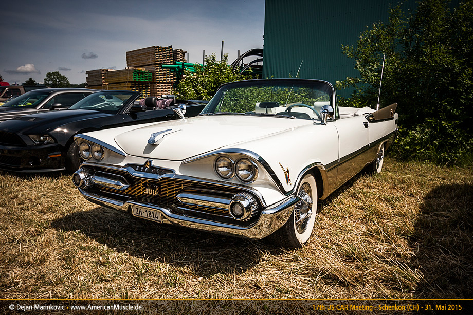 | ||
| |||
| sermey |
| ||
Expert Posts: 1208 Location: SWITZERLAND | Air-Deflector: The Air-Deflector under the dashboard distributes the incoming air from the center inlet to the left and right passenger side. It is made with a 1.5mm cardboard, therefore very sensitive to deformation, especially exposed when removing the radio. In my car this item was already badly damaged, and here out of function (01). Fixed with three screws it can easy be removed. From this a flat template could be reconstructed (02), and then modeled in 3D-CAD (03, 04). As material the backboard of a A4-scratchpad can be used, I found a thickness of 1.3mm that could simply be cut with a scissor (05). For a straight, edged ply use a bench vice, each side separate (05a). Painting in black to fit the surrounding and increasing the stiffness as well, after a distance check (100mm) the new Air-Deflector was ready to be mounted (06). Now the incoming air is redirected, as it should - another small and simple restoration (07). - SERGE -
N.B. I didn’t removed the Air-Deflector when mounting back the Radio – first signs of “contacts” can already be seen! The Template in PDF, A4, 1:1, ready for direct print-out, is added (08).
Edited by sermey 2016-02-19 10:14 PM (01 Air-Deflector Damaged.jpg) (02 Template Air Deflector Flat.jpg) (03 Air Deflector FrontView CAD.jpg) (04 Air Deflector SideView CAD.jpg) (05 Cut and Bent.jpg) (05a Plying the Cardboard.jpg) (06 Painted and Verifying Distance.jpg) (07 New Air-Deflector Mounted.jpg) Attachments ---------------- 01 Air-Deflector Damaged.jpg (69KB - 623 downloads) 02 Template Air Deflector Flat.jpg (53KB - 639 downloads) 03 Air Deflector FrontView CAD.jpg (76KB - 623 downloads) 04 Air Deflector SideView CAD.jpg (113KB - 612 downloads) 05 Cut and Bent.jpg (94KB - 625 downloads) 05a Plying the Cardboard.jpg (83KB - 617 downloads) 06 Painted and Verifying Distance.jpg (94KB - 626 downloads) 07 New Air-Deflector Mounted.jpg (164KB - 626 downloads) 08 Template Air-Deflector A4-300dpi.pdf (78KB - 627 downloads) | ||
| |||
| sermey |
| ||
Expert Posts: 1208 Location: SWITZERLAND | Speedometer 1: In the 1959 Dodge “the bar-type safety speedometer indicates green to 30 m.p.h., amber from 30 to 50 m.p.h., and red above 50 m.p.h.(Ross Roy)”. There are two different speedometer types, A and B. The second B has the additional option “speed warning signal” (01). Visually the two speedometers differ in various aspects as shown in direct comparison: Front Panel (02), Rear Panel (03), View Right Side (04), Different Covers (05) and Different Spring Systems (06). Due to the additional mechanics of the speed warning system, the drums (axes) and the glasses are not the same. Important to know is that the speed scales and the color bars on the drum are identical for both types (07). Pictures from my spare parts. (will be continued) - SERGE - Edited by sermey 2016-02-23 5:54 PM (01 Speed Warning Signal (Ross Roy).jpg) (02 Front Panel.jpg) (03 Rear Panel.jpg) (04 View Right Side.jpg) (05 Different Covers.jpg) (06 Different Spring Systems.jpg) (07 View Inside - Identical Color Bars.jpg) Attachments ---------------- 01 Speed Warning Signal (Ross Roy).jpg (110KB - 611 downloads) 02 Front Panel.jpg (87KB - 639 downloads) 03 Rear Panel.jpg (69KB - 664 downloads) 04 View Right Side.jpg (82KB - 619 downloads) 05 Different Covers.jpg (76KB - 641 downloads) 06 Different Spring Systems.jpg (87KB - 608 downloads) 07 View Inside - Identical Color Bars.jpg (110KB - 652 downloads) | ||
| |||
| sermey |
| ||
Expert Posts: 1208 Location: SWITZERLAND | Speedometer 2: With age, humidity and light, the bar colors on the drum fade out and loose visibility – NOS replacement drums are very hard to find, when found it is mostly not the one you need (01). Easiest is to apply a new speedometer decal (02), preferable in thin resistive plastic. As the drum endings may vary, the decal must be aligned to the right side, and if needed cut on the left side (03). When the scale fits exactly to the original, no additional calibration is needed. Simply check with a BW Copy (04). In a CAD simulation the steps are illustrated (05) (06) (07), and the final result shown in (08) (09). A printable PDF-File is added , A4, 1 : 1, correct decal size 234.2 x 119mm (10). The colors may vary insignificantly depending of the used printer type. Verify the printed colors with the original and correct if needed. Now a new speedometer scale without disassembling and/or replacing the drum. - SERGE -
Notice: Many printer reduce the size marginally, even when set at 100%. My A4 "BROTHER" has to be set at 100.5% to get print-out the exact width of 234.2mm (to be verified!).
Edited by sermey 2016-02-26 8:54 PM (01 NOS Auto-lite Drum.jpg) (02 1959 Dodge Speedometer Decal..jpg) (03 Drum Ends Comparison.jpg) (04 Accuracy Check.jpg) (05 Decal Ready CAD.jpg) (06 Pre-Position Decal CAD.jpg) (07 Final Position Check CAD.jpg) (08 Applied Decal Front Side CAD.jpg) (09 Applied Decal Rear Side CAD.jpg) Attachments ---------------- 01 NOS Auto-lite Drum.jpg (125KB - 619 downloads) 02 1959 Dodge Speedometer Decal..jpg (105KB - 621 downloads) 03 Drum Ends Comparison.jpg (124KB - 650 downloads) 04 Accuracy Check.jpg (104KB - 619 downloads) 05 Decal Ready CAD.jpg (99KB - 620 downloads) 06 Pre-Position Decal CAD.jpg (98KB - 652 downloads) 07 Final Position Check CAD.jpg (101KB - 614 downloads) 08 Applied Decal Front Side CAD.jpg (67KB - 596 downloads) 09 Applied Decal Rear Side CAD.jpg (63KB - 619 downloads) 10 1959 Dodge Speedometer Decal A4.pdf (77KB - 618 downloads) | ||
| |||
| sermey |
| ||
Expert Posts: 1208 Location: SWITZERLAND | Speedometer 3: The speedometer bar should show zero when the car is not moving, then it is adjusted correctly. When the green bar already shows an amount then the speedometer is mismatched as shown with the original drum (01), and similar with the new decal (02). Not showing any green at all, there is probably an under setting (03). The fine adjustment is done by removing the right cover, and shifting carefully the spring system with a pointy tool (04). For a secure and correct setting the initial green bar should preferably just be visible (05). Now the speedometer shows as it was the first day - SERGE -
Edited by sermey 2016-02-27 10:28 AM (01 Original Speedometer - Mismatched.jpg) (02 New Speedometer - Mismatched.jpg) (03 New Speedometer - Zero Minus.jpg) (04 Zero Adjustment.jpg) (05 New Speedometer - Zero Correct Setting.jpg) Attachments ---------------- 01 Original Speedometer - Mismatched.jpg (102KB - 607 downloads) 02 New Speedometer - Mismatched.jpg (99KB - 671 downloads) 03 New Speedometer - Zero Minus.jpg (98KB - 621 downloads) 04 Zero Adjustment.jpg (84KB - 620 downloads) 05 New Speedometer - Zero Correct Setting.jpg (98KB - 614 downloads) | ||
| |||
| catman |
| ||
Elite Veteran Posts: 781 Location: Montreal, Canada | Wow!!! Thanks for the PDF. Great work as usual.  | ||
| |||
| Lancer Mike |
| ||
Location: The Mile High City | Amazing and so detailed! Great work, Serge! | ||
| |||
| sermey |
| ||
Expert Posts: 1208 Location: SWITZERLAND | MOPAR Radio 856-857 with Audio Input: Even if the old Mopar Radio works perfectly, today this device is going to make no sense when the radio stations disappear, except as an eye-catcher in the car. There are high-tech conversions offered for FM-reception. These people do a nice job, as the radio keeps its full mechanical functionality. Meanwhile the DAB - Technology (Digital Audio Broadcast) is on the way and will soon replace the analog broadcasting systems (ABS), so as these modifications one day will become as well obsolete. To give the radio a “voice”, regardless of the source, an Audio Input is suggested. The original loudspeaker had already been replaced by a high power, wide-band type (01). The big high efficient magnet was grinded for just not touch the housing of the radio (02). It was obvious to have this loudspeaker driven by a power amplifier for lower impedance, and producing a higher output than the radio. I found a suitable Power Amplifier, direct operating up to 16VDC (03), with a cinch audio connection (04), that could be used for an Audio Input. From the cleaned schematic of the Mopar Radio 856,857 (05), here the resized section of the volume control unit (06). The Audio Input is done by “injecting” the sound source from earphone output of an external device (portable Radio, Cassette or CD-Player, SmartPhone), directly to the high end of the volume control A in red (07). This way the volume and the tone control of the radio is still remaining active, and the receiver operate as well. As the radio has a high impedance circuit, the audio input is decoupled by a serial resistor, minimum value 120k. The higher the value, the higher will be the attenuation of the applied input signal, but as well the lower the loading of the radio circuit. This adjustable Audio Input signal comes directly from the trimmer in the PowerAmp. The output B shown in green, comes from the tapper of the Volume Control, and leads with another 120k directly to the input of the PowerAmp. Means the inner connection of the input trimmer to the PowerCircuit has been previously cut. Note: To avoid possible hum, the two resistors 120k have to be soldered directly to the the volume control in the radio. These two wires, leading to the PowerAmp-In, are separately shielded. The 12V supply comes switched from the Radio, ground from the VC. The PowerAmp Unit has become a satellite of the radio (08). It is fixed inside the air deflector for direct access to the cinch input connector, and for easy adjustment of the audio sensitivity by the pre-set trimmer (09).While listening from audio input, the receiver is set to the end of the scale for no reception at all. Removing this system? Just cut all external cables and the radio will remain as it was before! But not forget to switch over the loudspeaker. Now the original car radio, together with the new built-in loudspeaker and a HiFi source, sounds even better as in the good old times. - SERGE -
N.B. Separate the schematics in PDF.
Edited by sermey 2016-03-18 10:16 AM (01 MOPAR Radio 856-857.jpg) (02 Grinded Loudspeaker Magnet.jpg) (03 KEMO Amplifier 12W M032S 25.jpg) (04 PowerAmp Unit.jpg) (05 Schematic Radio Mopar 856-857.jpg) (06 Schematic Resized Section VC Unit.jpg) (07 Section VC with Audio Input A-Output B.jpg) (08 MOPAR Radio with PowerAmp Unit.jpg) (09 View Mounted PowerAmp.jpg) Attachments ---------------- 01 MOPAR Radio 856-857.jpg (82KB - 602 downloads) 02 Grinded Loudspeaker Magnet.jpg (90KB - 601 downloads) 03 KEMO Amplifier 12W M032S 25.jpg (74KB - 622 downloads) 04 PowerAmp Unit.jpg (79KB - 623 downloads) 05 Schematic Radio Mopar 856-857.jpg (114KB - 658 downloads) 06 Schematic Resized Section VC Unit.jpg (72KB - 623 downloads) 07 Section VC with Audio Input A-Output B.jpg (87KB - 624 downloads) 08 MOPAR Radio with PowerAmp Unit.jpg (112KB - 671 downloads) 09 View Mounted PowerAmp.jpg (90KB - 626 downloads) Schematic Radio Mopar 856-857.pdf (197KB - 619 downloads) Schematic Radio Mopar Section Volume Control.pdf (103KB - 628 downloads) Schematic Radio Mopar VC Input A-Output B.pdf (107KB - 613 downloads) | ||
| |||
| sermey |
| ||
Expert Posts: 1208 Location: SWITZERLAND |
Horn Ring Pad 1: Years ago I purchased at the Big Meet in Vaesteras a NOS Steering Horn Ring without Pad (01). Back then I didn’t know that there are two different horn rings. The other one with pad and small golden knight (02) have been available in pad colors correspondingly to the car interior (03) (04) (05).
These pads deforms and shrinks with time and are extreme rarely to find. From the used horn ring I purchased once, I could just use the small golden knight, temporarily mounted on the ashtray of my convertible.
Recently I found a never used, NOS Horn Ring with green pad (06). All was perfect, except the pad was shrinked till 10mm at the end (07), partially deformed, the foam mostly rotted, and the metal insert widely detached due to long storage (08). The pad metal inserts, usually rusty and broken, could be cleaned (09) and inserted on the horn ring (10). By removed pad (11), the fixing gaps in the ring becomes visible (12).
In case of needed replacement I have modeled this part on CAD (13). By laser cutting the stainless sheetmetall (0.5mm) according the flat metal insert (14), and then bending it around an axis 5 – 6 mm, this item can easily be reproduced (15). By one mirror command on CAD, the opposite sheet metal is done as well (16). Attached a printable PFD-File 1:1.
The reproduction of this horn pad is firmly dedicated to the Swedish company RD Autoline (Tony), for they use the correct material as for Dash Pads, they know how to process quality foam, and fulfill a high technical standard. This here may be a contribution for a “start-up” . . . . . . - SERGE -
(to be continued)
(01 NOS Steering Horn Ring without Pad.jpg) (02 Horn Ring with Black Pad.jpg) (03 Horn Ring with Blue Pad.jpg) (04 Horn Ring with Green Pad.jpg) (05 Horn Ring with Red Pad.jpg) (06 NOS Horn Ring with Pad.jpg) (07 Shrinked Horn Pad.jpg) (08 Deformed Pad Front & Rear View.jpg) (09 Cleaned Horn Pad Metal Inserts.jpg) (10 Pad Metal inserted on Horn Ring.jpg) (11 Horn Ring Pad Removed.jpg) (12 Horn Ring Rear View.jpg) (13 Single Horn Pad Metal Insert CAD.jpg) (14 Flat Horn Pad Metal Insert CAD.jpg) (15 Flattened Metal Insert CAD.jpg) (16 Dual Horn Pad Metal Insert CAD.jpg) Attachments ---------------- 01 NOS Steering Horn Ring without Pad.jpg (82KB - 607 downloads) 02 Horn Ring with Black Pad.jpg (64KB - 613 downloads) 03 Horn Ring with Blue Pad.jpg (72KB - 613 downloads) 04 Horn Ring with Green Pad.jpg (65KB - 612 downloads) 05 Horn Ring with Red Pad.jpg (71KB - 609 downloads) 06 NOS Horn Ring with Pad.jpg (73KB - 633 downloads) 07 Shrinked Horn Pad.jpg (55KB - 607 downloads) 08 Deformed Pad Front & Rear View.jpg (79KB - 609 downloads) 09 Cleaned Horn Pad Metal Inserts.jpg (51KB - 612 downloads) 10 Pad Metal inserted on Horn Ring.jpg (73KB - 646 downloads) 11 Horn Ring Pad Removed.jpg (73KB - 623 downloads) 12 Horn Ring Rear View.jpg (59KB - 640 downloads) 13 Single Horn Pad Metal Insert CAD.jpg (42KB - 606 downloads) 14 Flat Horn Pad Metal Insert CAD.jpg (46KB - 620 downloads) 15 Flattened Metal Insert CAD.jpg (53KB - 649 downloads) 16 Dual Horn Pad Metal Insert CAD.jpg (51KB - 619 downloads) Flat Horn Pad Metal Insert.pdf (103KB - 621 downloads) | ||
| |||
| sermey |
| ||
Expert Posts: 1208 Location: SWITZERLAND | Remote Trunk Release 1: As there is no other way to open the trunk lid with a key, I let it mostly in the lock (01), sometimes even forget to remove it when driving. A remote trunk release would solve this situation. Many years ago I purchased a kit for an electric trunk release but could’nt find out a satisfying installation, for the lock is in the trunk lid. Animated by Jans (imopar380) clever solution, presented in this board . . . . . . I restarted this project involving this principle in a way that should be easy to reproduce. For the latch I used a flat aluminium profile 15mm x 2mm, first in CAD (02), then real in (03). A 8 x 0.85mm spring just fit in the lock housing: Bend one end and stretch the other side as shown (04).
The axle is a M5 screw, the thread direct cut in the housing. Its drill position is adapted from the latch, so as nothing affect the key turn at all. The short slot assures additional track. By adding two washers as support under the latch, the M5 screw, all parts are ready for assembling (05): Insert the return spring in the 3mm hole, then turn it around out to be fixed. By turning out, the windings can be reduced for a higher return force (06). The other side just link in to the latch (07). Mount the M5 with the support washers and fix it with Loctite so as the latch can be moved easily. When activated, the stretched return spring becomes visible (08). The outer end will be cut when the activator is installed and tested (will be followed). Now the trunk lock unit is ready for remote activation (09). - SERGE - :)
Edited by sermey 2016-05-03 11:28 PM (01 Trunk Lid with Lock Key.jpg) (02 Release Latch CAD.jpg) (03 Release Latch Alu-Profile.jpg) (04 Return Spring for Latch.jpg) (05 Parts Ready for Assembling.jpg) (06 Return Spring Inserted.jpg) (07 Return Spring Mounted.jpg) (08 Stretched Return Spring.jpg) (09 Trunk Lock Ready for Remote.jpg) Attachments ---------------- 01 Trunk Lid with Lock Key.jpg (84KB - 647 downloads) 02 Release Latch CAD.jpg (56KB - 633 downloads) 03 Release Latch Alu-Profile.jpg (45KB - 646 downloads) 04 Return Spring for Latch.jpg (51KB - 631 downloads) 05 Parts Ready for Assembling.jpg (65KB - 624 downloads) 06 Return Spring Inserted.jpg (75KB - 647 downloads) 07 Return Spring Mounted.jpg (81KB - 621 downloads) 08 Stretched Return Spring.jpg (70KB - 621 downloads) 09 Trunk Lock Ready for Remote.jpg (53KB - 642 downloads) | ||
| |||
| sermey |
| ||
Expert Posts: 1208 Location: SWITZERLAND | Remote Trunk Release 2 (mechanically): A mechanical trunk release can be activated at any time, as there is no need of a battery. The 1959 Dodge didn’t offered this option. Therefore it should be realized mostly invisible. It needs a release handle with return spring, for my car preferably in black, as found (01). Then a long control cable, as used for bikes (02). Tree of them (175cm) joined together using an alu-tube (5 x 4mm) glued with Cyanolit, over all a shrinking tube (03). The original core is replaced by a thinner, Nylon covered multistrand stainless wire, as already used for the remote mirror (04), for minimum return friction. If the wire cannot easy be pushed in through the length of 450cm, the friction is too high for the return spring mounted in the trunk lock. The wire ends are attached by a node, for the tensile force can reach up to 20kp. The front connection as illustrated in (05), and the rear connection by a crimped cable lug (06). The control cable starts from the release handle, fixed on the left side under the dashboard (07), leads under the sill plate (08) to the left hinge of the trunk lid (09). Here it is guided by a fixed rubber hose (10) for free movement. Then from inside the lid it ends through the lamp cavity to the trunk lock. The final length is adjusted by fixing the control cable with a latch, made with the same profile as used for the activation arm (11). For a horizontal position of this arm, preferably for the electric version (to come), the finger has been mirrored (12). Now the trunk can be manually opened as most actual cars, soft, comfortable and discreet (13). - SERGE - ;)
Edited by sermey 2016-06-12 3:08 AM (01 Release Handle.jpg) (02 Bike Shift Cable 175cm.jpg) (03 Joined Cable.jpg) (04 Coated Multi Strand Stainless Wire.jpg) (05 Connection to Release Handle.jpg) (06 Connection to Trunk Lock.jpg) (07 Handle under the Dashboard.jpg) (08 Cable under the Sill Plate.jpg) (09 Left Hinge of the Trunk Lid.jpg) (10 Guide Rubber Hose.jpg) (11 Fixing the Operation Length.jpg) (12 Activation Arm Mirrored.jpg) (13 Overview Lock Assembly.jpg) Attachments ---------------- 01 Release Handle.jpg (64KB - 575 downloads) 02 Bike Shift Cable 175cm.jpg (66KB - 577 downloads) 03 Joined Cable.jpg (72KB - 587 downloads) 04 Coated Multi Strand Stainless Wire.jpg (68KB - 557 downloads) 05 Connection to Release Handle.jpg (59KB - 535 downloads) 06 Connection to Trunk Lock.jpg (52KB - 558 downloads) 07 Handle under the Dashboard.jpg (105KB - 559 downloads) 08 Cable under the Sill Plate.jpg (74KB - 543 downloads) 09 Left Hinge of the Trunk Lid.jpg (85KB - 569 downloads) 10 Guide Rubber Hose.jpg (65KB - 550 downloads) 11 Fixing the Operation Length.jpg (88KB - 565 downloads) 12 Activation Arm Mirrored.jpg (39KB - 558 downloads) 13 Overview Lock Assembly.jpg (82KB - 565 downloads) | ||
| |||
| sermey |
| ||
Expert Posts: 1208 Location: SWITZERLAND | Passenger Seat Molding: Recently I found themissing molding for the passenger seat, shown as offered (01). After cleaning, the black paint was applied, when pre-dried removed on the surface (02), as I did earlier with other items.
The seat adjuster switch was mounted with a bracket, I got from Jan Fridberg with all the Power Seat Unit, years ago. This bracket fits exactly to the sloped seat frame, keeping the switch horizontal – as usual a nice job he did here! (03)
For lack of another bracket an easy way to fix the passenger seat molding was needed. I used two bolts (M5) at fitted length. The one drilled on the correct position, for the other needing a standard bracket (04). This as well for the driver side in order to keep both moldings at the same distance. (05). The final position is given by the edge of the seat frame (06), furthermore both moldings should be parallel to the sill plate (07).
Now these bezels protect the fragile plastic edge from being broken by careless rear passengers. Additional they express an optical upgrade (08).
I have read that the 1959 Dodge is the car with most chrome at that time. From now I am near to believe it! - SERGE -
Edited by sermey 2016-12-21 9:58 AM (01 Original As Offered.jpg) (02 Black Painted.jpg) (03 Mounting Bracket.jpg) (04 Mounting Bolts.jpg) (05 Comparison.jpg) (06 Chrome Bezel Mounted.jpg) (07 Switch Bezel.jpg) (08 Passenger Seat Side View.jpg) Attachments ---------------- 01 Original As Offered.jpg (70KB - 496 downloads) 02 Black Painted.jpg (80KB - 493 downloads) 03 Mounting Bracket.jpg (41KB - 494 downloads) 04 Mounting Bolts.jpg (100KB - 501 downloads) 05 Comparison.jpg (94KB - 488 downloads) 06 Chrome Bezel Mounted.jpg (111KB - 480 downloads) 07 Switch Bezel.jpg (87KB - 497 downloads) 08 Passenger Seat Side View.jpg (102KB - 488 downloads) | ||
| |||
| 56D500boy |
| ||
Expert 5K+ Posts: 9904 Location: Lower Mainland BC | Just found this thread. Not sure if I should cheer or cry.  The attention to detail is incredible. I will never be able achieve that on my car. But at least I have a (high) standard to strive for. The attention to detail is incredible. I will never be able achieve that on my car. But at least I have a (high) standard to strive for.  | ||
| |||
| sermey |
| ||
Expert Posts: 1208 Location: SWITZERLAND | (56D500boy) Just found this thread . . . . Thank you Dave for your kind comment. Doing things mostly at best, then everyone will get better results. But never think "I will never be able achieve . . ", then you stop yourself. All are better then they believe to be! What I show in this thread, not must be the best way to do, but it is HOW I did it . . . and it works. - SERGE - | ||
| |||
| sermey |
| ||
Expert Posts: 1208 Location: SWITZERLAND | Dash Pad 2: In the meantime I got the new dash pad from RD Autoline Sweden. It arrived in a very safe and solid packaging, well wrapped with soft protection air foil (01). First I put it on the hood, to make an initial acquaintance to the car ( All adjacent items around the dash have been removed: instruments unit, push buttons unit, rear view mirror, speaker insert and all the retaining moldings. As I didn’t removed the lower front panels (right-hand under the pad), the extension of the pad along this line was fold and stuck, and the other borders cut according the geometrical conditions (04). The new dash pad now could be pushed on, fully to its final position (05). No preliminary apertures or holes have been made until now, and no glue was used, as the dash pad fitted like a glove. To start fix the lower retainer moldings (06), final assemble the lamp with LED and lense (07). Then the right side molding (08), and on the left side the Push Buttons Unit (09). Now the dash pad is fixed cannot be moved forward anymore. The further proceeding will be reported in Dash Pad 3 to come. - SERGE -
Edited by sermey 2016-12-23 8:25 AM (01 Dash Pad Packaging 25.jpg) (02 Dash Pad on Hood 25.jpg) (03 Homogenous Material 25.jpg) (04 Borders Modifications 25.jpg) (05 Dash Pad pushed on 25.jpg) (06 Lower Moldings Mounted 25.jpg) (07 Lamp with LED 25.jpg) (08 Right Side Molding 25.jpg) (09 Push Buttons Unit on Left Side 25.jpg) Attachments ---------------- 01 Dash Pad Packaging 25.jpg (78KB - 440 downloads) 02 Dash Pad on Hood 25.jpg (71KB - 444 downloads) 03 Homogenous Material 25.jpg (108KB - 449 downloads) 04 Borders Modifications 25.jpg (68KB - 438 downloads) 05 Dash Pad pushed on 25.jpg (84KB - 434 downloads) 06 Lower Moldings Mounted 25.jpg (90KB - 447 downloads) 07 Lamp with LED 25.jpg (91KB - 447 downloads) 08 Right Side Molding 25.jpg (72KB - 449 downloads) 09 Push Buttons Unit on Left Side 25.jpg (87KB - 437 downloads) | ||
| |||
| sermey |
| ||
Expert Posts: 1208 Location: SWITZERLAND | Brake Switch: The brake pedal has to be depressed somewhat to activate the brake lights. In to-days car a small “touch” is sufficient. There are many interesting threads showing how to encounter this behavior by mounting a mechanical switch, in replacing the one on the master cylinder, solutions done in various and superior ways. Here I show a similar, but simpler way for the same target: I used an industrial switch with wheel (01), then added a distance bolt M5 x 40mm so as the switch assembly was ready for mount (02). Then drilled a hole at the right place, one screw and the switch was mounted (03). On the master cylinder I left all as it is, but added in parallel the supplemental cables (04). Now a small tip on the brake pedal, and the rear driver is alerted in better time. - SERGE -
Edited by sermey 2017-02-21 9:46 AM (01 Switch with Wheel.jpg) (02 New Switch Ready for Mount.jpg) (03 New Brake Switch Mounted.jpg) (04 Brake Switch of Master Cylinder.jpg) Attachments ---------------- 01 Switch with Wheel.jpg (56KB - 434 downloads) 02 New Switch Ready for Mount.jpg (63KB - 445 downloads) 03 New Brake Switch Mounted.jpg (101KB - 445 downloads) 04 Brake Switch of Master Cylinder.jpg (91KB - 443 downloads) | ||
| |||
| sermey |
| ||
Expert Posts: 1208 Location: SWITZERLAND |
Dash Pad 3: Now the items on the dash pad can be mounted and will hold it down, not any glue at all.
The speaker cover includes the mounted loudspeaker and the ventilator hoses, to be assembled before fixing (01). The cover is used to create the template for cutting the aperture, then centered and fixed with nails (02). As the borders to the cover are narrow, a high cutting precision is required (03). For easy access inside the dash board this unit will be mounted later.
To fix the interior rear view mirror, here the MirrorMatic, there are solid items disposable, and a special tool is needed (04). The stand is already designed to fit the thickness of the pad, so as it can be tighten strongly (06). Then the dash board is slightly pressed down, as it should be (07). The high flexible cable of the MirrorMatic, leaded through the stand, will be unvisible (08).
Other for fix the Socket of the Automatic Beamer. Now it need longer screws, and to avoid squeezing the board additional distances (09). For fine tuning the direction of the sensor lens, I used finally wing nuts (10).
Not forget to mount the front panel chrome bar. Instead of rusty clips as well stainless screws (11).
The further proceeding will be reported in Dash Pad 4 to come. - SERGE -
(01 Speaker Cover Black painted.jpg) (02 Speaker Cover Template Fixed.jpg) (03 Speaker Cover Dash Board Cut.jpg) (04 Mirror Mounting items.jpg) (05 Mirror Socket & Hole.jpg) (06 Mirror Socket Mounted.jpg) (07 Mirror Cable Outlet.jpg) (08 Automatic Beamer Mounting Items.jpg) (09 Automatic Beamer Socket Mounted.jpg) (10 Front Panel Chrome Bar.jpg) Attachments ---------------- 01 Speaker Cover Black painted.jpg (71KB - 431 downloads) 02 Speaker Cover Template Fixed.jpg (79KB - 425 downloads) 03 Speaker Cover Dash Board Cut.jpg (83KB - 437 downloads) 04 Mirror Mounting items.jpg (99KB - 448 downloads) 05 Mirror Socket & Hole.jpg (118KB - 443 downloads) 06 Mirror Socket Mounted.jpg (73KB - 435 downloads) 07 Mirror Cable Outlet.jpg (66KB - 442 downloads) 08 Automatic Beamer Mounting Items.jpg (66KB - 430 downloads) 09 Automatic Beamer Socket Mounted.jpg (75KB - 433 downloads) 10 Front Panel Chrome Bar.jpg (68KB - 436 downloads) | ||
| |||
| sermey |
| ||
Expert Posts: 1208 Location: SWITZERLAND | Taillight Lenses: As NOS they are offered in various boxes (01) and labels (GLO-BRITE – SER-DO-TMC). When light ON they show visible differences in the red tone side on side (02), here OFF. Thus I have never bought a single one, but a complete set of four. Mounting NOS taillight lenses can be very critical. As their material has become brittle due to age, by inserting the first time the conical self-tapping screws, the lens may already brake. Further, as the original screws are shorter than the hole, when tighting the lenses threads may run out. Finally, the sealing rubber applies a constant pressure causing cold flow of the plastic material.Here how this can be prevented, shown for 1959 DODGE lenses:
- Cut carefully a thread, preferably M4, for safety reasons using three screw taps (1-2-3), this to the full depth of the hole (03). - Insert a headless screw M4 and fix it with a glue without solvent (04). - Instead of standard rubbers (05) apply a permanent (never drying) flexible seal as used in sanitary (06).N
Now the arranged lens is ready to be inserted in the housing (07). The screw will center the lens in the correct position, press in fully to the limit. The screw nuts slightly tightened, press in again till the stop is sensed, the seal is now fitted. For disassemble at removed nuts, wipe the lens softly, so as it can be pulled out. - SERGE -
Edited by sermey 2017-03-11 8:07 AM (01 Various Boxes.jpg) (02 Various Labels.jpg) (03 Three Screw Taps.jpg) (04 Headless Screw Mounted.jpg) (05 Rubber Seals.jpg) (06 Permanent Flexible Seal.jpg) (07 Lens ready for mount.jpg) Attachments ---------------- 01 Various Boxes.jpg (71KB - 414 downloads) 02 Various Labels.jpg (75KB - 427 downloads) 03 Three Screw Taps.jpg (63KB - 428 downloads) 04 Headless Screw Mounted.jpg (62KB - 427 downloads) 05 Rubber Seals.jpg (43KB - 420 downloads) 06 Permanent Flexible Seal.jpg (51KB - 427 downloads) 07 Lens ready for mount.jpg (51KB - 421 downloads) | ||
| |||
| ToMopar |
| ||
Elite Veteran Posts: 1159 Location: D-70199 Heslach | Found on Fazzebook. Sankt Margarethen 1999 (1999 US-Car Meeting in St. Margrethen (CH) 001.jpg) Attachments ---------------- 1999 US-Car Meeting in St. Margrethen (CH) 001.jpg (139KB - 427 downloads) | ||
| |||
| sermey |
| ||
Expert Posts: 1208 Location: SWITZERLAND | Yes, I did Dave, as described earlier in this thread. - SERGE - | ||
| |||
| sermey |
| ||
Expert Posts: 1208 Location: SWITZERLAND | LED Headlights: First they had pressed glass lamps (01), not efficient and a somewhat yellow light. Later appeared the halogen beam bulbs, H4, H7, with whiter light (02). The newest blue bulb should produce a cooler light.H4 is a dual beam with two connectors, H7 single a beam with one connector. Standard in FWL-cars there are two single H7 and two dual H4 bulbs. Earlier I modified all pressed glass lamps to halogen H4, enabling to turn ON all 4 beams by a separate switch, for show or redundancy only (03). Now the time has come to have really white headlights using LED technology. There are various devices on the market, some with built-in ventilator, and some without. As I don’t like something additional moving and noising, I preferred the LED beam bulb with a conventional heat sink module. As best for my purpose I found: Philips 9003 CSP H4 HB2 LED Car Headlight Hi/Lo Beam Bulbs 180W 18000LM 6500K (04). It has the same 3-pole connector as needed for my DODGE (and other FWL-Cars), enabling a direct connection (05). As this modification needs some special approaches, some steps are presented more detailed. First the entire headlight unit has to be pulled out, fixed by the 3 screws, and the back panel removed (06). As there is not enough space for the connectors behind the bulb, due to the cooling module, they have to be transferred outside the beamer housing. Fortunately the cable length of the LED unit just fits, as well the depth for the cooling module, straight correct (5mm!). The original sealing rubber cannot be mounted as is, must cut and grind (07). A permanent (never-drying) flexible seal can be applied instead. Then the LED beamer has to be opened by unfasten the side screw (08), and unsolder the three wires (09). Inverse the rubber seal for mount (10), re-solder the wires, and fix the items as it was (11). Inverse again the rubber seal and spread the retainer springs for free positioning (12), and when LED Beamer is inserted fix it by clipping in (13), done (14). The rear lamp panel can be linked in (15), the entire LED headlight unit is ready for install (16). Now re-mount this Unit by the 3 fixing screws, then connect the LED bulb, and the new beamer system is ready for operate. As the bulb has two single LED arrays, the light emission with the reflector is according to the halogen bulb. This is a reference check (17). The earlier pressed glass lamps looked yellow in comparison to the halogen lamps. Now the halogen lamps seemed as well to shine quite yellow in comparison to the full white LED light (18). The improved lightning is impressive, for security, on road, at night – and for show (road pictures will be posted later on).
Another useful and outstanding feature, adaptable for most FWL-cars! - SERGE -
Edited by sermey 2017-03-14 2:59 AM (01 Pressed Glass Lamp.jpg) (02 Halogen Headlight Bulbs.jpg) (03 All Halogen Headlights ON.jpg) (04 LED Headlight H4 Philips CSP.jpg) (05 H4 Headlights connectors.jpg) (06 Halogen Headlight Unit Rear View.jpg) (07 Rubber Seal Diameter Cut and Grinded.jpg) (08 Unfasten the Cooling Module.jpg) (09 Ready for unsolder.jpg) (10 Rubber inversed over Cooling Module.jpg) (11 Rubber back for fixing.jpg) (12 Retainer Spring Spread.jpg) (13 LED Fixed with Retainer Spring.jpg) (14 LED Headlight Side View.jpg) (15 LED Headlight Unit Ready for install.jpg) (16 LED Headlight Unit Front View.jpg) (17 LED Alignment Test.jpg) (18 Difference Halogen - LED Headlight.jpg) Attachments ---------------- 01 Pressed Glass Lamp.jpg (62KB - 493 downloads) 02 Halogen Headlight Bulbs.jpg (77KB - 505 downloads) 03 All Halogen Headlights ON.jpg (111KB - 488 downloads) 04 LED Headlight H4 Philips CSP.jpg (106KB - 490 downloads) 05 H4 Headlights connectors.jpg (68KB - 497 downloads) 06 Halogen Headlight Unit Rear View.jpg (80KB - 497 downloads) 07 Rubber Seal Diameter Cut and Grinded.jpg (70KB - 489 downloads) 08 Unfasten the Cooling Module.jpg (62KB - 487 downloads) 09 Ready for unsolder.jpg (89KB - 476 downloads) 10 Rubber inversed over Cooling Module.jpg (66KB - 498 downloads) 11 Rubber back for fixing.jpg (55KB - 510 downloads) 12 Retainer Spring Spread.jpg (81KB - 495 downloads) 13 LED Fixed with Retainer Spring.jpg (54KB - 503 downloads) 14 LED Headlight Side View.jpg (77KB - 503 downloads) 15 LED Headlight Unit Ready for install.jpg (81KB - 500 downloads) 16 LED Headlight Unit Front View.jpg (87KB - 494 downloads) 17 LED Alignment Test.jpg (51KB - 485 downloads) 18 Difference Halogen - LED Headlight.jpg (72KB - 476 downloads) | ||
| |||
| wizard |
| ||
Board Moderator & Exner Expert 10K+ Posts: 13049 Location: Southern Sweden - Sturkö island | Very nice "update" modification Serge. This is a safety and improved night driving option that anyone could install. You have also chosen the correct quality LED's with the light elements in the same place as the filament in a bulb, which makes a perfect match and light beam alignment "as before". Also, this is easy to remove if someone would like to go "hard-core purist" on a car! Very nice background explanation and good photos - as usually | ||
| |||
| sermey |
| ||
Expert Posts: 1208 Location: SWITZERLAND | Circular LEDs: Replacing the standard bulbs of the taillights by LED lamps, the overall light has become significant brighter, but the difference in intensity between position light and stop/directional light got somewhat reduced. I found a circular red LED device (01), with a plastic carrier 60mm, fitted with a mini connector (02). Without the carrier it has an outer diameter of 59mm, fitting exactly in the inner groove of the taillight lens (03), being fixed with some glue. The cable is fed through the lamps housing (04), is connected separately, and can be disconnected at any time if needed, rear the lamp unit. When OFF, the LED is not noticeable from outside. This a view at reduced camera (05). (road pictures will be posted later on). Now the stop and directional light has become more accentuated - for the rear drivers highly spectacular (06)! - SERGE -
Edited by sermey 2017-03-15 12:51 PM (01 Circular Red LED.jpg) (02 LED with Carrier and Connector.jpg) (03 Circular LED in Taillight Lens.jpg) (04 DSC07835 Cable Feedthrough.jpg) (05 Circular Red LED ON.jpg) (06 Stop & Directional Light.jpg) Attachments ---------------- 01 Circular Red LED.jpg (72KB - 500 downloads) 02 LED with Carrier and Connector.jpg (57KB - 480 downloads) 03 Circular LED in Taillight Lens.jpg (106KB - 511 downloads) 04 DSC07835 Cable Feedthrough.jpg (89KB - 501 downloads) 05 Circular Red LED ON.jpg (41KB - 502 downloads) 06 Stop & Directional Light.jpg (87KB - 525 downloads) | ||
| |||
| wizard |
| ||
Board Moderator & Exner Expert 10K+ Posts: 13049 Location: Southern Sweden - Sturkö island | As always, Serge is constantly looking and researching for to make improvements. This update will give a more aggressive look and for sure alert the cars behind. | ||
| |||
| Lancer Mike |
| ||
Location: The Mile High City | Astounding! Excellent work, Serge. | ||
| |||
| sermey |
| ||
Expert Posts: 1208 Location: SWITZERLAND |
LED Headlights (Supplement): By turningthe seal rubber to the top position I found out, that the strongly fixed centering collar can be removed by twisting (01). It is designed that it cannot be remounted in the wrong position (02). Thus there is no need to disassemble the cooling module and unsolder the cable for put up the rubber.
Here a new reflector with convex glass as in older times, available as VALEO A082374 (03), including the seal rubber for H4/H7 bulbs (04). There is as well no need to cut out and grind the center as well, as for the one shown from the original sealed glass headlight. Together some less job for an upgrade to the assembled (05).
The registration and licensing office commented: we highly appreciate the brighter LED headlight as equipped in new cars, for security reasons. They are approved with certificate by the car manufacturers.
For LED headlight kits actually there are still no certificates available, as usual for rim and tire kits. - SERGE -
(01 Collar removed by twisting.jpg) (02 Collar fixed in Reflector.jpg) (03 Boxes VALEO 082374.jpg) (04 Content with Seal Rubber.jpg) (05 LED Unit with Convex Glass.jpg) Attachments ---------------- 01 Collar removed by twisting.jpg (72KB - 695 downloads) 02 Collar fixed in Reflector.jpg (75KB - 709 downloads) 03 Boxes VALEO 082374.jpg (91KB - 706 downloads) 04 Content with Seal Rubber.jpg (78KB - 683 downloads) 05 LED Unit with Convex Glass.jpg (78KB - 662 downloads) | ||
| |||
| sermey |
| ||
Expert Posts: 1208 Location: SWITZERLAND | 56D500boy - 2017-03-16 4:42 AM Any details on the source of those LED light rings, Serge? :) Various sizes and colors of LED rings are offered in eBay, mostly from China. Cannot post links, for they are timed-out shortly. - SERGE - | ||
| |||
| wizard |
| ||
Board Moderator & Exner Expert 10K+ Posts: 13049 Location: Southern Sweden - Sturkö island | The convex glass is what I like the most and it keeps the retro look with much improved light. It would be nice to see the convex one mounted on your car for comparison Serge. | ||
| |||
| sermey |
| ||
Expert Posts: 1208 Location: SWITZERLAND | wizard - 2017-03-16 12:52 PM The convex glass is what I like the most and it keeps the retro look with much improved light. It would be nice to see the convex one mounted on your car for comparison Serge. Headlight Glass: According the suggestion of Sven (wizard) I mounted a convex glass beside a flat glass (01). As the flat glass has a border of 14mm and angled diameter, at a first glance, it seems to be bigger (02). But the embossement of the flat glass in comparison to the original sealed glass is about identical (03). Convinced the suggestion of Sven, I switched all headlight reflectors from flat glass to convex glass (04) - and I like! Thanks to Sven. Now the inner border of the chrome bezel has become visible again, as it was original (05), and the headlights here, as can be seen, are equipped with LEDs. – SERGE -
Technical information: The measured current consumption of the LED Headlight is 1.64A at 12.0 Volts, exact same value for both filaments, hi and lo, tested each single (06). Further values: 10.0Volts/1.00A, 11.0Volts/1.99A, 13Volts/1.47A, 14Volts/1.38A. At 10 Volts the intensity of the light start to reduce, under 9V unusable.
Edited by sermey 2017-03-18 12:19 PM (01 Comparison Convex - Flat Glass ON.jpg) (02 Comparison Convex - Flat Glass OFF.jpg) (03 Embossement of the Glasses.jpg) (04 Both Convex Glasses ON.jpg) (05 Inner Border of Chrome Bezel.jpg) (06 LED Current Consumption.jpg) Attachments ---------------- 01 Comparison Convex - Flat Glass ON.jpg (84KB - 712 downloads) 02 Comparison Convex - Flat Glass OFF.jpg (92KB - 694 downloads) 03 Embossement of the Glasses.jpg (83KB - 730 downloads) 04 Both Convex Glasses ON.jpg (78KB - 684 downloads) 05 Inner Border of Chrome Bezel.jpg (86KB - 690 downloads) 06 LED Current Consumption.jpg (99KB - 707 downloads) | ||
| |||
| wizard |
| ||
Board Moderator & Exner Expert 10K+ Posts: 13049 Location: Southern Sweden - Sturkö island | That is very nice indeed Serge! The convex glasses make the car look period correct, but now with very much improved lights. To know for the ones that dwells on this modification; The sealed beam high beam are 50W/12 V = 4,16 Ampere x 4 "bulbs" = 16,64 Amperes total consumption The sealed beam dipped beam are 37,5W/12V = 3,12 Ampere x 2 "bulbs" = 6,24 Amperes total consumption This means that the power consumption will be 10 times less with those LED's on high beam !!!! | ||
| |||
| di_ch_NY56 |
| ||
Expert Posts: 1530 Location: ZH, Switzerland | Hi Serge Of course I would like to install fan free illumination moduls like you did. For my daily driver I assume I need a conversion module as well to prevent CAN bus errors (due to the dramatically reduced current consumption and cold wire supervision when headlight is off). Happy Restoring! Dieter | ||
| |||
| sermey |
| ||
Expert Posts: 1208 Location: SWITZERLAND | Additional explanation: A CAN BUS protection is not required for FWL-cars.Newer car models with a computer controlled unit CAN BUS, often there is an error code showing on the dash board, or the lights keep flickering and could not stay on. This is due to the fact that the LED kit is triggering a warning signal in the car's computer control unit, due to the wrong, say reduced current consumption. - SERGE - | ||
| |||
| wizard |
| ||
Board Moderator & Exner Expert 10K+ Posts: 13049 Location: Southern Sweden - Sturkö island | Check the Delta http://www.deltalights.com/ | ||
| |||
| sermey |
| ||
Expert Posts: 1208 Location: SWITZERLAND | LED Headlights (Instructions): Now I have got another set as spare parts from another supplier, this time with an instructions sheet (01). Could save some additional job getting this before! Added as well a PDF-File, ready for printing (02). - SERGE - Edited by sermey 2017-03-24 5:25 AM (01 LED Instructions.jpg) Attachments ---------------- 01 LED Instructions.jpg (149KB - 663 downloads) 02 LED Instructions 150dpi.pdf (200KB - 663 downloads) | ||
| |||
| sermey |
| ||
Expert Posts: 1208 Location: SWITZERLAND |
Rubber of Windshield Washer Foot Control: Years ago restoring my car I replaced all rubbers by new repro ones, as the one of the windshield washer control (01). Most of them dissolved, became soft and sticky as a chewing gum, and thus deformed, as well this one, never applied this washer pump (02). As for the Headlight Beamer Switch I found various sizes of similar rubbers from 3M (03). I cut and grinded one of the size 30mm to fit around the foot lever (04).
Now mounted, this material will remain as it, not as original, but durable and fits optically to the neighbor switch. - SERGE -
(01 Repro Rubber Mounted.jpg) (02 Repro Rubber Dissolved.jpg) (03 3M Rubber Sizes.jpg) (04 New Rubber Cut as Collar.jpg) (05 New Rubber Mounted.jpg) Attachments ---------------- 01 Repro Rubber Mounted.jpg (106KB - 663 downloads) 02 Repro Rubber Dissolved.jpg (70KB - 688 downloads) 03 3M Rubber Sizes.jpg (109KB - 652 downloads) 04 New Rubber Cut as Collar.jpg (57KB - 651 downloads) 05 New Rubber Mounted.jpg (95KB - 662 downloads) | ||
| |||
| sermey |
| ||
Expert Posts: 1208 Location: SWITZERLAND | Unique Lancer Emblem: Recently I found a Lancer Emblem as on my glove box (01), but in bigger size, approx. 5 inches tall, never seen before (02). The first owner worked for Chrysler/Dodge in styling, back in the 1950's and 1960'. This emblem was a prototype designated for the rear fender of the 1959 Dodge to come, a previous version of the later D-500 Emblem. In fact, in comparison the knight has exact the same size as the D-500 Emblem, just other sided (03). On the back it had some clay, was hand-crafted and has 3 threaded holes for studs, not shelled as production emblems, correspondingly more heavy (04). Just the spear behind is missing, the clearance was already provided. After restoring, adding mounting screws and painting, this Unique Lancer Emblem got a new look and ready for mount (05). I found a nice place, in the center between the rear seats, by replacing the Round Knight Emblem, a spinner hubcap insert (06). To get this Knight Emblem somewhat steeped in the upholstery, I had added an electric cover behind, as shown (07). Due to the sharp edges of the Unique Lancer Emblem I cut a protecting rubber with 4mm offset to prevent damages on the upholstery (08), then fixed it with stranded steel wires (09). Final Front View (10). Now, this 1959 Dodge Custom Royal Lancer Convertible is fitted with a unique Original Lancer Emblem, another exclusive eye-catcher (11). - SERGE -
Edited by sermey 2017-05-06 5:12 PM (01 Emblem Glovebox.jpg) (02 Big Lancer Emblem.jpg) (03 Comparison Lancer to D-500 Emblem.jpg) (04 Lancer Emblem Rear View.jpg) (05 Restored Unique Lancer Emblem.jpg) (06 Round Knight Emblem.jpg) (07 Mounting Assembly.jpg) (08 Rear Protecting Rubber.jpg) (09 Fixing with stranded Steel Wires.jpg) (10 Mounted Lancer Emblem.jpg) (11 Final Panoramic View.jpg) Attachments ---------------- 01 Emblem Glovebox.jpg (95KB - 679 downloads) 02 Big Lancer Emblem.jpg (105KB - 665 downloads) 03 Comparison Lancer to D-500 Emblem.jpg (100KB - 672 downloads) 04 Lancer Emblem Rear View.jpg (70KB - 650 downloads) 05 Restored Unique Lancer Emblem.jpg (63KB - 665 downloads) 06 Round Knight Emblem.jpg (82KB - 666 downloads) 07 Mounting Assembly.jpg (60KB - 664 downloads) 08 Rear Protecting Rubber.jpg (64KB - 681 downloads) 09 Fixing with stranded Steel Wires.jpg (62KB - 642 downloads) 10 Mounted Lancer Emblem.jpg (102KB - 658 downloads) 11 Final Panoramic View.jpg (118KB - 649 downloads) | ||
| |||
| Jump to page : < 1 2 3 4 5 6 7 > Now viewing page 5 [50 messages per page] |
| Search this forum Printer friendly version E-mail a link to this thread |
| (Delete all cookies set by this site) | |


 :laugh:
 ) to be equipped (02). A short look at the materials surface: impeccable (03).